Page 19 of 2248
G2M0088
6. Engine Oil Pressure
A: MEASUREMENT
1) Remove generator from bracket.
(1) Disconnect connector and terminal from generator.
G2M0089
(2) Remove V-belt cover.
(3) Loosen lock bolt and slider bolt, and remove V-belt
for generator.
G2M0090
(4) Remove generator lock bolt.
(5) Remove bolt which install generator on bracket.
G2M0091
2) Disconnect connector from oil pressure switch.
3) Remove oil pressure switch from engine cylinder block.
7
2-2
6. Engine Oil Pressure
Page 25 of 2248
1. Timing Belt
B2M0102A
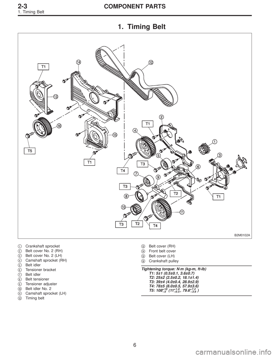
�1Crankshaft sprocket
�
2Belt cover No. 2 (RH)
�
3Belt cover No. 2 (LH)
�
4Camshaft sprocket (RH)
�
5Belt idler
�
6Tensioner bracket
�
7Belt idler
�
8Belt tensioner
�
9Tensioner adjuster
�
10Belt idler No. 2
�
11Camshaft sprocket (LH)
�
12Timing belt�
13Belt cover (RH)
�
14Front belt cover
�
15Belt cover (LH)
�
16Crankshaft pulley
Tightening torque: N⋅m (kg-m, ft-lb)
T1: 5±1 (0.5±0.1, 3.6±0.7)
T2: 25±2 (2.5±0.2, 18.1±1.4)
T3: 39±4 (4.0±0.4, 28.9±2.9)
T4: 78±5 (8.0±0.5, 57.9±3.6)
T5: 108
+10
�5(11+1.0
�0.5, 79.6+7.2
�3.6)
6
2-3COMPONENT PARTS
1. Timing Belt
Page 26 of 2248
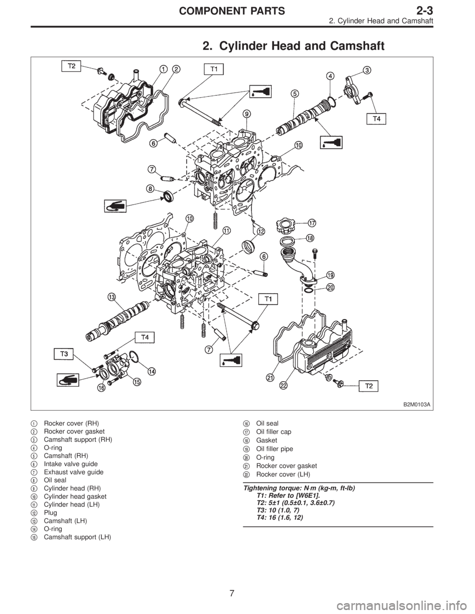
2. Cylinder Head and Camshaft
B2M0103A
�1Rocker cover (RH)
�
2Rocker cover gasket
�
3Camshaft support (RH)
�
4O-ring
�
5Camshaft (RH)
�
6Intake valve guide
�
7Exhaust valve guide
�
8Oil seal
�
9Cylinder head (RH)
�
10Cylinder head gasket
�
11Cylinder head (LH)
�
12Plug
�
13Camshaft (LH)
�
14O-ring
�
15Camshaft support (LH)�
16Oil seal
�
17Oil filler cap
�
18Gasket
�
19Oil filler pipe
�
20O-ring
�
21Rocker cover gasket
�
22Rocker cover (LH)
Tightening torque: N⋅m (kg-m, ft-lb)
T1: Refer to [W6E1].
T2: 5±1 (0.5±0.1, 3.6±0.7)
T3: 10 (1.0, 7)
T4: 16 (1.6, 12)
7
2-3COMPONENT PARTS
2. Cylinder Head and Camshaft
Page 28 of 2248
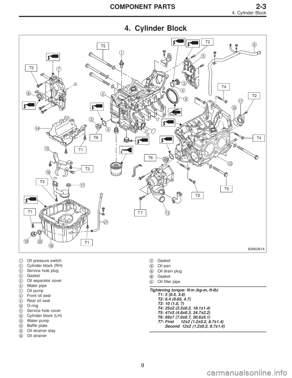
4. Cylinder Block
B2M0381A
�1Oil pressure switch
�
2Cylinder block (RH)
�
3Service hole plug
�
4Gasket
�
5Oil separator cover
�
6Water pipe
�
7Oil pump
�
8Front oil seal
�
9Rear oil seal
�
10O-ring
�
11Service hole cover
�
12Cylinder block (LH)
�
13Water pump
�
14Baffle plate
�
15Oil strainer stay
�
16Oil strainer�
17Gasket
�
18Oil pan
�
19Oil drain plug
�
20Gasket
�
21Oil filler pipe
Tightening torque: N⋅m (kg-m, ft-lb)
T1: 5 (0.5, 3.6)
T2: 6.4 (0.65, 4.7)
T3: 10 (1.0, 7)
T4: 25±2 (2.5±0.2, 18.1±1.4)
T5: 47±3 (4.8±0.3, 34.7±2.2)
T6: 69±7 (7.0±0.7, 50.6±5.1)
T7: First 12±2 (1.2±0.2, 8.7±1.4)
Second 12±2 (1.2±0.2, 8.7±1.4)
9
2-3COMPONENT PARTS
4. Cylinder Block
Page 30 of 2248
 Before disassembling engine, place it on ST3.
ST1 498457000 ENGINE STAND ADAPTER RH
ST2 498457100 ENGINE STAND ADAPTER LH
ST3 499817000 ENGINE STAND
2) All parts shou")
G2M0106
1. General Precautions
1) Before disassembling engine, place it on ST3.
ST1 498457000 ENGINE STAND ADAPTER RH
ST2 498457100 ENGINE STAND ADAPTER LH
ST3 499817000 ENGINE STAND
2) All parts should be thoroughly cleaned, paying special
attention to the engine oil passages, pistons and bearings.
3) Rotating parts and sliding parts such as piston, bearing
and gear should be coated with oil prior to assembly.
4) Be careful not to let oil, grease or coolant contact the
timing belt, clutch disc and flywheel.
5) All removed parts, if to be reused, should be reinstalled
in the original positions and directions.
6) Gaskets and lock washers must be replaced with new
ones. Liquid gasket should be used where specified to
prevent leakage.
7) Bolts, nuts and washers should be replaced with new
ones as required.
8) Even if necessary inspections have been made in
advance, proceed with assembly work while making
rechecks.
2. Hydraulic Lash Adjuster
A: INSPECTION
1) Disconnect blow-by hose from rocker cover.
2) Remove spark plug cap.
B2M0413A
3) Remove left and right rocker covers.
CAUTION:
Before removing left rocker cover, disconnect battery
cables and generator cable.
11
2-3SERVICE PROCEDURE
1. General Precautions - 2. Hydraulic Lash Adjuster
Page 31 of 2248
 Before disassembling engine, place it on ST3.
ST1 498457000 ENGINE STAND ADAPTER RH
ST2 498457100 ENGINE STAND ADAPTER LH
ST3 499817000 ENGINE STAND
2) All parts shou")
G2M0106
1. General Precautions
1) Before disassembling engine, place it on ST3.
ST1 498457000 ENGINE STAND ADAPTER RH
ST2 498457100 ENGINE STAND ADAPTER LH
ST3 499817000 ENGINE STAND
2) All parts should be thoroughly cleaned, paying special
attention to the engine oil passages, pistons and bearings.
3) Rotating parts and sliding parts such as piston, bearing
and gear should be coated with oil prior to assembly.
4) Be careful not to let oil, grease or coolant contact the
timing belt, clutch disc and flywheel.
5) All removed parts, if to be reused, should be reinstalled
in the original positions and directions.
6) Gaskets and lock washers must be replaced with new
ones. Liquid gasket should be used where specified to
prevent leakage.
7) Bolts, nuts and washers should be replaced with new
ones as required.
8) Even if necessary inspections have been made in
advance, proceed with assembly work while making
rechecks.
2. Hydraulic Lash Adjuster
A: INSPECTION
1) Disconnect blow-by hose from rocker cover.
2) Remove spark plug cap.
B2M0413A
3) Remove left and right rocker covers.
CAUTION:
Before removing left rocker cover, disconnect battery
cables and generator cable.
11
2-3SERVICE PROCEDURE
1. General Precautions - 2. Hydraulic Lash Adjuster
Page 34 of 2248
 Fill rocker arm’s oil reservoir with engine oil and install
lash adjuster.
CAUTION:
�Do not rotate lash adjuster during installation.
�Be careful not to scratch the oil seal.
B2M0414
CAUTION:
Whe")
6) Fill rocker arm’s oil reservoir with engine oil and install
lash adjuster.
CAUTION:
�Do not rotate lash adjuster during installation.
�Be careful not to scratch the oil seal.
B2M0414
CAUTION:
When removing valve rocker assembly, keep the
assembly soaked in engine oil, or position it with air
bleeding orifice on rocker arm facing upward as
shown. This prevents oil leakage from and air entering
into the hydraulic lash adjuster. Failure to do so may
cause air to enter the hydraulic lash adjuster, causing
loss in performance.
B2M0382B
7) Temporarily and equally tighten bolts�1through�4.Do
not allow knock pin to catch valve rocker assembly.
8) Tighten bolts�
5through�8to specified torque.
9) Tighten bolts�
1through�4to specified torque.
Tightening torque:
12±1 N⋅m (1.2±0.1 kg-m, 8.7±0.7 ft-lb)
10) Install rocker covers.
Tightening torque:
5±1 N⋅m (0.5±0.1 kg-m, 3.6±0.7 ft-lb)
11) Connect harness connectors, hoses, etc. to their posi-
tions.
14
2-3SERVICE PROCEDURE
2. Hydraulic Lash Adjuster
Page 35 of 2248
3. Timing Belt
A: REMOVAL
1. CRANKSHAFT PULLEY AND BELT COVER
G2M0107
G2M0108
1) Remove V-belt and A/C belt tensioner.
2) Remove pulley bolt. To lock crankshaft use ST.
ST 499977000 CRANKSHAFT PULLEY WRENCH
3) Remove crankshaft pulley.
4) Remove left side belt cover.
5) Remove right side belt cover.
6) Remove front belt cover.
15
2-3SERVICE PROCEDURE
3. Timing Belt
 Remove generator from bracket.
(1) Disconnect connector and terminal from generator.
G2M0089
(2) Remove V-belt cover.
(3) Loosen lock bolt and slider b")
 Remove V-belt and A/C belt tensioner.
2) Remove pulley bolt. To lock crankshaft use ST.
ST 499977000 CRANKSHAFT PULLEY")