Page 1180 of 2248
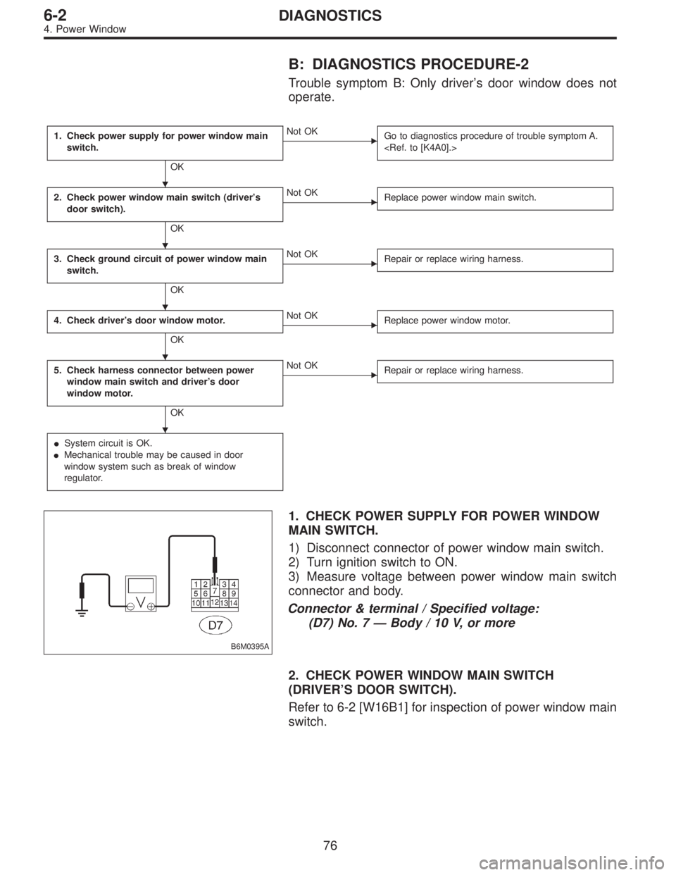
B: DIAGNOSTICS PROCEDURE-2
Trouble symptom B: Only driver’s door window does not
operate.
1. Check power supply for power window main
switch.
OK
�Not OK
Go to diagnostics procedure of trouble symptom A.
2. Check power window main switch (driver’s
door switch).
OK
�Not OK
Replace power window main switch.
3. Check ground circuit of power window main
switch.
OK
�Not OK
Repair or replace wiring harness.
4. Check driver’s door window motor.
OK
�Not OK
Replace power window motor.
5. Check harness connector between power
window main switch and driver’s door
window motor.
OK
�Not OK
Repair or replace wiring harness.
�System circuit is OK.
�Mechanical trouble may be caused in door
window system such as break of window
regulator.
B6M0395A
1. CHECK POWER SUPPLY FOR POWER WINDOW
MAIN SWITCH.
1) Disconnect connector of power window main switch.
2) Turn ignition switch to ON.
3) Measure voltage between power window main switch
connector and body.
Connector & terminal / Specified voltage:
(D7) No. 7—Body / 10 V, or more
2. CHECK POWER WINDOW MAIN SWITCH
(DRIVER’S DOOR SWITCH).
Refer to 6-2 [W16B1] for inspection of power window main
switch.
�
�
�
�
�
76
6-2DIAGNOSTICS
4. Power Window
Page 1182 of 2248
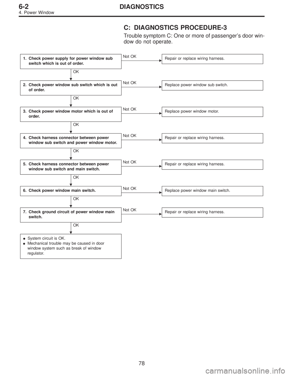
C: DIAGNOSTICS PROCEDURE-3
Trouble symptom C: One or more of passenger’s door win-
dow do not operate.
1. Check power supply for power window sub
switch which is out of order.
OK
�Not OK
Repair or replace wiring harness.
2. Check power window sub switch which is out
of order.
OK
�Not OK
Replace power window sub switch.
3. Check power window motor which is out of
order.
OK
�Not OK
Replace power window motor.
4. Check harness connector between power
window sub switch and power window motor.
OK
�Not OK
Repair or replace wiring harness.
5. Check harness connector between power
window sub switch and main switch.
OK
�Not OK
Repair or replace wiring harness.
6. Check power window main switch.
OK
�Not OK
Replace power window main switch.
7. Check ground circuit of power window main
switch.
OK
�Not OK
Repair or replace wiring harness.
�System circuit is OK.
�Mechanical trouble may be caused in door
window system such as break of window
regulator.
�
�
�
�
�
�
�
78
6-2DIAGNOSTICS
4. Power Window
Page 1185 of 2248
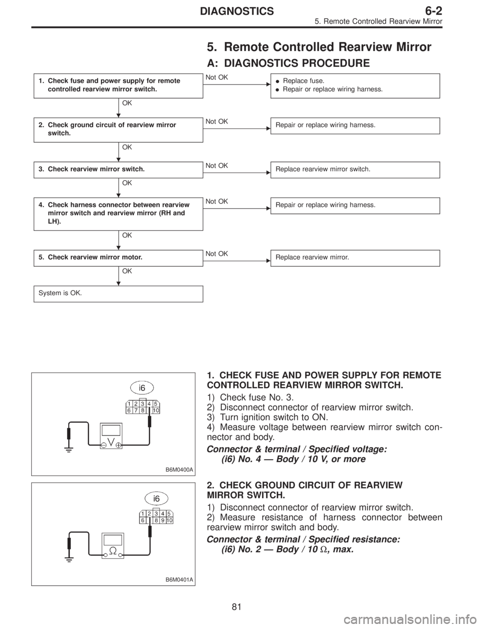
5. Remote Controlled Rearview Mirror
A: DIAGNOSTICS PROCEDURE
1. Check fuse and power supply for remote
controlled rearview mirror switch.
OK
�Not OK
�Replace fuse.
�Repair or replace wiring harness.
2. Check ground circuit of rearview mirror
switch.
OK
�Not OK
Repair or replace wiring harness.
3. Check rearview mirror switch.
OK
�Not OK
Replace rearview mirror switch.
4. Check harness connector between rearview
mirror switch and rearview mirror (RH and
LH).
OK
�Not OK
Repair or replace wiring harness.
5. Check rearview mirror motor.
OK
�Not OK
Replace rearview mirror.
System is OK.
B6M0400A
1. CHECK FUSE AND POWER SUPPLY FOR REMOTE
CONTROLLED REARVIEW MIRROR SWITCH.
1) Check fuse No. 3.
2) Disconnect connector of rearview mirror switch.
3) Turn ignition switch to ON.
4) Measure voltage between rearview mirror switch con-
nector and body.
Connector & terminal / Specified voltage:
(i6) No. 4—Body / 10 V, or more
B6M0401A
2. CHECK GROUND CIRCUIT OF REARVIEW
MIRROR SWITCH.
1) Disconnect connector of rearview mirror switch.
2) Measure resistance of harness connector between
rearview mirror switch and body.
Connector & terminal / Specified resistance:
(i6) No. 2—Body / 10Ω, max.
�
�
�
�
�
81
6-2DIAGNOSTICS
5. Remote Controlled Rearview Mirror
Page 1190 of 2248
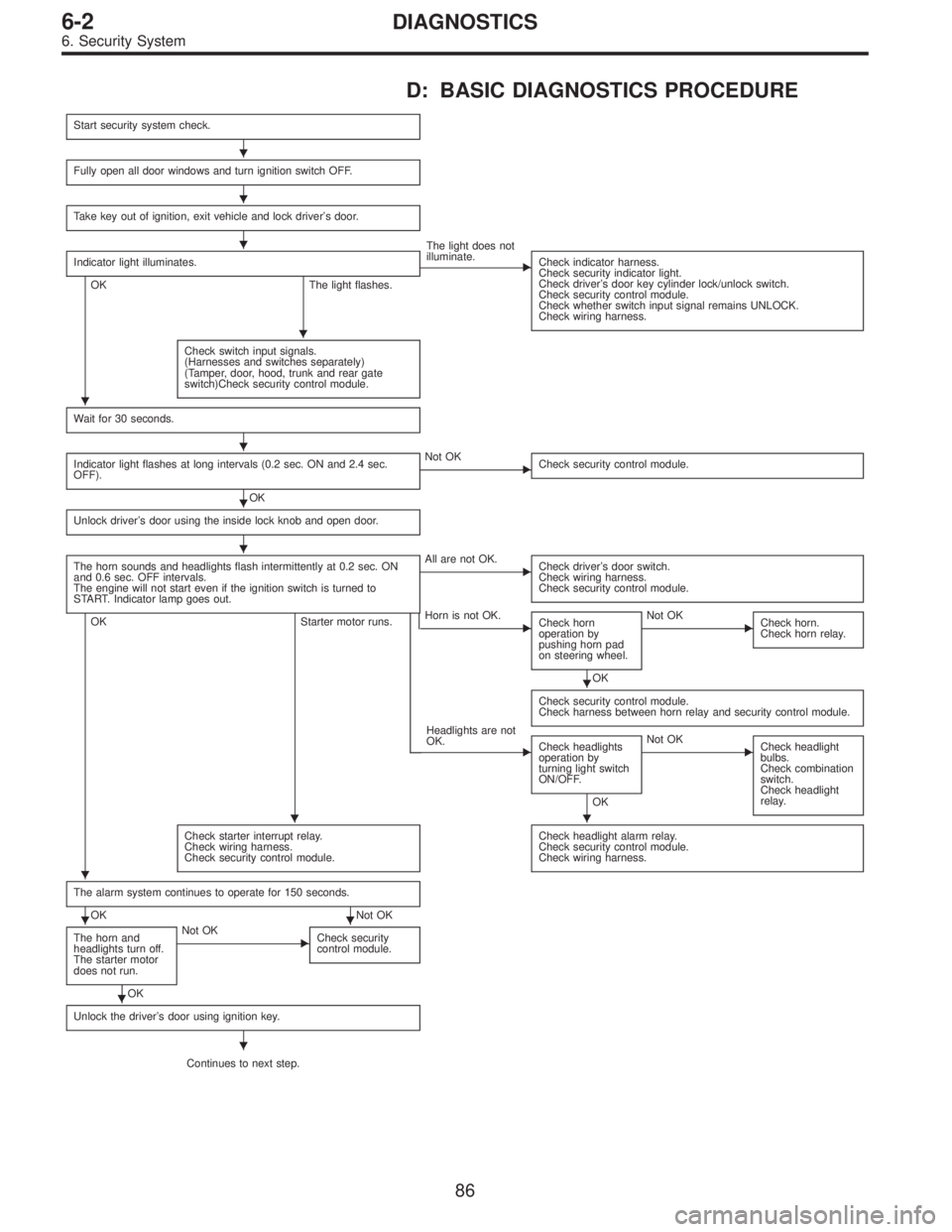
D: BASIC DIAGNOSTICS PROCEDURE
Start security system check.
Fully open all door windows and turn ignition switch OFF.
Take key out of ignition, exit vehicle and lock driver’s door.
Indicator light illuminates.
OK The light flashes.
� The light does not
illuminate.
Check indicator harness.
Check security indicator light.
Check driver’s door key cylinder lock/unlock switch.
Check security control module.
Check whether switch input signal remains UNLOCK.
Check wiring harness.
Check switch input signals.
(Harnesses and switches separately)
(Tamper, door, hood, trunk and rear gate
switch)Check security control module.
Wait for 30 seconds.
Indicator light flashes at long intervals (0.2 sec. ON and 2.4 sec.
OFF).
OK
� Not OK
Check security control module.
Unlock driver’s door using the inside lock knob and open door.
The horn sounds and headlights flash intermittently at 0.2 sec. ON
and 0.6 sec. OFF intervals.
The engine will not start even if the ignition switch is turned to
START. Indicator lamp goes out.
OK Starter motor runs.
� All are not OK.
Check driver’s door switch.
Check wiring harness.
Check security control module.
� Horn is not OK.
Check horn
operation by
pushing horn pad
on steering wheel.
OK
� Not OK
Check horn.
Check horn relay.
Check security control module.
Check harness between horn relay and security control module.
� Headlights are not
OK.
Check headlights
operation by
turning light switch
ON/OFF.
OK
� Not OK
Check headlight
bulbs.
Check combination
switch.
Check headlight
relay.
Check starter interrupt relay.
Check wiring harness.
Check security control module.Check headlight alarm relay.
Check security control module.
Check wiring harness.
The alarm system continues to operate for 150 seconds.
OK Not OK
The horn and
headlights turn off.
The starter motor
does not run.
OK
� Not OK
Check security
control module.
Unlock the driver’s door using ignition key.
Continues to next step.
�
�
�
�
�
�
�
�
�
��
�
��
�
�
86
6-2DIAGNOSTICS
6. Security System
Page 1191 of 2248
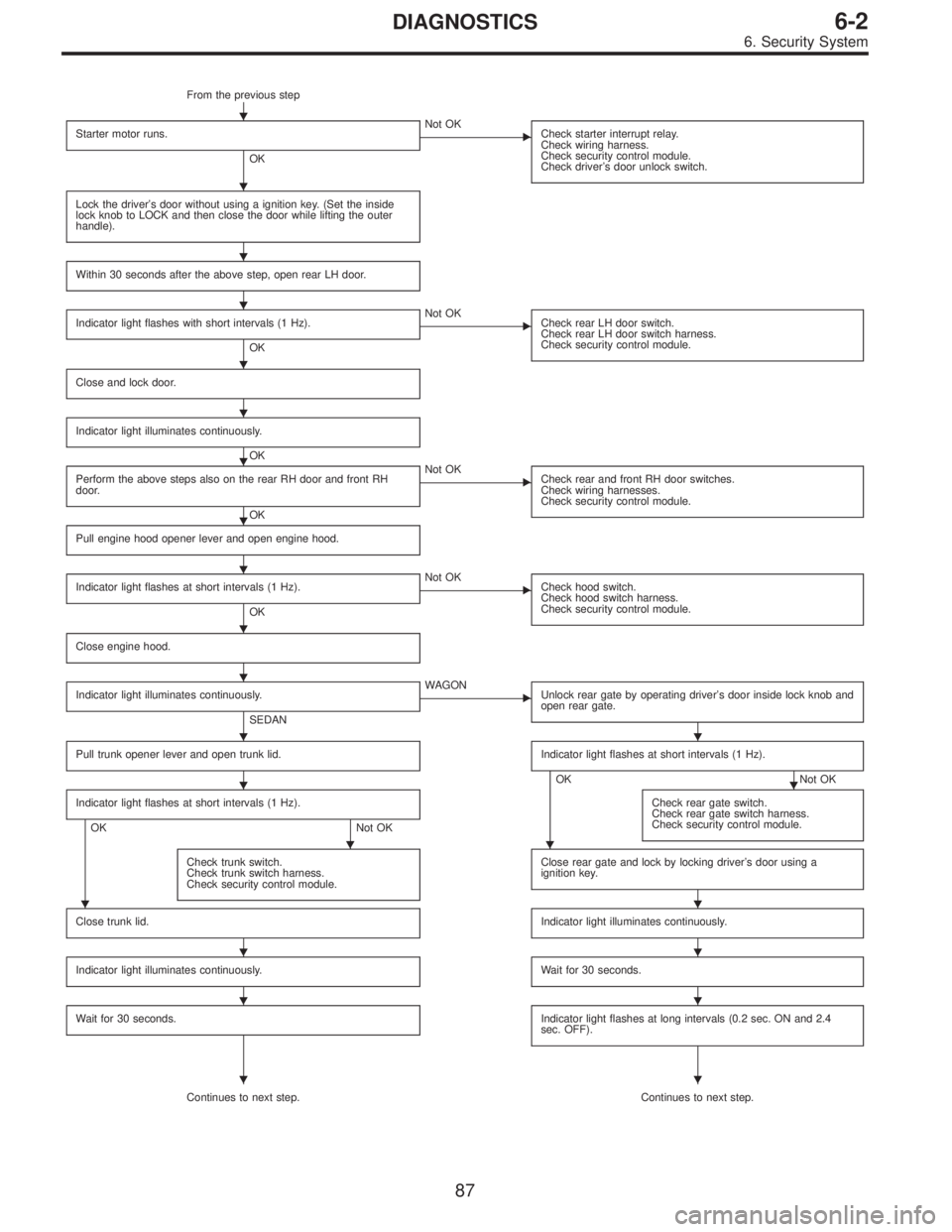
From the previous step
Starter motor runs.
OK
� Not OK
Check starter interrupt relay.
Check wiring harness.
Check security control module.
Check driver’s door unlock switch.
Lock the driver’s door without using a ignition key. (Set the inside
lock knob to LOCK and then close the door while lifting the outer
handle).
Within 30 seconds after the above step, open rear LH door.
Indicator light flashes with short intervals (1 Hz).
OK
� Not OK
Check rear LH door switch.
Check rear LH door switch harness.
Check security control module.
Close and lock door.
Indicator light illuminates continuously.
OK
Perform the above steps also on the rear RH door and front RH
door.
OK
� Not OK
Check rear and front RH door switches.
Check wiring harnesses.
Check security control module.
Pull engine hood opener lever and open engine hood.
Indicator light flashes at short intervals (1 Hz).
OK
� Not OK
Check hood switch.
Check hood switch harness.
Check security control module.
Close engine hood.
Indicator light illuminates continuously.
SEDAN
� WAGON
Unlock rear gate by operating driver’s door inside lock knob and
open rear gate.
Pull trunk opener lever and open trunk lid.Indicator light flashes at short intervals (1 Hz).
OK Not OK
Indicator light flashes at short intervals (1 Hz).
OK Not OKCheck rear gate switch.
Check rear gate switch harness.
Check security control module.
Check trunk switch.
Check trunk switch harness.
Check security control module.Close rear gate and lock by locking driver’s door using a
ignition key.
Close trunk lid.Indicator light illuminates continuously.
Indicator light illuminates continuously.Wait for 30 seconds.
Wait for 30 seconds.Indicator light flashes at long intervals (0.2 sec. ON and 2.4
sec. OFF).
Continues to next step. Continues to next step.
�
�
�
�
�
�
�
�
�
�
�
��
��
��
��
��
��
��
87
6-2DIAGNOSTICS
6. Security System
Page 1193 of 2248
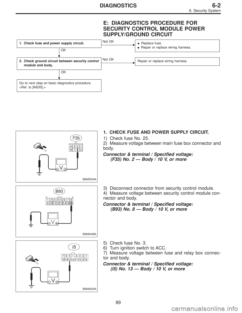
E: DIAGNOSTICS PROCEDURE FOR
SECURITY CONTROL MODULE POWER
SUPPLY/GROUND CIRCUIT
1. Check fuse and power supply circuit.
OK
�Not OK
�Replace fuse.
�Repair or replace wiring harness.
2. Check ground circuit between security control
module and body.
OK
�Not OK
Repair or replace wiring harness.
Go to next step on basic diagnostics procedure.
B6M0504A
1. CHECK FUSE AND POWER SUPPLY CIRCUIT.
1) Check fuse No. 25.
2) Measure voltage between main fuse box connector and
body.
Connector & terminal / Specified voltage:
(F35) No. 2—Body / 10 V, or more
B6M0448A
3) Disconnect connector from security control module.
4) Measure voltage between security control module con-
nector and body.
Connector & terminal / Specified voltage:
(B93) No. 8—Body / 10 V, or more
B6M0505A
5) Check fuse No. 3.
6) Turn ignition switch to ACC.
7) Measure voltage between fuse and relay box connec-
tor and body.
Connector & terminal / Specified voltage:
(i5) No. 13—Body / 10 V, or more
�
�
89
6-2DIAGNOSTICS
6. Security System
Page 1195 of 2248
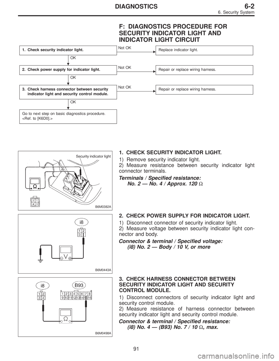
F: DIAGNOSTICS PROCEDURE FOR
SECURITY INDICATOR LIGHT AND
INDICATOR LIGHT CIRCUIT
1. Check security indicator light.
OK
�Not OK
Replace indicator light.
2. Check power supply for indicator light.
OK
�Not OK
Repair or replace wiring harness.
3. Check harness connector between security
indicator light and security control module.
OK
�Not OK
Repair or replace wiring harness.
Go to next step on basic diagnostics procedure.
B6M0382A
1. CHECK SECURITY INDICATOR LIGHT.
1) Remove security indicator light.
2) Measure resistance between security indicator light
connector terminals.
Terminals / Specified resistance:
No. 2—No. 4 / Approx. 120Ω
B6M0443A
2. CHECK POWER SUPPLY FOR INDICATOR LIGHT.
1) Disconnect connector of security indicator light.
2) Measure voltage between security indicator light con-
nector and body.
Connector & terminal / Specified voltage:
(i8) No. 2—Body / 10 V, or more
B6M0498A
3. CHECK HARNESS CONNECTOR BETWEEN
SECURITY INDICATOR LIGHT AND SECURITY
CONTROL MODULE.
1) Disconnect connectors of security indicator light and
security control module.
2) Measure resistance of harness connector between
security indicator light and security control module.
Connector & terminal / Specified resistance:
(i8) No. 4—(B93) No.7/10Ω, max.
�
�
�
91
6-2DIAGNOSTICS
6. Security System
Page 1196 of 2248
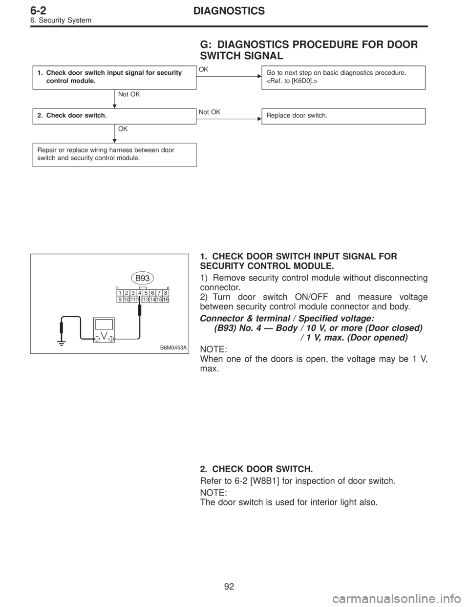
G: DIAGNOSTICS PROCEDURE FOR DOOR
SWITCH SIGNAL
1. Check door switch input signal for security
control module.
Not OK
�OK
Go to next step on basic diagnostics procedure.
2. Check door switch.
OK
�Not OK
Replace door switch.
Repair or replace wiring harness between door
switch and security control module.
B6M0453A
1. CHECK DOOR SWITCH INPUT SIGNAL FOR
SECURITY CONTROL MODULE.
1) Remove security control module without disconnecting
connector.
2) Turn door switch ON/OFF and measure voltage
between security control module connector and body.
Connector & terminal / Specified voltage:
(B93) No. 4—Body / 10 V, or more (Door closed)
/ 1 V, max. (Door opened)
NOTE:
When one of the doors is open, the voltage may be 1 V,
max.
2. CHECK DOOR SWITCH.
Refer to 6-2 [W8B1] for inspection of door switch.
NOTE:
The door switch is used for interior light also.
�
�
92
6-2DIAGNOSTICS
6. Security System