Page 19 of 2248
G2M0088
6. Engine Oil Pressure
A: MEASUREMENT
1) Remove generator from bracket.
(1) Disconnect connector and terminal from generator.
G2M0089
(2) Remove V-belt cover.
(3) Loosen lock bolt and slider bolt, and remove V-belt
for generator.
G2M0090
(4) Remove generator lock bolt.
(5) Remove bolt which install generator on bracket.
G2M0091
2) Disconnect connector from oil pressure switch.
3) Remove oil pressure switch from engine cylinder block.
7
2-2
6. Engine Oil Pressure
Page 20 of 2248
G2M0093
4) Connect oil pressure gauge hose to cylinder block.
5) Start the engine, and measure oil pressure.
Oil pressure:
98 kPa (1.0 kg/cm
2,14 psi) or more at 800 rpm
294 kPa (3.0 kg/cm2, 43 psi) or more at 5,000 rpm
CAUTION:
�If oil pressure is out of specification, check oil
pump, oil filter and lubrication line.
�If oil pressure warning light is turned ON and oil
pressure is in specification, replace oil pressure
switch.
NOTE:
The specified data is based on an engine oil temperature
of 80°C (176°F).
6) After measuring oil pressure, install oil pressure switch.
Tightening torque:
25±3 N⋅m (2.5±0.3 kg-m, 18.1±2.2 ft-lb)
7) Install generator and V-belt in the reverse order of
removal, and adjust the V-belt deflection.
8
2-2
6. Engine Oil Pressure
Page 21 of 2248
1. Engine
A: SPECIFICATIONS
EngineModel2200 cc
TypeHorizontally opposed, liquid cooled, 4-cylinder, 4-stroke
gasoline engine
Valve arrangement Belt driven, single over-head camshaft, 4-valve/cylinder
Bore x Stroke mm (in) 96.9 x 75.0 (3.815 x 2.953)
Displacement cm
3(cu in) 2,212 (135.0)
Compression ratio9.5
Compression pressure
(at 200 — 300 rpm)kPa (kg/cm
2, psi)1,079 — 1,275
(11.0 — 13.0, 156 — 185)
Number of piston rings Pressure ring: 2, Oil ring: 1
Intake valve timingOpening 1° BTDC
Closing 55° ABDC
Exhaust valve timingOpening 48° BBDC
Closing 12° ATDC
Idling speed
[At neutral position on MT, or
“P” or “N” position on AT] rpm700±100 (No load)
850±50 (A/C switch ON)
Firing order1,3,2,4
Ignition timing BTDC/rpm 14°±8°/700 (MT), 20°±8°/700 (AT)
2
2-3SPECIFICATIONS AND SERVICE DATA
1. Engine
Page 22 of 2248

Belt ten-
sionerSpacer O.D. 16 mm (0.63 in)
Tensioner bush I.D. 16.16 mm (0.6362 in)
Clearance between")
B: SERVICE DATA
Belt
tension
adjusterProtrusion of adjuster rod 15.4—16.4 mm (0.606—0.646 in)
Belt ten-
sionerSpacer O.D. 16 mm (0.63 in)
Tensioner bush I.D. 16.16 mm (0.6362 in)
Clearance between spacer and bushSTD 0.117—0.180 mm (0.0046—0.0071 in)
Limit 0.230 mm (0.0091 in)
Side clearance of spacerSTD 0.37—0.54 mm (0.0146—0.0213 in)
Limit 0.8 mm (0.031 in)
Valve
rocker armClearance between shaft and armSTD 0.020—0.054 mm (0.0008—0.0021 in)
Limit 0.10 mm (0.0039 in)
CamshaftBend limit 0.025 mm (0.0010 in)
Thrust clearanceSTD 0.030—0.260 mm (0.0012—0.0102 in)
Limit 0.35 mm (0.0138 in)
Cam lobe heightIntakeSTD 31.994—32.094 mm (1.2596—1.2635 in)
Limit 31.844 mm (1.2537 in)
ExhaustSTD 32.624—32.724 mm (1.2844—1.2883 in)
Limit 32.474 mm (1.2785 in)
Camshaft journal O.D. RHFront
LHRear 31.935—31.950 mm (1.2573—1.2579 in)
Center Center 37.435—37.450 mm (1.4738—1.4744 in)
Rear Front 37.935—37.950 mm (1.4935—1.4941 in)
Camshaft journal hole
I.D.RHFront
LHRear 32.005—32.025 mm (1.2600—1.2608 in)
Center Center 37.505—37.525 mm (1.4766—1.4774 in)
Rear Front 38.005—38.025 mm (1.4963—1.4970 in)
Oil clearanceSTD 0.055—0.090 mm (0.0022—0.0035 in)
Limit 0.10 mm (0.0039 in)
Cylinder
headSurface warpage limit 0.05 mm (0.0020 in)
Surface grinding limit 0.1 mm (0.004 in)
Standard height 98.3 mm (3.870 in)
Valve setRefacing angle 90°
Contacting widthIntakeSTD 0.7 mm (0.028 in)
Limit 1.4 mm (0.055 in)
ExhaustSTD 1.4 mm (0.055 in)
Limit 1.8 mm (0.071 in)
Valve
guideInner diameter 6.000—6.012 mm (0.2362—0.2367 in)
Protrusion above head 17.5—18.0 mm (0.689—0.709 in)
ValveHead edge thicknessIntakeSTD 1.0 mm (0.039 in)
Limit 0.8 mm (0.031 in)
ExhaustSTD 1.2 mm (0.047 in)
Limit 0.8 mm (0.031 in)
Stem diameterIntake 5.950—5.965 mm (0.2343—0.2348 in)
Exhaust 5.945—5.960 mm (0.2341—0.2346 in)
Stem oil clearanceSTDIntake 0.035—0.062 mm (0.0014—0.0024 in)
Exhaust 0.040—0.067 mm (0.0016—0.0026 in)
Limit—0.15 mm (0.0059 in)
Overall lengthIntake 101.0 mm (3.976 in)
Exhaust 101.2 mm (3.984 in)
STD: Standard I.D.: Inner Diameter O.D.: Outer Diameter
3
2-3SPECIFICATIONS AND SERVICE DATA
1. Engine
Page 25 of 2248
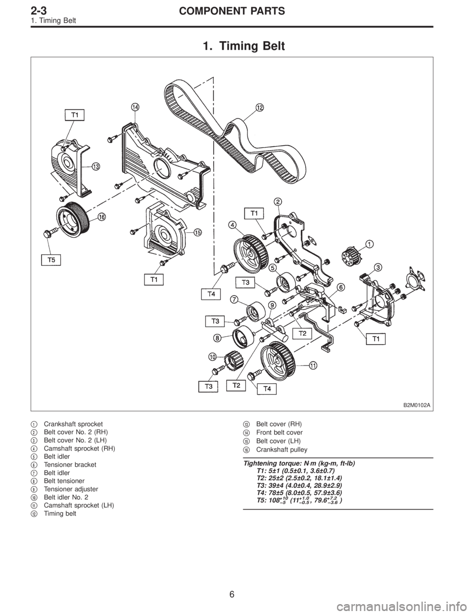
1. Timing Belt
B2M0102A
�1Crankshaft sprocket
�
2Belt cover No. 2 (RH)
�
3Belt cover No. 2 (LH)
�
4Camshaft sprocket (RH)
�
5Belt idler
�
6Tensioner bracket
�
7Belt idler
�
8Belt tensioner
�
9Tensioner adjuster
�
10Belt idler No. 2
�
11Camshaft sprocket (LH)
�
12Timing belt�
13Belt cover (RH)
�
14Front belt cover
�
15Belt cover (LH)
�
16Crankshaft pulley
Tightening torque: N⋅m (kg-m, ft-lb)
T1: 5±1 (0.5±0.1, 3.6±0.7)
T2: 25±2 (2.5±0.2, 18.1±1.4)
T3: 39±4 (4.0±0.4, 28.9±2.9)
T4: 78±5 (8.0±0.5, 57.9±3.6)
T5: 108
+10
�5(11+1.0
�0.5, 79.6+7.2
�3.6)
6
2-3COMPONENT PARTS
1. Timing Belt
Page 30 of 2248
 Before disassembling engine, place it on ST3.
ST1 498457000 ENGINE STAND ADAPTER RH
ST2 498457100 ENGINE STAND ADAPTER LH
ST3 499817000 ENGINE STAND
2) All parts shou")
G2M0106
1. General Precautions
1) Before disassembling engine, place it on ST3.
ST1 498457000 ENGINE STAND ADAPTER RH
ST2 498457100 ENGINE STAND ADAPTER LH
ST3 499817000 ENGINE STAND
2) All parts should be thoroughly cleaned, paying special
attention to the engine oil passages, pistons and bearings.
3) Rotating parts and sliding parts such as piston, bearing
and gear should be coated with oil prior to assembly.
4) Be careful not to let oil, grease or coolant contact the
timing belt, clutch disc and flywheel.
5) All removed parts, if to be reused, should be reinstalled
in the original positions and directions.
6) Gaskets and lock washers must be replaced with new
ones. Liquid gasket should be used where specified to
prevent leakage.
7) Bolts, nuts and washers should be replaced with new
ones as required.
8) Even if necessary inspections have been made in
advance, proceed with assembly work while making
rechecks.
2. Hydraulic Lash Adjuster
A: INSPECTION
1) Disconnect blow-by hose from rocker cover.
2) Remove spark plug cap.
B2M0413A
3) Remove left and right rocker covers.
CAUTION:
Before removing left rocker cover, disconnect battery
cables and generator cable.
11
2-3SERVICE PROCEDURE
1. General Precautions - 2. Hydraulic Lash Adjuster
Page 31 of 2248
 Before disassembling engine, place it on ST3.
ST1 498457000 ENGINE STAND ADAPTER RH
ST2 498457100 ENGINE STAND ADAPTER LH
ST3 499817000 ENGINE STAND
2) All parts shou")
G2M0106
1. General Precautions
1) Before disassembling engine, place it on ST3.
ST1 498457000 ENGINE STAND ADAPTER RH
ST2 498457100 ENGINE STAND ADAPTER LH
ST3 499817000 ENGINE STAND
2) All parts should be thoroughly cleaned, paying special
attention to the engine oil passages, pistons and bearings.
3) Rotating parts and sliding parts such as piston, bearing
and gear should be coated with oil prior to assembly.
4) Be careful not to let oil, grease or coolant contact the
timing belt, clutch disc and flywheel.
5) All removed parts, if to be reused, should be reinstalled
in the original positions and directions.
6) Gaskets and lock washers must be replaced with new
ones. Liquid gasket should be used where specified to
prevent leakage.
7) Bolts, nuts and washers should be replaced with new
ones as required.
8) Even if necessary inspections have been made in
advance, proceed with assembly work while making
rechecks.
2. Hydraulic Lash Adjuster
A: INSPECTION
1) Disconnect blow-by hose from rocker cover.
2) Remove spark plug cap.
B2M0413A
3) Remove left and right rocker covers.
CAUTION:
Before removing left rocker cover, disconnect battery
cables and generator cable.
11
2-3SERVICE PROCEDURE
1. General Precautions - 2. Hydraulic Lash Adjuster
Page 35 of 2248
3. Timing Belt
A: REMOVAL
1. CRANKSHAFT PULLEY AND BELT COVER
G2M0107
G2M0108
1) Remove V-belt and A/C belt tensioner.
2) Remove pulley bolt. To lock crankshaft use ST.
ST 499977000 CRANKSHAFT PULLEY WRENCH
3) Remove crankshaft pulley.
4) Remove left side belt cover.
5) Remove right side belt cover.
6) Remove front belt cover.
15
2-3SERVICE PROCEDURE
3. Timing Belt
 Remove generator from bracket.
(1) Disconnect connector and terminal from generator.
G2M0089
(2) Remove V-belt cover.
(3) Loosen lock bolt and slider b")
 Connect oil pressure gauge hose to cylinder block.
5) Start the engine, and measure oil pressure.
Oil pressure:
98 kPa (1.0 kg/cm
2,14 psi) or more at 800 rpm
294 kPa (3.0 kg/cm2, 43 psi) o")

 Remove V-belt and A/C belt tensioner.
2) Remove pulley bolt. To lock crankshaft use ST.
ST 499977000 CRANKSHAFT PULLEY")