Page 19 of 2248
G2M0088
6. Engine Oil Pressure
A: MEASUREMENT
1) Remove generator from bracket.
(1) Disconnect connector and terminal from generator.
G2M0089
(2) Remove V-belt cover.
(3) Loosen lock bolt and slider bolt, and remove V-belt
for generator.
G2M0090
(4) Remove generator lock bolt.
(5) Remove bolt which install generator on bracket.
G2M0091
2) Disconnect connector from oil pressure switch.
3) Remove oil pressure switch from engine cylinder block.
7
2-2
6. Engine Oil Pressure
Page 20 of 2248
G2M0093
4) Connect oil pressure gauge hose to cylinder block.
5) Start the engine, and measure oil pressure.
Oil pressure:
98 kPa (1.0 kg/cm
2,14 psi) or more at 800 rpm
294 kPa (3.0 kg/cm2, 43 psi) or more at 5,000 rpm
CAUTION:
�If oil pressure is out of specification, check oil
pump, oil filter and lubrication line.
�If oil pressure warning light is turned ON and oil
pressure is in specification, replace oil pressure
switch.
NOTE:
The specified data is based on an engine oil temperature
of 80°C (176°F).
6) After measuring oil pressure, install oil pressure switch.
Tightening torque:
25±3 N⋅m (2.5±0.3 kg-m, 18.1±2.2 ft-lb)
7) Install generator and V-belt in the reverse order of
removal, and adjust the V-belt deflection.
8
2-2
6. Engine Oil Pressure
Page 23 of 2248

Squareness 2.5°, 1.9 mm (0.075 in)
Tension/spring height174.6—200.1 N
(17.8—20.4 kg, 39.2—45.0 lb)/36.0 mm (1.417 in)
405.0—458.0 N
(41.3—46.7 k")
Valve springFree length 44.05 mm (1.7342 in)
Squareness 2.5°, 1.9 mm (0.075 in)
Tension/spring height174.6—200.1 N
(17.8—20.4 kg, 39.2—45.0 lb)/36.0 mm (1.417 in)
405.0—458.0 N
(41.3—46.7 kg, 91.1—103.0 lb)/28.2 mm (1.110 in)
Cylinder
blockSurface warpage limit (mating with cylinder head) 0.05 mm (0.0020 in)
Surface grinding limit 0.1 mm (0.004 in)
Cylinder bore STDA 96.905—96.915 mm (3.8151—3.8155 in)
B 96.895—96.905 mm (3.8148—3.8151 in)
TaperSTD 0.015 mm (0.0006 in)
Limit 0.050 mm (0.0020 in)
Out-of-roundnessSTD 0.010 mm (0.0004 in)
Limit 0.050 mm (0.0020 in)
Piston clearanceSTD 0.010—0.030 mm (0.0004—0.0012 in)
Limit 0.050 mm (0.0020 in)
Enlarging (boring) limit 0.5 mm (0.020 in)
Piston Outer diameterSTDA 96.885—96.895 mm (3.8144—3.8148 in)
B 96.875—96.885 mm (3.8140—3.8144 in)
0.25 mm (0.0098 in)
OS97.115—97.145 mm (3.8234—3.8246 in)
0.50 mm (0.0197 in)
OS97.365—97.395 mm (3.8333—3.8344 in)
Piston pinStandard clearance between piston
pin and hole in pistonSTD 0.004—0.010 mm (0.0002—0.0004 in)
Limit 0.020 mm (0.0008 in)
Degree of fitPiston pin must be fitted into position with thumb at 20°C
(68°F).
Piston ringPiston ring gapTop ringSTD 0.20—0.35 mm (0.0079—0.0138 in)
Limit 1.0 mm (0.039 in)
Second
ringSTD 0.20—0.50 mm (0.0079—0.0197 in)
Limit 1.0 mm (0.039 in)
Oil ringSTD 0.20—0.70 mm (0.0079—0.0276 in)
Limit 1.5 mm (0.059 in)
Clearance between piston
ring and piston ring grooveTop ringSTD 0.040—0.080mm (0.0016—0.0031 in)
Limit 0.15 mm (0.0059 in)
Second
ringSTD 0.030—0.070 mm (0.0012—0.0028 in)
Limit 0.15 mm (0.0059 in)
Connecting
rodBend twist per 100 mm (3.94 in) in
lengthLimit 0.10 mm (0.0039 in)
Side clearanceSTD 0.070—0.330 mm (0.0028—0.0130 in)
Limit 0.4 mm (0.016 in)
Connecting
rod bearingOil clearanceSTD 0.015—0.045 mm (0.0006—0.0018 in)
Limit 0.05 mm (0.0020 in)
Thickness at center portionSTD 1.492—1.501 mm (0.0587—0.0591 in)
0.03 mm
(0.0012 in)
US1.510—1.513 mm (0.0594—0.0596 in)
0.05 mm
(0.0020 in)
US1.520—1.523 mm (0.0598—0.0600 in)
0.25 mm
(0.0098 in)
US1.620—1.623 mm (0.0638—0.0639 in)
Connecting
rod bushingClearance between piston pin and
bushingSTD 0—0.022 mm (0—0.0009 in)
Limit 0.030 mm (0.0012 in)
STD: Standard OS: Oversize US: Undersize
4
2-3SPECIFICATIONS AND SERVICE DATA
1. Engine
Page 28 of 2248
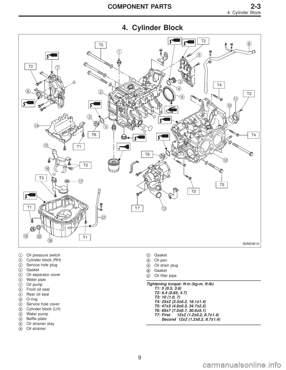
4. Cylinder Block
B2M0381A
�1Oil pressure switch
�
2Cylinder block (RH)
�
3Service hole plug
�
4Gasket
�
5Oil separator cover
�
6Water pipe
�
7Oil pump
�
8Front oil seal
�
9Rear oil seal
�
10O-ring
�
11Service hole cover
�
12Cylinder block (LH)
�
13Water pump
�
14Baffle plate
�
15Oil strainer stay
�
16Oil strainer�
17Gasket
�
18Oil pan
�
19Oil drain plug
�
20Gasket
�
21Oil filler pipe
Tightening torque: N⋅m (kg-m, ft-lb)
T1: 5 (0.5, 3.6)
T2: 6.4 (0.65, 4.7)
T3: 10 (1.0, 7)
T4: 25±2 (2.5±0.2, 18.1±1.4)
T5: 47±3 (4.8±0.3, 34.7±2.2)
T6: 69±7 (7.0±0.7, 50.6±5.1)
T7: First 12±2 (1.2±0.2, 8.7±1.4)
Second 12±2 (1.2±0.2, 8.7±1.4)
9
2-3COMPONENT PARTS
4. Cylinder Block
Page 30 of 2248
 Before disassembling engine, place it on ST3.
ST1 498457000 ENGINE STAND ADAPTER RH
ST2 498457100 ENGINE STAND ADAPTER LH
ST3 499817000 ENGINE STAND
2) All parts shou")
G2M0106
1. General Precautions
1) Before disassembling engine, place it on ST3.
ST1 498457000 ENGINE STAND ADAPTER RH
ST2 498457100 ENGINE STAND ADAPTER LH
ST3 499817000 ENGINE STAND
2) All parts should be thoroughly cleaned, paying special
attention to the engine oil passages, pistons and bearings.
3) Rotating parts and sliding parts such as piston, bearing
and gear should be coated with oil prior to assembly.
4) Be careful not to let oil, grease or coolant contact the
timing belt, clutch disc and flywheel.
5) All removed parts, if to be reused, should be reinstalled
in the original positions and directions.
6) Gaskets and lock washers must be replaced with new
ones. Liquid gasket should be used where specified to
prevent leakage.
7) Bolts, nuts and washers should be replaced with new
ones as required.
8) Even if necessary inspections have been made in
advance, proceed with assembly work while making
rechecks.
2. Hydraulic Lash Adjuster
A: INSPECTION
1) Disconnect blow-by hose from rocker cover.
2) Remove spark plug cap.
B2M0413A
3) Remove left and right rocker covers.
CAUTION:
Before removing left rocker cover, disconnect battery
cables and generator cable.
11
2-3SERVICE PROCEDURE
1. General Precautions - 2. Hydraulic Lash Adjuster
Page 31 of 2248
 Before disassembling engine, place it on ST3.
ST1 498457000 ENGINE STAND ADAPTER RH
ST2 498457100 ENGINE STAND ADAPTER LH
ST3 499817000 ENGINE STAND
2) All parts shou")
G2M0106
1. General Precautions
1) Before disassembling engine, place it on ST3.
ST1 498457000 ENGINE STAND ADAPTER RH
ST2 498457100 ENGINE STAND ADAPTER LH
ST3 499817000 ENGINE STAND
2) All parts should be thoroughly cleaned, paying special
attention to the engine oil passages, pistons and bearings.
3) Rotating parts and sliding parts such as piston, bearing
and gear should be coated with oil prior to assembly.
4) Be careful not to let oil, grease or coolant contact the
timing belt, clutch disc and flywheel.
5) All removed parts, if to be reused, should be reinstalled
in the original positions and directions.
6) Gaskets and lock washers must be replaced with new
ones. Liquid gasket should be used where specified to
prevent leakage.
7) Bolts, nuts and washers should be replaced with new
ones as required.
8) Even if necessary inspections have been made in
advance, proceed with assembly work while making
rechecks.
2. Hydraulic Lash Adjuster
A: INSPECTION
1) Disconnect blow-by hose from rocker cover.
2) Remove spark plug cap.
B2M0413A
3) Remove left and right rocker covers.
CAUTION:
Before removing left rocker cover, disconnect battery
cables and generator cable.
11
2-3SERVICE PROCEDURE
1. General Precautions - 2. Hydraulic Lash Adjuster
Page 33 of 2248
 Bleed air from hydraulic lash adjuster as described
below:
(1) While dipping hydraulic lash adjuster in engine oil,
as shown in Figure, push check ball in usinga2mm
(0.08 in) diameter round")
G2M0131
3) Bleed air from hydraulic lash adjuster as described
below:
(1) While dipping hydraulic lash adjuster in engine oil,
as shown in Figure, push check ball in usinga2mm
(0.08 in) diameter round bar.
(2) With check ball pushed in, manually move plunger
up and down at one second intervals until air bubbles
disappear.
(3) After air bubbles disappear, remove round bar and
quickly push plunger in to ensure it is locked. If plunger
does not lock properly, replace hydraulic lash adjuster.
CAUTION:
Leave hydraulic lash adjuster (after air is bled) in
engine oil until it is ready for installation.
G2M0200
4) Using ST;
(1) Insert lash adjuster into ST, and fill ST with engine
oil. Usinga2mm(0.08 in) diameter rod, push check
ball in.
ST 499597000 OIL SEAL GUIDE
(2) With check ball pushed in, push plunger at an inter-
val of one second.
(3) Move plunger up and down until air bubbles are no
longer emitted from lash adjuster.
NOTE:
Hold hydraulic lash adjusters vertically during air bleeding.
5) Remove the rod. Push plunger to ensure that air is
completely bled out.
CAUTION:
If plunger does not properly lock (when pushed),
replace lash adjuster with a new one.
13
2-3SERVICE PROCEDURE
2. Hydraulic Lash Adjuster
Page 35 of 2248
3. Timing Belt
A: REMOVAL
1. CRANKSHAFT PULLEY AND BELT COVER
G2M0107
G2M0108
1) Remove V-belt and A/C belt tensioner.
2) Remove pulley bolt. To lock crankshaft use ST.
ST 499977000 CRANKSHAFT PULLEY WRENCH
3) Remove crankshaft pulley.
4) Remove left side belt cover.
5) Remove right side belt cover.
6) Remove front belt cover.
15
2-3SERVICE PROCEDURE
3. Timing Belt
 Remove generator from bracket.
(1) Disconnect connector and terminal from generator.
G2M0089
(2) Remove V-belt cover.
(3) Loosen lock bolt and slider b")
 Connect oil pressure gauge hose to cylinder block.
5) Start the engine, and measure oil pressure.
Oil pressure:
98 kPa (1.0 kg/cm
2,14 psi) or more at 800 rpm
294 kPa (3.0 kg/cm2, 43 psi) o")
 Remove V-belt and A/C belt tensioner.
2) Remove pulley bolt. To lock crankshaft use ST.
ST 499977000 CRANKSHAFT PULLEY")