Page 15 of 2248
 Before checking idle speed, check the following:
(1) Ensure that air cleaner element is free from
clogging, ignition timing is correct, spark plugs are in
good c")
3. Engine Idle Speed
A: MEASUREMENT
1) Before checking idle speed, check the following:
(1) Ensure that air cleaner element is free from
clogging, ignition timing is correct, spark plugs are in
good condition, and that hoses are connected properly.
(2) Ensure that malfunction indicator light (CHECK
ENGINE light) does not illuminate.
2) Warm-up the engine.
G2M0096
3) Connect Subaru Select Monitor or the OBD-II general
scan tool to data link connector.
CAUTION:
When connecting Subaru Select Monitor, turn ignition
switch to OFF.
4) Start the engine and measure engine speed.
NOTE:
Engine speed is indicated on Subaru Select Monitor by
selecting “MODE F04”.
G2M0097
NOTE:
�When using the OBD-II general scan tool, carefully read
its operation manual.
�When Subaru Select Monitor is not used, attach the
pickup sensor on tachometer (Secondary pickup type) to
#1 cylinder spark plug cord.
�This ignition system provides simultaneous ignition for
#1 and #2 plugs. It must be noted that some tachometers
may register twice that of actual engine speed.
3
2-2
3. Engine Idle Speed
Page 174 of 2248
 Disconnect connector from throttle position sensor.
2) Remove throttle position sensor holding screws, and
remove it.
3) Installation")
B2M0162
9. Throttle Position Sensor
A: REMOVAL AND INSTALLATION
1) Disconnect connector from throttle position sensor.
2) Remove throttle position sensor holding screws, and
remove it.
3) Installation is in the reverse order of removal.
Tightening torque:
2.2±0.2 N⋅m (0.22±0.02 kg-m, 1.6±0.1 ft-lb)
CAUTION:
When installing throttle position sensor, adjust to the
specified data.
B2M0163
B: ADJUSTMENT
1) Turn ignition switch to OFF.
2) Loosen throttle position sensor holding screws.
G2M0415
3) When using voltage meter;
(1) Take out ECM.
(2) Turn ignition switch to ON.
(3) Adjust throttle position sensor so that signal voltage
to ECM may be in specification.
Connector & Terminal / Specified voltage
(B84) No. 24 — (B84) No. 25 / 0.45 — 0.55 V
[Fully closed.]
(4) Tighten throttle position sensor holding screws.
G2M0096
4) When using Subaru Select Monitor;
(1) Connect Subaru Select Monitor to the data link con-
nector.
(2) Turn ignition switch to ON and SSM switch to ON.
(3) Select mode “F10”.
(4) Adjust throttle position sensor to specified data.
Condition / Specified data.
Throttle fully closed / 0.50 V
(5) Tighten throttle position sensor holding screws.
21
2-7SERVICE PROCEDURE
9. Throttle Position Sensor
Page 178 of 2248
 Slowly pour one can (16 oz) of cleaner into by-pass air
hole.
Cleaner:
�Part No. 1050002 GM Top Engine Cleaner
�Part No. X66-A AC Delco Carburetor Tune-up
Conditioner
5) Leave the engine ru")
B2M0358
4) Slowly pour one can (16 oz) of cleaner into by-pass air
hole.
Cleaner:
�Part No. 1050002 GM Top Engine Cleaner
�Part No. X66-A AC Delco Carburetor Tune-up
Conditioner
5) Leave the engine running for five minutes.
NOTE:
White smoke comes out of the muffler until the cleaner is
used up.
6) Stop the engine.
B2M0359
7) Release the throttle valve.
8) Connect by-pass hose to idle air control solenoid valve.
G2M0096
9) Check duty ratio of idle air control solenoid valve with
Subaru Select Monitor.
(1) Connect Subaru Select Monitor to the data link con-
nector.
(2) Start the engine and turn Subaru Select Monitor
switch to ON.
(3) Select mode“F12”.
(4) Make sure duty ratio on radiator fan and electric
load is OFF.
Specified data: 25—40%
B2M0361
13. Pressure Sources Switching
Solenoid Valve (AT model)
A: REMOVAL AND INSTALLATION
1) Disconnect connector from pressure sources switching
solenoid valve.
2) Disconnect hoses from pressure sources switching
solenoid valve.
24
2-7SERVICE PROCEDURE
12. Idle Air Control Solenoid Valve - 13. Pressure Sources Switching Solenoid Valve (AT model)
Page 179 of 2248
 Slowly pour one can (16 oz) of cleaner into by-pass air
hole.
Cleaner:
�Part No. 1050002 GM Top Engine Cleaner
�Part No. X66-A AC Delco Carburetor Tune-up
Conditioner
5) Leave the engine ru")
B2M0358
4) Slowly pour one can (16 oz) of cleaner into by-pass air
hole.
Cleaner:
�Part No. 1050002 GM Top Engine Cleaner
�Part No. X66-A AC Delco Carburetor Tune-up
Conditioner
5) Leave the engine running for five minutes.
NOTE:
White smoke comes out of the muffler until the cleaner is
used up.
6) Stop the engine.
B2M0359
7) Release the throttle valve.
8) Connect by-pass hose to idle air control solenoid valve.
G2M0096
9) Check duty ratio of idle air control solenoid valve with
Subaru Select Monitor.
(1) Connect Subaru Select Monitor to the data link con-
nector.
(2) Start the engine and turn Subaru Select Monitor
switch to ON.
(3) Select mode“F12”.
(4) Make sure duty ratio on radiator fan and electric
load is OFF.
Specified data: 25—40%
B2M0361
13. Pressure Sources Switching
Solenoid Valve (AT model)
A: REMOVAL AND INSTALLATION
1) Disconnect connector from pressure sources switching
solenoid valve.
2) Disconnect hoses from pressure sources switching
solenoid valve.
24
2-7SERVICE PROCEDURE
12. Idle Air Control Solenoid Valve - 13. Pressure Sources Switching Solenoid Valve (AT model)
Page 802 of 2248
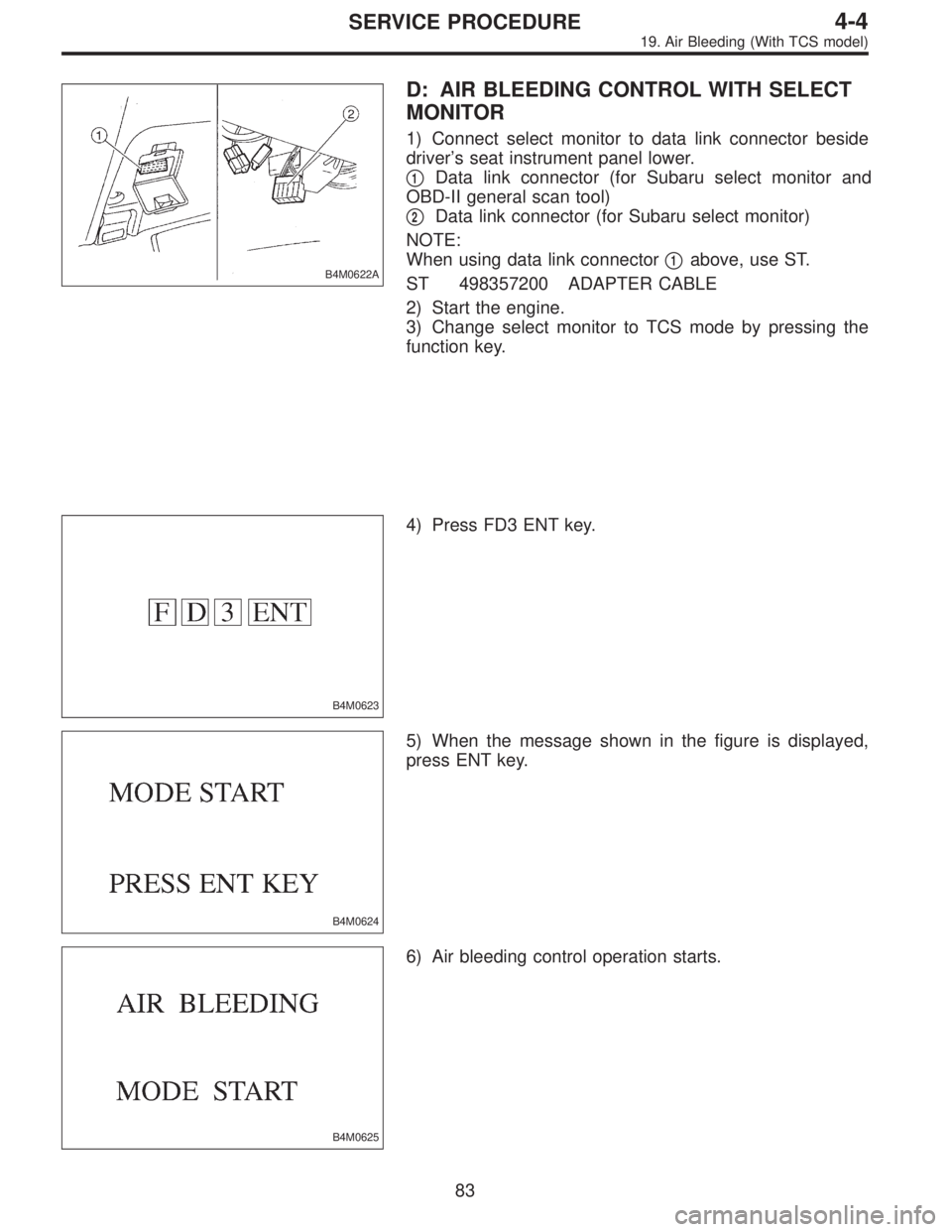
B4M0622A
D: AIR BLEEDING CONTROL WITH SELECT
MONITOR
1) Connect select monitor to data link connector beside
driver’s seat instrument panel lower.
�
1Data link connector (for Subaru select monitor and
OBD-II general scan tool)
�
2Data link connector (for Subaru select monitor)
NOTE:
When using data link connector�
1above, use ST.
ST 498357200 ADAPTER CABLE
2) Start the engine.
3) Change select monitor to TCS mode by pressing the
function key.
B4M0623
4) Press FD3 ENT key.
B4M0624
5) When the message shown in the figure is displayed,
press ENT key.
B4M0625
6) Air bleeding control operation starts.
83
4-4SERVICE PROCEDURE
19. Air Bleeding (With TCS model)
Page 808 of 2248
 Under the ABS sequence control, after the hydraulic
unit solenoid valve is driven, the operation of the hydraulic
unit can be checked by means of the brake tester or pres-
s")
D: ABS SEQUENCE CONTROL
1) Under the ABS sequence control, after the hydraulic
unit solenoid valve is driven, the operation of the hydraulic
unit can be checked by means of the brake tester or pres-
sure gauge.
2) ABS sequence control can be started by diagnosis con-
nector or select monitor.
B4M0082C
1. OPERATIONAL GUIDELINES OF THE ABS
SEQUENCE CONTROL WITH DIAGNOSIS
CONNECTOR
1) Connect diagnosis terminals to terminal No. 4 of the
diagnosis connector beside driver’s seat heater unit.
2) Ignition switch is turned to ON.
3) Make sure only the start code (code 11) is shown in
normal condition.
NOTE:
When trouble codes are stored in memory, repair the faulty
parts.
4) Set the speed of all wheels at 10 km/h (6 MPH) or less.
5) Turn ignition switch OFF.
6) Within 0.5 seconds after the ABS and TCS warning
lights go out, depress the brake pedal and hold it immedi-
ately after engine starts.
NOTE:
�When the ignition switch is set to on, the brake pedal
must not be depressed.
�Engine must operate.
�If brake pedal is not depressed within 0.5 seconds after
ABS and TCS warning lights go out, the trouble code mode
comes on.
7) After completion of ABS sequence control, turn ignition
switch OFF.
2. OPERATIONAL GUIDELINES OF THE ABS
SEQUENCE CONTROL WITH SELECT MONITOR
1) Connect select monitor to data link connector beside
driver’s seat heater unit.
2) Engine starts.
3) Put select monitor to TCS mode.
4) put select monitor to FBI mode. Make sure code 11 is
indicated.
NOTE:
When trouble codes are stored in memory, repair the faulty
parts.
89
4-4SERVICE PROCEDURE
20. Hydraulic Unit for ABS/TCS System
Page 815 of 2248
2. OPERATIONAL GUIDELINES OF THE TCS
SEQUENCE CONTROL WITH SELECT MONITOR
1) Connect select monitor to data link connector beside
driver’s seat heater unit.
2) Engine starts.
3) Put select monitor to TCS mode.
4) Put select monitor to FBI mode. Make sure code 11 is
indicated.
NOTE:
When trouble codes are stored in memory, repair the faulty
parts.
B4M0639
5) Press FD2 ENT key.
B4M0624
6) When the message shown in the figure is displayed,
press ENT key.
7) Checked portions will be displayed on select monitor.
B4M0627
8) When TCS sequence control cannot be started (by sys-
tem malfunction, etc.), the message shown in the figure will
be displayed.
NOTE:
Read the trouble codes. Repair faulty parts.
96
4-4SERVICE PROCEDURE
20. Hydraulic Unit for ABS/TCS System
Page 1208 of 2248
 system detects and
indicates a fault in various inputs and outputs of the com-
plex electronic control. CHECK ENGINE malfunction indi-")
1. General
1. GENERAL DESCRIPTION
�The on-board diagnostics (OBD) system detects and
indicates a fault in various inputs and outputs of the com-
plex electronic control. CHECK ENGINE malfunction indi-
cator lamp (MIL) in the combination meter indicates occur-
rence of a fault or trouble.
�Further, against such a failure or sensors as may disable
the drive, the fail-safe function is provided to ensure the
minimal driveability.
�The OBD system incorporated with the vehicles within
this engine family complies with Section 1968.1, California
Code of Regulations (OBD-II regulation). The OBD system
monitors the components and the system malfunction
listed in Engine Section which affects on emissions.
�When the system decides that a malfunction occurs, MIL
illuminates. At the same time of the MIL illumination or
blinking, a diagnostic trouble code (DTC) and a freeze
frame engine conditions are stored into on-board com-
puter.
�The OBD system stores freeze frame engine condition
data (engine load, engine coolant temperature, fuel trim,
engine speed and vehicle speed, etc.) into on-board com-
puter when it detects a malfunction first.
�If the OBD system detects the various malfunctions
including the fault of fuel trim or misfire, the OBD system
first stores freeze frame engine conditions about the fuel
trim or misfire.
�When the malfunction does not occur again for three
trips, MIL is turned off, but DTC remains at on-board com-
puter.
�The OBD-II system is capable of communication with a
general scan tool (OBD-II general scan tool) formed by ISO
9141 CARB.
�The OBD-II diagnostics procedure is different from the
usual diagnostics procedure. When troubleshooting OBD-II
vehicles, connect Subaru select monitor or the OBD-II gen-
eral scan tool to the vehicle.
A: ENGINE
1. ENGINE AND EMISSION CONTROL SYSTEM
�The Multipoint Fuel Injection (MFI) system is a system
that supplies the optimum air-fuel mixture to the engine for
all the various operating conditions through the use of the
latest electronic technology.
With this system fuel, which is pressurized at a constant
pressure, is injected into the intake air passage of the cyl-
inder head. The injection quantity of fuel is controlled by an
intermittent injection system where the electro-magnetic
injection valve (fuel injector) opens only for a short period
of time, depending on the quantity of air required for one
cycle of operation. In actual operation, the injection quan-
2
2-7ON-BOARD DIAGNOSTICS II SYSTEM
1. General
![SUBARU LEGACY 1995 Service Repair Manual 2. OPERATIONAL GUIDELINES OF THE TCS
SEQUENCE CONTROL WITH SELECT MONITOR
1) Connect select monitor to data link connector beside
driver’s seat heater unit. <Ref. to [W19D0] step 1).>
2) Engine star](/manual-img/17/57432/w960_57432-814.png "SUBARU LEGACY 1995 Service Repair Manual 2. OPERATIONAL GUIDELINES OF THE TCS
SEQUENCE CONTROL WITH SELECT MONITOR
1) Connect select monitor to data link connector beside
driver’s seat heater unit. <Ref. to [W19D0] step 1).>
2) Engine star")