Page 1211 of 2248

�
2Ignition coil
�
3Ignitor
�
4Crankshaft position sensor
�
5Camshaft position sensor
�
6Throttle position sensor
�
7Fuel injectors
�
8Pressure regulator
�
9Engine coolan")
�1Engine control module (ECM)
�
2Ignition coil
�
3Ignitor
�
4Crankshaft position sensor
�
5Camshaft position sensor
�
6Throttle position sensor
�
7Fuel injectors
�
8Pressure regulator
�
9Engine coolant temperature sensor
�
10Mass air flow sensor
�
11Idle air control solenoid valve
�
12Purge control solenoid valve
�
13Fuel pump
�
14PCV valve
�
15Air cleaner
�
16Canister
�
17Main relay
�
18Fuel pump relay
�
19Fuel filter
�
20Front catalytic converter
�
21Rear catalytic converter
�
22EGR valve�
23EGR control solenoid valve
�
24Radiator fan
�
25Radiator fan relay
�
26Pressure sources switching solenoid valve (AT vehicles only)
�
27Knock sensor
�
28Back-pressure transducer (AT vehicles only)
�
29Front oxygen sensor
�
30Rear oxygen sensor
�
31Pressure sensor (AT vehicles only)
�
32A/C compressor
�
33Inhibitor switch
�
34CHECK ENGINE malfunction indicator lamp (MIL)
�
35Tachometer
�
36A/C relay
�
37A/C control module
�
38Ignition switch
�
39Transmission control module (TCM) (AT vehicles only)
�
40ABS/TCS control module (TCS equipped models)
�
41Vehicle speed sensor
�
42Data link connector (Subaru select monitor)
�
43Data link connector (OBD-II general scan tool)
�
44Two way valve
5
2-7ON-BOARD DIAGNOSTICS II SYSTEM
1. General
Page 1214 of 2248
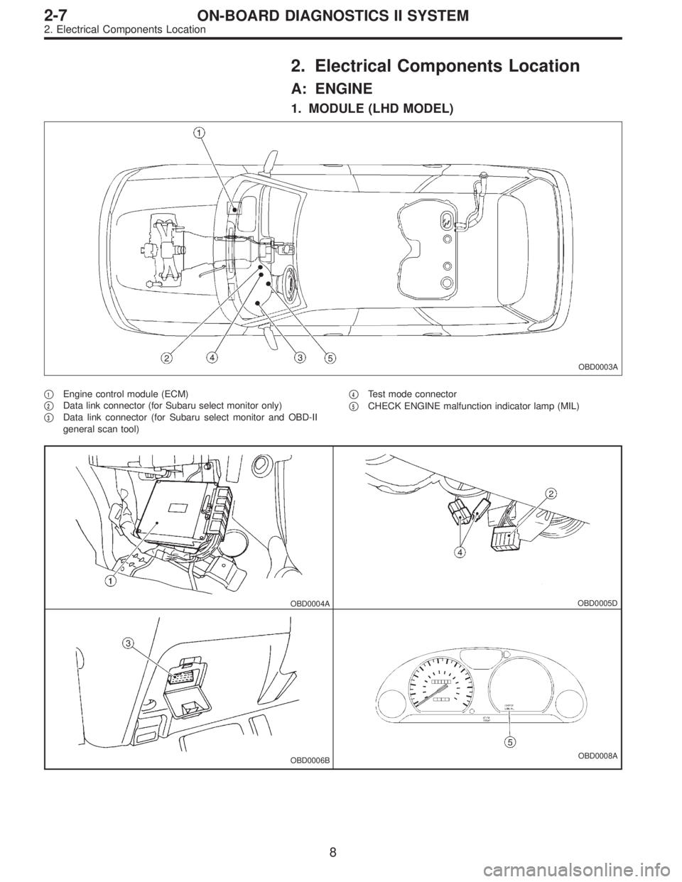
2. Electrical Components Location
A: ENGINE
1. MODULE (LHD MODEL)
OBD0003A
�1Engine control module (ECM)
�
2Data link connector (for Subaru select monitor only)
�
3Data link connector (for Subaru select monitor and OBD-II
general scan tool)�
4Test mode connector
�
5CHECK ENGINE malfunction indicator lamp (MIL)
OBD0004AOBD0005D
OBD0006BOBD0008A
8
2-7ON-BOARD DIAGNOSTICS II SYSTEM
2. Electrical Components Location
Page 1215 of 2248
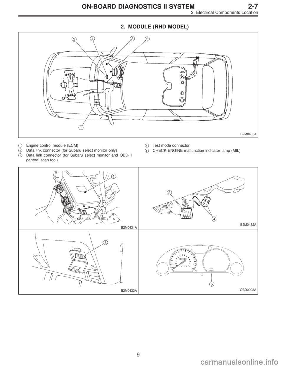
2. MODULE (RHD MODEL)
B2M0430A
�1Engine control module (ECM)
�
2Data link connector (for Subaru select monitor only)
�
3Data link connector (for Subaru select monitor and OBD-II
general scan tool)�
4Test mode connector
�
5CHECK ENGINE malfunction indicator lamp (MIL)
B2M0431AB2M0432A
B2M0433AOBD0008A
9
2-7ON-BOARD DIAGNOSTICS II SYSTEM
2. Electrical Components Location
Page 1234 of 2248
 Prepare a general scan tool (OBD-II general scan tool)
required by SAE J1978.
2) Open the cover and connect the OBD-II ge")
OBD0006C
B: OBD-II GENERAL SCAN TOOL
1. HOW TO USE OBD-II GENERAL SCAN TOOL
1) Prepare a general scan tool (OBD-II general scan tool)
required by SAE J1978.
2) Open the cover and connect the OBD-II general scan
tool to the data link connector located in the lower portion
of the instrument panel (on the driver’s side), to the lower
cover.
3) Using the OBD-II general scan tool, call up diagnostic
trouble code(s) and freeze frame data.
OBD-II general scan tool functions consist of:
(1) MODE $01: Current powertrain diagnostic data
(2) MODE $02: Powertrain freeze frame data
(3) MODE $03: Emission-related powertrain diagnostic
trouble codes
(4) MODE $04: Clear/Reset emission-related diagnos-
tic information
(5) MODE $05: Oxygen sensor monitoring test results
Read out data according to repair procedures.
(For detailed operation procedures, refer to the OBD-II
General Scan Tool Operation Manual.)
NOTE:
For details concerning diagnostic trouble codes, refer to
the DIAGNOSTIC TROUBLE CODE (DTC) LIST [T11A0].
H2M1280
2. DATA LINK CONNECTOR (FOR OBD-II GENERAL
SCAN TOOL AND SUBARU SELECT MONITOR)
1) This connector is used both for OBD-II general scan
tools and Subaru Select Monitor.
2) Terminal No. 4 to No. 6 of data link connector is used
for Subaru Select Monitor signal.
CAUTION:
Do not connect scan tools other than OBD-II general
scan tools and Subaru Select Monitor, because the
circuit for Subaru Select Monitor may be damaged.
Terminal No. Contents Terminal No. Contents
1 Power supply 9 Blank
2 Blank10 K line of ISO 9141 CARB
3 Blank11 Blank
4 Subaru Select Monitor signal (ECM to Subaru Select monitor)* 12 Ground
5 Subaru Select Monitor signal (Subaru Select monitor to ECM)* 13 Ground
6 Subaru Select Monitor clock* 14 Blank
7 Blank15 Blank
8 Blank16 Blank
*: Circuit only for Subaru Select Monitor
28
2-7ON-BOARD DIAGNOSTICS II SYSTEM
3. Diagnosis System
Page 1238 of 2248
 Prepare Subaru select monitor and cartridge.
ST1 498307500 SELECT MONITOR KIT
ST2 498349601 CARTRIDGE
G3M0150
2) Turn ignition")
OBD0057A
C: SUBARU SELECT MONITOR
1. HOW TO USE SUBARU SELECT MONITOR
1) Prepare Subaru select monitor and cartridge.
ST1 498307500 SELECT MONITOR KIT
ST2 498349601 CARTRIDGE
G3M0150
2) Turn ignition switch and Subaru select monitor switch to
OFF.
3) Insert cartridge into Subaru select monitor.
OBD0059A
4) Connect Subaru select monitor to data link connector.
�Using data link connector for Subaru select monitor
only, connect Subaru select monitor to its data link con-
nector located in the lower portion of the instrument
panel (on the driver’s side), to the side of the center
console box.
OBD0669A
�Using data link connector for Subaru select monitor
and OBD-II general scan tool;
(1) Connect ST to Subaru select monitor cable.
ST 498357200 ADAPTER CABLE
OBD0006C
(2) Open the cover and connect Subaru select monitor
to data link connector located in the lower portion of the
instrument panel (on the driver’s side), to the lower
cover.
CAUTION:
Do not connect scan tools except for Subaru select
monitor and OBD-II general scan tool.
32
2-7ON-BOARD DIAGNOSTICS II SYSTEM
3. Diagnosis System
Page 1266 of 2248
OBD0057A
2. SUBARU SELECT MONITOR
After performing diagnostics and clearing the memory,
check for any remaining unresolved trouble data.
1) Prepare Subaru select monitor and cartridge.
ST1 498307500 SELECT MONITOR KIT
ST2 498349601 CARTRIDGE
G3M0151
2) Turn ignition switch and monitor switch to OFF.
G3M0150
3) Insert cartridge into Subaru select monitor.
OBD0005B
4) Connect test mode connector at the lower portion of
instrument panel (on the driver’s side), to the side of the
center console box.
OBD0059A
5) Connect Subaru select monitor to data link connector.
�Using data link connector for Subaru select monitor only:
Connect Subaru select monitor to its data link connector
located in the lower portion of the instrument panel (on the
driver’s side), to the side of the center console box.
60
2-7ON-BOARD DIAGNOSTICS II SYSTEM
3. Diagnosis System
Page 1267 of 2248
 Connect ST to Subaru select monitor cable.
ST 498357200 ADAPTER CABLE
OBD0006C
(2) Open the cover and co")
OBD0669A
�Using data link connector for Subaru select monitor and
OBD-II general scan tool:
(1) Connect ST to Subaru select monitor cable.
ST 498357200 ADAPTER CABLE
OBD0006C
(2) Open the cover and connect Subaru select monitor
to data link connector located in the lower portion of the
instrument panel (on the driver’s side), to the lower
cover.
CAUTION:
Do not connect scan tools except for Subaru select
monitor and OBD-II general scan tool.
OBD0060
6) Turn ignition switch ON (engine OFF) and Subaru
select monitor switch ON.
7) Start the engine.
NOTE:
�Ensure the selector lever is placed in the“P”position
before starting. (AT vehicles)
�Depress clutch pedal when starting the engine. (MT
vehicles)
8) Using the selector lever or shift lever, turn the“P”posi-
tion switch and the“N”position switch to ON.
9) Depress the brake pedal to turn the brake switch ON.
(AT vehicles)
10) Keep engine speed in the 2,500—3,000 rpm range
for 40 seconds.
NOTE:
On models without tachometer, use the Subaru select
monitor or tachometer (Secondary pickup type).
11) Place the selector lever or shift lever in the“D”posi-
tion (AT vehicles) or“1st”gear (MT vehicles) and drive the
vehicle at 5 to 10 km/h (3 to 6 MPH).
NOTE:
�On AWD vehicles, release the parking brake.
�The speed difference between front and rear wheels
may light either the ABS or the ABS/TCS warning light, but
this indicates no malfunctions. When engine control diag-
nosis is finished, perform the ABS or the ABS/TCS memory
clearance procedure of self-diagnosis system.
4-4a [T6C2] or 4-4b [T6C2] or [T9K0].>
61
2-7ON-BOARD DIAGNOSTICS II SYSTEM
3. Diagnosis System
Page 1268 of 2248
 Connect test mode connector at the lower side of the
inst")
OBD0005B
3. OBD-II GENERAL SCAN TOOL
After performing diagnostics and clearing the memory,
check for any remaining unresolved trouble data:
1) Connect test mode connector at the lower side of the
instrument panel (on the driver’s side), to the side of the
center console box.
OBD0006C
2) Open the cover and connect the OBD-II general scan
tool to its data link connector in the lower portion of the
instrument panel (on the driver’s side), to the lower cover.
CAUTION:
Do not connect the scan tools except for Subaru select
monitor and OBD-II general scan tool.
3) Start the engine.
NOTE:
�Ensure the selector lever is placed in the“P”position
before starting. (AT vehicles)
�Depress clutch pedal when starting the engine. (MT
vehicles)
4) Using the selector lever or shift lever, turn the“P”posi-
tion switch and the“N”position switch to ON.
5) Depress the brake pedal to turn the brake switch ON.
(AT vehicles)
6) Keep engine speed in the 2,500—3,000 rpm range for
40 seconds.
NOTE:
On models without tachometer, use the Subaru select
monitor or tachometer (Secondary pickup type).
7) Place the selector lever or shift lever in the“D”position
(AT vehicles) or“1st”gear (MT vehicles) and drive the
vehicle at 5 to 10 km/h (3 to 6 MPH).
NOTE:
�On AWD vehicles, release the parking brake.
�The speed difference between front and rear wheels
may light either the ABS or the ABS/TCS warning light, but
this indicates no malfunctions. When engine control diag-
nosis is finished, perform the ABS or the ABS/TCS memory
clearance procedure of self-diagnosis system.
4-4a [T6C2] or 4-4b [T6C2] or [T9K0].>
62
2-7ON-BOARD DIAGNOSTICS II SYSTEM
3. Diagnosis System
 Prepare Subaru select monitor and cartridge.
ST1 498307500 S")