Page 9 of 2248
B2M0168
2) Take out purge control solenoid valve through the bot-
tom of the intake manifold.
3) Disconnect connector and hoses from purge control
solenoid valve.
4) Installation is in the reverse order of removal.
Tightening torque:
16±1.5 N⋅m (1.6±0.15 kg-m, 11.6±1.1 ft-lb)
B2M0423
5. EGR Valve
A: REMOVAL AND INSTALLATION
1) Disconnect vacuum hose from EGR valve.
2) Remove bolts which install EGR valve onto intake mani-
fold.
3) Installation is in the reverse order of removal.
CAUTION:
Replace gasket with a new one.
Tightening torque:
17.1 — 20.1 N⋅m (1.74 — 2.05 kg-m, 12.6 — 14.8
ft-lb)
B2M0424
6. Back-Pressure Transducer (BPT)
A: REMOVAL AND INSTALLATION
1) Disconnect vacuum hoses from BPT.
2) Remove BPT from bracket.
3) Installation is in the reverse order of removal.
7
2-1SERVICE PROCEDURE
4. Purge Control Solenoid Valve - 6. Back-Pressure Transducer (BPT)
Page 10 of 2248
B2M0168
2) Take out purge control solenoid valve through the bot-
tom of the intake manifold.
3) Disconnect connector and hoses from purge control
solenoid valve.
4) Installation is in the reverse order of removal.
Tightening torque:
16±1.5 N⋅m (1.6±0.15 kg-m, 11.6±1.1 ft-lb)
B2M0423
5. EGR Valve
A: REMOVAL AND INSTALLATION
1) Disconnect vacuum hose from EGR valve.
2) Remove bolts which install EGR valve onto intake mani-
fold.
3) Installation is in the reverse order of removal.
CAUTION:
Replace gasket with a new one.
Tightening torque:
17.1 — 20.1 N⋅m (1.74 — 2.05 kg-m, 12.6 — 14.8
ft-lb)
B2M0424
6. Back-Pressure Transducer (BPT)
A: REMOVAL AND INSTALLATION
1) Disconnect vacuum hoses from BPT.
2) Remove BPT from bracket.
3) Installation is in the reverse order of removal.
7
2-1SERVICE PROCEDURE
4. Purge Control Solenoid Valve - 6. Back-Pressure Transducer (BPT)
Page 11 of 2248
B2M0168
2) Take out purge control solenoid valve through the bot-
tom of the intake manifold.
3) Disconnect connector and hoses from purge control
solenoid valve.
4) Installation is in the reverse order of removal.
Tightening torque:
16±1.5 N⋅m (1.6±0.15 kg-m, 11.6±1.1 ft-lb)
B2M0423
5. EGR Valve
A: REMOVAL AND INSTALLATION
1) Disconnect vacuum hose from EGR valve.
2) Remove bolts which install EGR valve onto intake mani-
fold.
3) Installation is in the reverse order of removal.
CAUTION:
Replace gasket with a new one.
Tightening torque:
17.1 — 20.1 N⋅m (1.74 — 2.05 kg-m, 12.6 — 14.8
ft-lb)
B2M0424
6. Back-Pressure Transducer (BPT)
A: REMOVAL AND INSTALLATION
1) Disconnect vacuum hoses from BPT.
2) Remove BPT from bracket.
3) Installation is in the reverse order of removal.
7
2-1SERVICE PROCEDURE
4. Purge Control Solenoid Valve - 6. Back-Pressure Transducer (BPT)
Page 18 of 2248

5. Intake Manifold Vacuum
A: MEASUREMENT
1) Warm-up the engine.
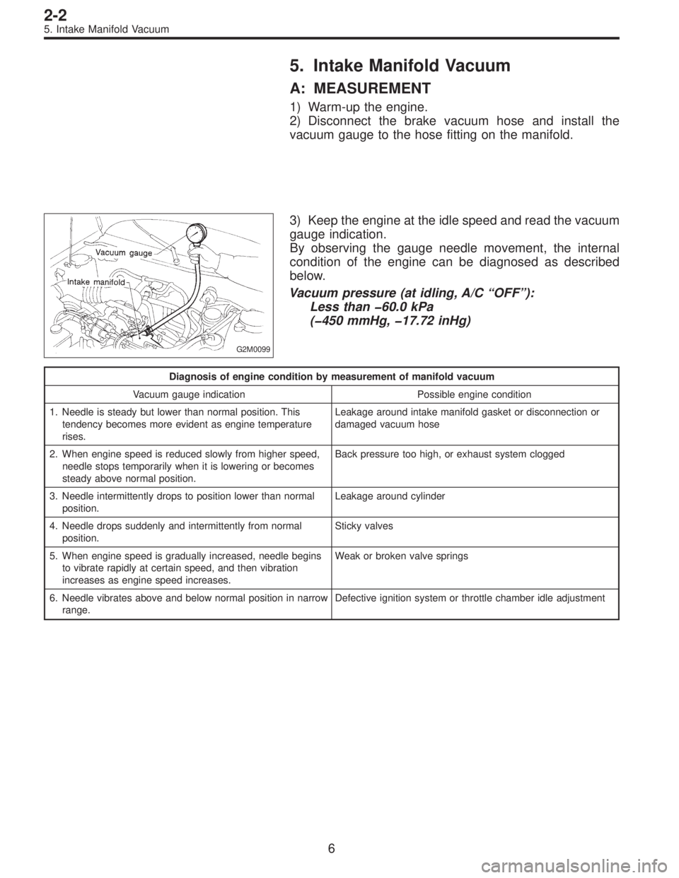
2) Disconnect the brake vacuum hose and install the
vacuum gauge to the hose fitting on the manifold.
G2M0099
3) Keep the engine at the idle speed and read the vacuum
gauge indication.
By observing the gauge needle movement, the internal
condition of the engine can be diagnosed as described
below.
Vacuum pressure (at idling, A/C“OFF”):
Less than �60.0 kPa
(�450 mmHg, �17.72 inHg)
Diagnosis of engine condition by measurement of manifold vacuum
Vacuum gauge indication Possible engine condition
1. Needle is steady but lower than normal position. This
tendency becomes more evident as engine temperature
rises.Leakage around intake manifold gasket or disconnection or
damaged vacuum hose
2. When engine speed is reduced slowly from higher speed,
needle stops temporarily when it is lowering or becomes
steady above normal position.Back pressure too high, or exhaust system clogged
3. Needle intermittently drops to position lower than normal
position.Leakage around cylinder
4. Needle drops suddenly and intermittently from normal
position.Sticky valves
5. When engine speed is gradually increased, needle begins
to vibrate rapidly at certain speed, and then vibration
increases as engine speed increases.Weak or broken valve springs
6. Needle vibrates above and below normal position in narrow
range.Defective ignition system or throttle chamber idle adjustment
6
2-2
5. Intake Manifold Vacuum
Page 97 of 2248

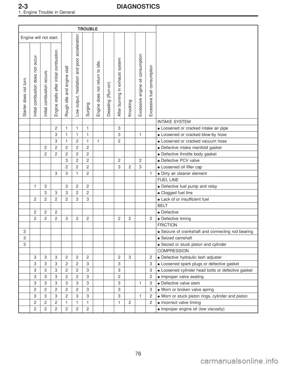
TROUBLE
Engine will not start.
Rough idle and engine stall
Low output, hesitation and poor acceleration
Surging
Engine does not return to idle.
Dieseling (Run-on)
After burning in exhaust system
Knocking
Excessive engine oil consumption
Excessive fuel consumption Starter does not turn.
Initial combustion does not occur.
Initial combustion occurs.
Engine stalls after initial combustion.
INTAKE SYSTEM
2111 3�Loosened or cracked intake air pipe
3111 3 1�Loosened or cracked blow-by hose
31211 2�Loosened or cracked vacuum hose
22222�Defective intake manifold gasket
22222�Defective throttle body gasket
322 2 2�Defective PCV valve
222 323�Loosened oil filler cap
3312 1�Dirty air cleaner element
FUEL LINE
13 322�Defective fuel pump and relay
33322�Clogged fuel line
222233�Lack of or insufficient fuel
BELT
222�Defective
222322 22 2�Defective timing
FRICTION
3�Seizure of crankshaft and connecting rod bearing
3�Seized camshaft
3�Seized or stuck piston and cylinder
COMPRESSION
333222 23 2�Defective hydraulic lash adjuster
333223 3 3�Loosened spark plugs or defective gasket
333223 3 3�Loosened cylinder head bolts or defective gasket
333223 2 2�Improper valve seating
333333 3 13�Defective valve stem
222223 3 3�Worn or broken valve spring
333233 3 12�Worn or stuck piston rings, cylinder and piston
222111 12 2�Incorrect valve timing
222222�Improper engine oil (low viscosity)
76
2-3DIAGNOSTICS
1. Engine Trouble in General
Page 153 of 2248

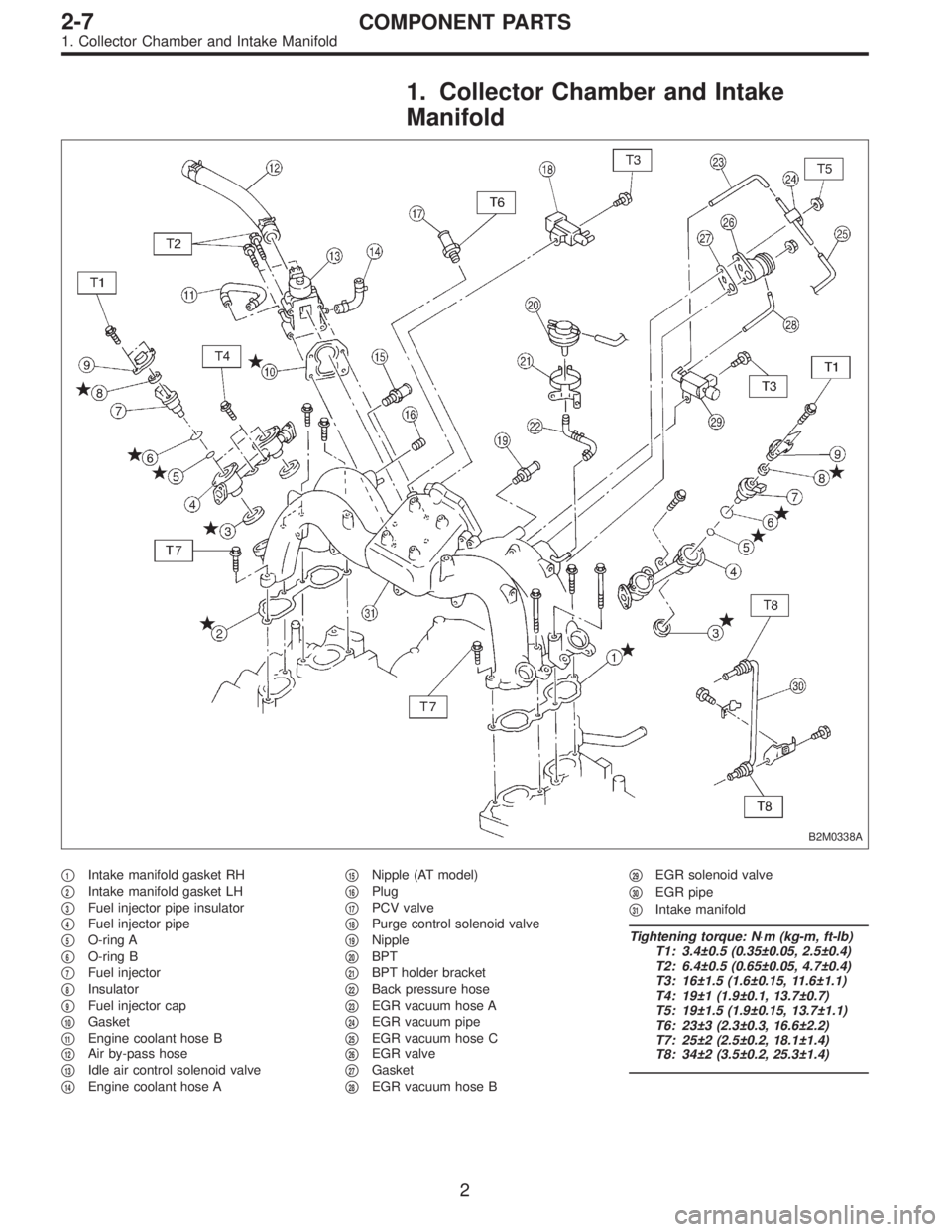
1. Collector Chamber and Intake
Manifold
B2M0338A
�1Intake manifold gasket RH
�
2Intake manifold gasket LH
�
3Fuel injector pipe insulator
�
4Fuel injector pipe
�
5O-ring A
�
6O-ring B
�
7Fuel injector
�
8Insulator
�
9Fuel injector cap
�
10Gasket
�
11Engine coolant hose B
�
12Air by-pass hose
�
13Idle air control solenoid valve
�
14Engine coolant hose A�
15Nipple (AT model)
�
16Plug
�
17PCV valve
�
18Purge control solenoid valve
�
19Nipple
�
20BPT
�
21BPT holder bracket
�
22Back pressure hose
�
23EGR vacuum hose A
�
24EGR vacuum pipe
�
25EGR vacuum hose C
�
26EGR valve
�
27Gasket
�
28EGR vacuum hose B�
29EGR solenoid valve
�
30EGR pipe
�
31Intake manifold
Tightening torque: N⋅m (kg-m, ft-lb)
T1: 3.4±0.5 (0.35±0.05, 2.5±0.4)
T2: 6.4±0.5 (0.65±0.05, 4.7±0.4)
T3: 16±1.5 (1.6±0.15, 11.6±1.1)
T4: 19±1 (1.9±0.1, 13.7±0.7)
T5: 19±1.5 (1.9±0.15, 13.7±1.1)
T6: 23±3 (2.3±0.3, 16.6±2.2)
T7: 25±2 (2.5±0.2, 18.1±1.4)
T8: 34±2 (3.5±0.2, 25.3±1.4)
2
2-7COMPONENT PARTS
1. Collector Chamber and Intake Manifold
Page 166 of 2248
B2M0019
8) Connect engine harness connector to bulkhead har-
ness connectors.
G2M0370
9) Connect canister hoses.
B2M0342
10) Connect brake booster vacuum hose.
H2M1259A
11) Connect engine coolant hose�1to idle air control sole-
noid valve.
12) Connect air by-pass hose�
2to idle air control solenoid
valve.
H2M1246
13) Connect engine coolant hoses to throttle body.
15
2-7SERVICE PROCEDURE
4. Intake Manifold
Page 192 of 2248
B2M0049
11) On AWD model, after removing fuel sub meter unit,
drain fuel from there.
WARNING:
Do not use a motor pump when draining fuel.
2. On-Car Services
A: MEASUREMENT OF FUEL PRESSURE
1) Release fuel pressure.
2) Connect connector to fuel pump.
G2M0347
3) Disconnect fuel delivery hoses from fuel filter, and con-
nect fuel pressure gauge.
G2M0348
4) Start the engine.
5) Measure fuel pressure while disconnecting pressure
regulator vacuum hose from collector chamber.
Fuel pressure:
235 — 265 kPa (2.4 — 2.7 kg/cm
2, 34 — 38 psi)
6) After connecting pressure regulator vacuum hose, mea-
sure fuel pressure.
Fuel pressure:
177 — 206 kPa (1.8 — 2.1 kg/cm
2, 26 — 30 psi)
WARNING:
Before removing fuel pressure gauge, release fuel
pressure.
NOTE:
If out of specification as measured at step 6), check or
replace pressure regulator and pressure regulator vacuum
hose.
8
2-8SERVICE PROCEDURE
1. Precautions - 2. On-Car Services