Page 762 of 2248
 Start engine and keep it running un")
G4M0423
5. CHECKING WITH GAUGES
Connect gauges as shown in Figure. After bleeding air from
pressure gauges, proceed to each check.
G4M0746
6. AIR TIGHTNESS CHECK
1) Start engine and keep it running until a vacuum of 66.7
kPa (500 mmHg, 19.69 inHg) = point A is indicated on
vacuum gauge. Do not depress brake pedal.
2) Stop engine and watch the gauge. If the vacuum drop
range is less than 3.3 kPa (25 mmHg, 0.98 inHg) within 15
seconds after stopping engine, brake booster is functioning
properly.
If defective, the cause may be one of those listed below.
�Check valve malfunction
�Leak from vacuum hose
�Leak from the shell jointed portion or stud bolt welded
portion
�Damaged diaphragm
�Leak from valve body seal and bearing portion
�Leak from plate and seal assembly portion
�Leak from poppet valve assembly portion
G4M0747
7. LOADED AIR TIGHTNESS CHECK
1) Start engine and depress brake pedal with pedal force
of 196 N (20 kg, 44 lb). Keep engine running until a vacuum
of 66.7 kPa (500 mmHg, 19.69 inHg) = point B is indicated
on vacuum gauge while the pedal is still depressed.
2) Stop engine and watch vacuum gauge.
If the vacuum drop range is less than 3.3 kPa (25 mmHg,
0.98 inHg) within 15 seconds after stopping engine, brake
booster is functioning properly.
If defective, refer to“AIR TIGHTNESS CHECK”described
above.
46
4-4SERVICE PROCEDURE
6. Brake Booster
Page 763 of 2248

8. LACK OF BOOSTING ACTION CHECK
Turn off engine, and set the vacuum gauge reading at“0”.
Then, check the fluid pressure when brake pedal is
depressed. The pressure must be greater than the stan-
dard value listed below.
Brake pedal force 147N (15 kg, 33 lb) 294N (30kg, 66 lb)
Models without ABS and
TCS785 kPa
(8 kg/cm
2, 114 psi)2,158 kPa
(22 kg/cm2, 313 psi)
Models with ABS and
TCS588 kPa
(6 kg/cm
2, 85 psi)1,667 kPa
(17 kg/cm2, 242 psi)
9. BOOSTING ACTION CHECK
Set the vacuum gauge reading at 66.7 kPa (500 mmHg,
19.69 inHg) by running engine. Then, check the fluid pres-
sure when brake pedal is depressed. The pressure must
be greater than the standard value listed below.
Brake pedal force 147N (15 kg, 33 lb) 294N (30kg, 66 lb)
Models without ABS and
TCS5,492 kPa
(56 kg/cm
2, 796 psi)8,434 kPa
(86 kg/cm2, 1,223 psi)
Models with ABS and
TCS5,394 kPa
(55 kg/cm
2,782 psi)10,003 kPa
(102 kg/cm2, 1,450
psi)
D: HANDLING PRECAUTIONS
1) Be careful not to drop brake booster. Brake booster
should be discarded if it has been dropped.
2) Use special care when handling operating rod.
If excessive force is applied to operating rod, sufficient to
cause a change in the angle in excess of ±3°, it may result
in damage to the power piston cylinder.
47
4-4SERVICE PROCEDURE
6. Brake Booster
Page 871 of 2248
 The combination of moisture and refrigerant forms acid,
therefore, moisture should not be allowed to enter the
refrigerant.
2) Refrigerant oil readily absorbs moisture, therefo")
2. Basic Information
1) The combination of moisture and refrigerant forms acid,
therefore, moisture should not be allowed to enter the
refrigerant.
2) Refrigerant oil readily absorbs moisture, therefore, keep
refrigerant oil containers tightly capped.
3) The process of evacuating the system is performed to
remove small amounts of moisture. This is accomplished
by lowering the pressure inside the system, which allows
the moisture to boil off, in much the same way that a pot
of water will boil away to nothing given enough time. The
evacuation process does not suck the moisture out of the
system.
4) A minimum level of vacuum must be reached to satis-
factorily evacuate the system. This minimum level of
vacuum depends on the temperature inside the system.
The chart below shows the level of vacuum required to boil
water at various temperatures.
Additionally, the vacuum level shown on a gauge will read
approx. 4 kPa (25 mmHg, 1 inHg) less for each 304.8 m
(1,000 ft) above sea level, due to the decrease in atmo-
spheric pressure at altitude.
Vacuum level required to boil water (at sea level)
Temperature°C(°F) Vacuum kPa (mmHg, inHg)
1.7 (35) 100.9 (757, 29.8)
7.2 (45) 100.6 (754, 29.7)
12.8 (55) 99.9 (749, 29.5)
18.3 (65) 99.2 (744, 29.3)
23.9 (75) 98.5 (739, 29.1)
29.4 (85) 97.2 (729, 28.7)
35 (95) 95.8 (719, 28.3)
11
4-7SERVICE PROCEDURE
2. Basic Information
Page 873 of 2248
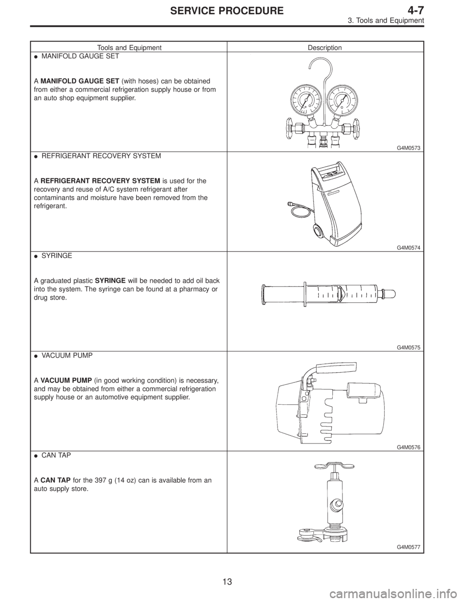
Tools and Equipment Description
�MANIFOLD GAUGE SET
AMANIFOLD GAUGE SET(with hoses) can be obtained
from either a commercial refrigeration supply house or from
an auto shop equipment supplier.
G4M0573
�REFRIGERANT RECOVERY SYSTEM
AREFRIGERANT RECOVERY SYSTEMis used for the
recovery and reuse of A/C system refrigerant after
contaminants and moisture have been removed from the
refrigerant.
G4M0574
�SYRINGE
A graduated plasticSYRINGEwill be needed to add oil back
into the system. The syringe can be found at a pharmacy or
drug store.
G4M0575
�VACUUM PUMP
AVACUUM PUMP(in good working condition) is necessary,
and may be obtained from either a commercial refrigeration
supply house or an automotive equipment supplier.
G4M0576
�CAN TAP
ACAN TAPfor the 397 g (14 oz) can is available from an
auto supply store.
G4M0577
13
4-7SERVICE PROCEDURE
3. Tools and Equipment
Page 879 of 2248
 Be certain that goggles and gloves are worn.
2) If bulk refr")
G4M0596
7. Evacuating and Charging
The following points should be kept in mind when evacu-
ating and charging with a manifold gauge set.
1) Be certain that goggles and gloves are worn.
2) If bulk refrigerant [13.6 kg (30 lb) canister] is used, be
certain to weigh the charge amount carefully, using the
correct equipment, to avoid overcharging the system.
3) The charging procedure described in this section
begins by chargingliquidrefrigerant into the high- pres-
sure side of the systemwith the engine off.The proce-
dure is completed by charging refrigerantvaporinto the
low-pressure side of the system with the engine running.
CAUTION:
Never open the high-pressure manifold valve when the
engine is running.
G4M0597
1. CONNECT THE GAUGE SET
1) Close the high- and low-pressure manifold valves.
2) Attach the low-pressure manifold hose to the low- pres-
sure service port on the vehicle. Check the low- pressure
gauge. If more than 68.6 kPa (0.70 kg/cm
2, 10 psi) is
indicated, discharge the system prior to charging.
3) Attach the high-pressure manifold hose to the high-
pressure service port on the vehicle.
4) Connect the center hose from the manifold to the
vacuum pump.
5) Turn on the vacuum pump.
6) Slowly open the low-pressure manifold valve.
7) When the low-pressure gauge reaches approximately
66.43 kPa (498.3 mmHg, 19.62 inHg), slowly open the
high-pressure manifold valve.
G4M0598
8) Maintain a minimum vacuum level of 100.56 kPa (754.4
mmHg, 29.70 inHg) for a minimum of 15 minutes on a new
system or 30 minutes for an in-service system.
NOTE:
The gauge will read 4 kPa (25 mmHg, 1 inHg) less for
every 304.8 m (1,000 ft) above sea level.
19
4-7SERVICE PROCEDURE
7. Evacuating and Charging
Page 880 of 2248
 After 15 minutes (or more) of evacuation, close the
high-pressure manifold valve.
2) Close the low-pressure manifold valve.
3) Turn off the vacuum pump.
G4M060")
G4M0599
2. PERFORM A VACUUM LEAK TEST
1) After 15 minutes (or more) of evacuation, close the
high-pressure manifold valve.
2) Close the low-pressure manifold valve.
3) Turn off the vacuum pump.
G4M0600
4) Note the low side gauge reading.
5) After 5 minutes, re-check the low-pressure gauge read-
ing.
If the vacuum level has changed more than 4 kPa (25
mmHg, 1 inHg), perform an HFC-134a leak test.
If the vacuum reading is about the same as noted in step
2-4), continue on to step 2-6).
G4M0980
6) Carefully attach the can tap to the refrigerant can by
following the can tap manufacturer’s instructions.
7) Disconnect the center manifold hose from the vacuum
pump and connect the hose to the tap valve.
G4M0981
8) If a 13.6 kg (30 lb) container of refrigerant is used a
weight scale will be needed. This scale is to determine the
amount of refrigerant that is used.
Connect the center hose from the manifold to the valve.
Place the 13.6 kg (30 lb) container on the scale, valve end
down.
G4M0603
3. PURGE THE CENTER HOSE
1) Verify that all three hose connections are tight at the
manifold gauge set.
2) Open the valve on the HFC-134a source.
3)With safety equipment in place (goggles and
gloves), use extreme cautionand loosen the center hose
connection at the manifold and allow the HFC-134a to
escape for no more than two or three seconds, then quickly
retighten the hose fitting at the manifold.
20
4-7SERVICE PROCEDURE
7. Evacuating and Charging
Page 907 of 2248

Condition Probable cause Corrective action
G4M0676
G4M0677
Insufficient cooling;
Sweated suction line.
No cooling;
Sweating or frosted suc-
tion line.Expansion valve allows
too much refrigerant
through evaporator.
Faulty seal of O-ring in
expansion valve.Check valve for opera-
tion. If suction side does
not show a pressure
decrease, replace valve.
1. Discharge system.
2. Remove expansion
valve and replace
O-ring.
3. Evacuate and
replace system.
AIR IN SYSTEM
G4M0678
Insufficient cooling Air mixed with refriger-
ant in system.1. Discharge system.
2. Replace receiver
drier.
3. Evacuate and charge
system.
MOISTURE IN SYSTEM
G4M0679
After operation for a
while, pressure on suc-
tion side may show
vacuum pressure read-
ing. During this
condition, discharge air
will be warm. As warn-
ing of this, reading
shows 39 kPa (0.4
kg/cm
2, 6 psi) vibration.Drier is saturated with
moisture. Moisture has
frozen at expansion
valve. Refrigerant flow
is restricted.1. Discharge system.
2. Replace receiver
drier (twice if neces-
sary).
3. Evacuate system
completely. (repeat
30-minute evacuating
three times.)
4. Recharge system.
45
4-7DIAGNOSTICS
2. Performance Test Diagnosis
Page 1153 of 2248
 Remove nuts which secure actuator.
4) Remove actuator while disconnecting vacuum hose.
Tightening torque:
7.4±1.5 N⋅m (0.75±0.15 kg-m, 5.4±1.1 ft-lb)
B6M0359A
4. VACUUM PUMP AND VALVES")
B6M0358
3) Remove nuts which secure actuator.
4) Remove actuator while disconnecting vacuum hose.
Tightening torque:
7.4±1.5 N⋅m (0.75±0.15 kg-m, 5.4±1.1 ft-lb)
B6M0359A
4. VACUUM PUMP AND VALVES
1) Disconnect connector from vacuum pump.
2) Remove bolts which secure vacuum pump.
3) Remove A/C receiver/drier bracket.
4) Remove vacuum pump while disconnecting vacuum
hose.
Tightening torque:
7.4±1.5 N⋅m (0.75±0.15 kg-m, 5.4±1.1 ft-lb)
5. STOP AND BRAKE SWITCH
Refer to 4-5 [C101 (MT) or C201 (AT)] as for removal and
installation of stop and brake switch.
6. CLUTCH SWITCH (MT)
Refer to 4-5 [C101] as for removal and installation of clutch
switch.
7. INHIBITOR SWITCH (AT)
Refer to 3-2 [W4A4] as for removal and installation of
inhibitor switch.
B6M0360A
8. CRUISE CONTROL MODULE
1) Follow the same preparatory procedures when remov-
ing door lock timer.
2) Remove nuts which secure cruise control module, and
remove cruise control module from bracket while pulling
right side lower end of instrument panel.
CAUTION:
Be careful not to damage instrument panel while pull-
ing its right side lower end.
3) Disconnect connector from cruise control module.
4) Installation is the reverse order of removal.
49
6-2SERVICE PROCEDURE
21. Cruise Control