Page 1357 of 2248
OBD0170
E: DTC P0106
—PRESSURE SENSOR CIRCUIT
RANGE/PERFORMANCE PROBLEM (P
—R)—
DESCRIPTION:
Refer to“D: DTC P0105—PRESSURE SENSOR CIR-
CUIT MALFUNCTION—[T11D0]”.
DTC DETECTING CONDITION:
�Two consecutive trips with fault
1.Check transmission type.
AT
�MT
Check AT/MT identification circuit.
2.Check DTC P0105 or P1102 on display.
No
�Ye s
�Inspect DTC P0105 or P1102 using“11. Diagnostics
Chart with Trouble Code [T1100]”.
�In this case, it is unnecessary to inspect DTC
P0106.
3.Check data for control.
4.Check vacuum hose.
5.Check pressure sources of switching solenoid
valve.
CAUTION:
After repair or replacement of faulty parts, conduct
CLEAR MEMORY and INSPECTION MODES.
[T3D0] and [T3E0].>
�
�
�
�
151
2-7ON-BOARD DIAGNOSTICS II SYSTEM
11. Diagnostics Chart with Trouble Code
Page 1361 of 2248
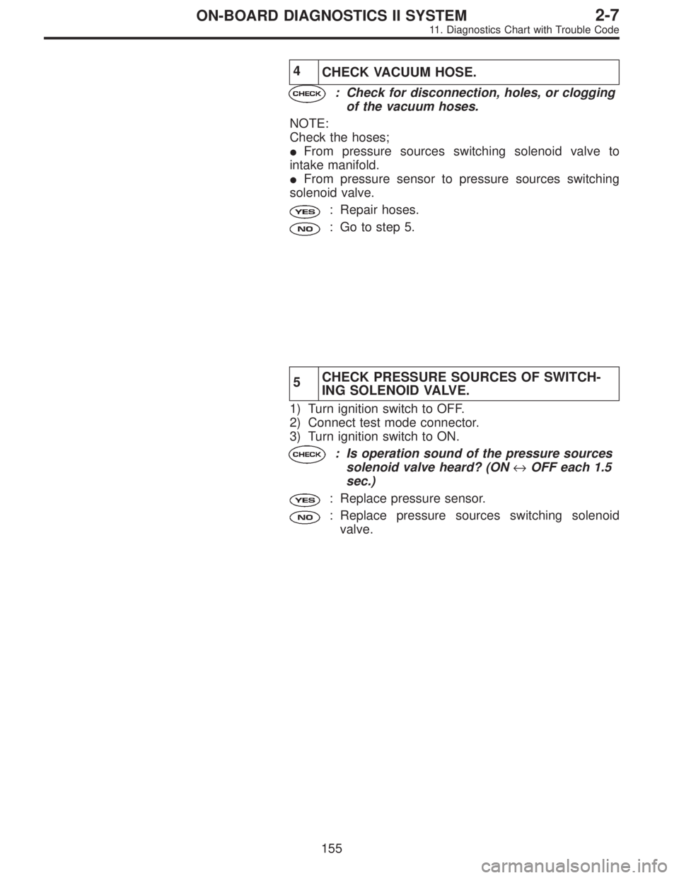
4
CHECK VACUUM HOSE.
: Check for disconnection, holes, or clogging
of the vacuum hoses.
NOTE:
Check the hoses;
�From pressure sources switching solenoid valve to
intake manifold.
�From pressure sensor to pressure sources switching
solenoid valve.
: Repair hoses.
: Go to step 5.
5CHECK PRESSURE SOURCES OF SWITCH-
ING SOLENOID VALVE.
1) Turn ignition switch to OFF.
2) Connect test mode connector.
3) Turn ignition switch to ON.
: Is operation sound of the pressure sources
solenoid valve heard? (ON↔OFF each 1.5
sec.)
: Replace pressure sensor.
: Replace pressure sources switching solenoid
valve.
155
2-7ON-BOARD DIAGNOSTICS II SYSTEM
11. Diagnostics Chart with Trouble Code
Page 1406 of 2248
 Disconnect fuel delivery hose from fuel filter, and con-
nect fuel pressure gauge.
G2M0348
4) Start the engine and idle while gear position is neutral.
5) Measure fuel pressure while discon")
OBD0711
3) Disconnect fuel delivery hose from fuel filter, and con-
nect fuel pressure gauge.
G2M0348
4) Start the engine and idle while gear position is neutral.
5) Measure fuel pressure while disconnecting pressure
regulator vacuum hose from intake manifold.
: Fuel pressure:
226—275 kPa (2.3—2.8 kg/cm2,
33—40 psi)
: Go to next step.
: Repair the following items.
Fuel pressure too high�Clogged fuel return line or bent
hose
Fuel pressure too low�Improper fuel pump discharge
�Clogged fuel supply line
6) After connecting pressure regulator vacuum hose, mea-
sure fuel pressure.
: Fuel pressure:
157—206 kPa (1.6—2.1 kg/cm2,
23—30 psi)
: Go to step 4.
: Repair the following items.
Fuel pressure too high�Faulty pressure regulator
�Clogged fuel return line or bent
hose
Fuel pressure too low�Faulty pressure regulator
�Improper fuel pump discharge
�Clogged fuel supply line
WARNING:
Before removing fuel pressure gauge, release fuel
pressure.
NOTE:
�If fuel pressure does not increase, squeeze fuel return
hose 2 to 3 times, then measure fuel pressure again.
�If out of specification as measured at step 6), check or
replace pressure regulator and pressure regulator vacuum
hose.
200
2-7ON-BOARD DIAGNOSTICS II SYSTEM
11. Diagnostics Chart with Trouble Code
Page 1435 of 2248
OBD0315
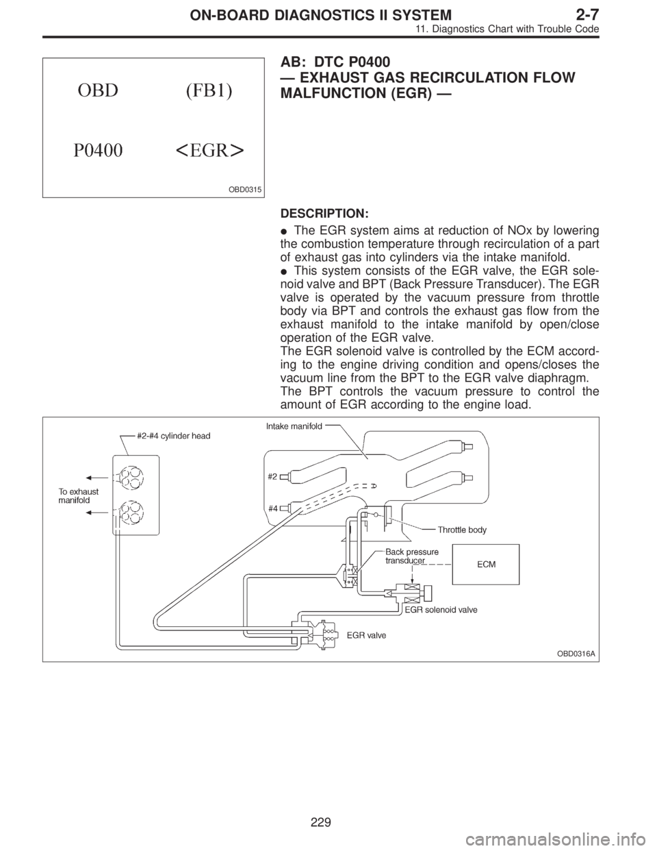
AB: DTC P0400
—EXHAUST GAS RECIRCULATION FLOW
MALFUNCTION (EGR)—
DESCRIPTION:
�The EGR system aims at reduction of NOx by lowering
the combustion temperature through recirculation of a part
of exhaust gas into cylinders via the intake manifold.
�This system consists of the EGR valve, the EGR sole-
noid valve and BPT (Back Pressure Transducer). The EGR
valve is operated by the vacuum pressure from throttle
body via BPT and controls the exhaust gas flow from the
exhaust manifold to the intake manifold by open/close
operation of the EGR valve.
The EGR solenoid valve is controlled by the ECM accord-
ing to the engine driving condition and opens/closes the
vacuum line from the BPT to the EGR valve diaphragm.
The BPT controls the vacuum pressure to control the
amount of EGR according to the engine load.
OBD0316A
229
2-7ON-BOARD DIAGNOSTICS II SYSTEM
11. Diagnostics Chart with Trouble Code
Page 1436 of 2248
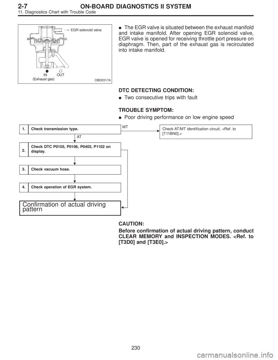
OBD0317A
�The EGR valve is situated between the exhaust manifold
and intake manifold. After opening EGR solenoid valve,
EGR valve is opened for receiving throttle port pressure on
diaphragm. Then, part of the exhaust gas is recirculated
into intake manifold.
DTC DETECTING CONDITION:
�Two consecutive trips with fault
TROUBLE SYMPTOM:
�Poor driving performance on low engine speed
1.Check transmission type.
AT
�MT
Check AT/MT identification circuit.
[T11BN0].>
2.Check DTC P0105, P0106, P0403, P1102 on
display.
�
3.Check vacuum hose.
4.Check operation of EGR system.
Confirmation of actual driving
pattern
CAUTION:
Before confirmation of actual driving pattern, conduct
CLEAR MEMORY and INSPECTION MODES.
[T3D0] and [T3E0].>
�
�
�
�
230
2-7ON-BOARD DIAGNOSTICS II SYSTEM
11. Diagnostics Chart with Trouble Code
Page 1439 of 2248

3
CHECK VACUUM HOSE.
: Check vacuum hoses for disconnection,
leakage and clogging.
: Check and repair the following items.
�Two lines of pipes and hoses running between
throttle body and BPT
�Pipe and hose line connecting BPT and EGR
solenoid valve
�Hose between EGR solenoid valve and EGR
valve
�BPT pressure transmitting hose
: Go to step 4.
4
CHECK OPERATION OF EGR SYSTEM.
1) Turn ignition switch to OFF.
2) Connect the test mode connector.
3) Turn ignition switch to ON.
: Does EGR solenoid valve produce operating
sound?
: Replace EGR solenoid valve.
: Go to next step.
4) Turn ignition switch to OFF.
5) Disconnect connector from EGR solenoid valve.
6) Connect 12 V battery’s ground�terminal to one ter-
minal of the EGR solenoid valve. Then connect 12 V bat-
tery’s�terminal to the other terminal of it.
CAUTION:
Do not use the 12 V battery installed in the vehicle,
because the electrical system may be damaged.
7) Start the engine.
: Open throttle valve by 5 to 10 degrees and
visually check EGR valve operation.
: Possibly EGR valve malfunction may be due to
freezing or clogging by foreign matter. At this point
in time do not replace EGR valve, since it is not
faulty. And after the checking, go to
CONFIR-
MATION OF ACTUAL DRIVING PATTERN.
NOTE:
If malfunction is detected again in the confirmation of actual
driving pattern, EGR valve is faulty. Go to next
.
: Go to next.
233
2-7ON-BOARD DIAGNOSTICS II SYSTEM
11. Diagnostics Chart with Trouble Code
Page 1465 of 2248
 Turn ignition switch to ON.
2) Start engine, and idle it.
3) Check intake manifold, idle air control solenoid valve
and throttle body for loose installation and gasket fo")
1
CHECK AIR INTAKE SYSTEM.
1) Turn ignition switch to ON.
2) Start engine, and idle it.
3) Check intake manifold, idle air control solenoid valve
and throttle body for loose installation and gasket for
cracks.
4) Check by-pass hoses for loose connections and cracks.
5) Check vacuum hoses for disconnections.
OBD0362A
2
CHECK OUTPUT SIGNAL FROM ECM.
1) Turn ignition switch to ON.
2) Measure voltage between ECM and body.
: Connector & terminal
(B84) No. 11—Body / 3 V, or more
(B84) No. 12—Body / 3 V, or more
: Go to step 4.
: Go to the next step.
OBD0362A
3) Turn ignition switch to OFF.
4) Disconnect connector from idle air control solenoid
valve.
5) Turn ignition switch to ON.
6) Measure voltage between ECM and body.
: Connector & terminal
(B84) No. 11—Body / 10 V, or more
(B84) No. 12—Body / 10 V, or more
: Repair short circuit of harness and replace ECM.
: Go to next.
: Is there poor contact in ECM connector?
: Repair poor contact in ECM connector.
: Go to step 3.
259
2-7ON-BOARD DIAGNOSTICS II SYSTEM
11. Diagnostics Chart with Trouble Code
Page 1471 of 2248
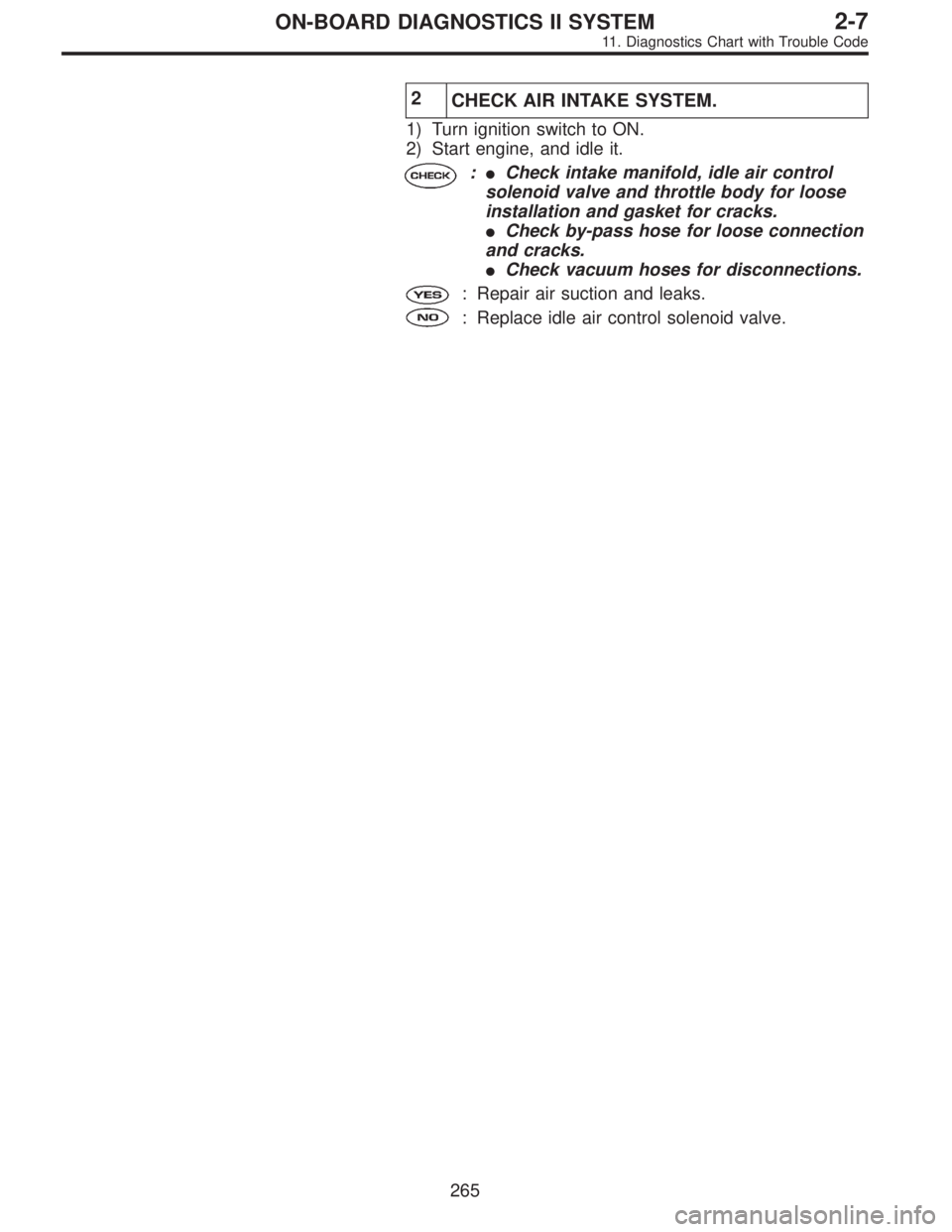
2
CHECK AIR INTAKE SYSTEM.
1) Turn ignition switch to ON.
2) Start engine, and idle it.
:�Check intake manifold, idle air control
solenoid valve and throttle body for loose
installation and gasket for cracks.
�Check by-pass hose for loose connection
and cracks.
�Check vacuum hoses for disconnections.
: Repair air suction and leaks.
: Replace idle air control solenoid valve.
265
2-7ON-BOARD DIAGNOSTICS II SYSTEM
11. Diagnostics Chart with Trouble Code
![SUBARU LEGACY 1995 Service Repair Manual OBD0170
E: DTC P0106
—PRESSURE SENSOR CIRCUIT
RANGE/PERFORMANCE PROBLEM (P
—R)—
DESCRIPTION:
Refer to“D: DTC P0105—PRESSURE SENSOR CIR-
CUIT MALFUNCTION—[T11D0]”.
DTC DETECTING CONDITION](/manual-img/17/57432/w960_57432-1356.png "SUBARU LEGACY 1995 Service Repair Manual OBD0170
E: DTC P0106
—PRESSURE SENSOR CIRCUIT
RANGE/PERFORMANCE PROBLEM (P
—R)—
DESCRIPTION:
Refer to“D: DTC P0105—PRESSURE SENSOR CIR-
CUIT MALFUNCTION—[T11D0]”.
DTC DETECTING CONDITION")