Page 1856 of 2248
B6M0269A
2. VACUUM HOSE AND PIPE
Check vacuum hose and pipe (which connects actuator
and vacuum pump) for disconnection or cracks.
B6M0270A
3. ACTUATOR
1) Disconnect vacuum hose from actuator.
B6M0174
2) Connect vacuum pump as shown in figure.
3) Make sure that cruise control cable moves smoothly
and quickly when a vacuum pressure of 40.0 kPa (300
mmHg, 11.81 inHg) is applied to actuator.
Stroke: 35 mm (1.38 in)
4) When vacuum pressure is released from condition 3)
above, make sure the cable returns to its original position
smoothly and quickly.
5) After inspection, disconnect vacuum pump and connect
vacuum hose.
4. POWER SUPPLY
1) Measure battery voltage and specific gravity of electro-
lyte.
Standard voltage: 12 V
Specific gravity: Above 1.260
2) Check the condition of the main and other fuses, and
harnesses and connectors. Also check for proper ground-
ing.
3
6-2BODY ELECTRICAL SYSTEM
2. Pre-inspection
Page 1857 of 2248
 Measure resistance of vacuum pump and valve.
(1) Disconnect connector from vacuum pump and valve.
(2) Measure resistance between each terminal of
vacuum pump and va")
B6M0271
5. VACUUM PUMP AND VALVE
1) Measure resistance of vacuum pump and valve.
(1) Disconnect connector from vacuum pump and valve.
(2) Measure resistance between each terminal of
vacuum pump and valve.
Terminals / Specified resistance:
No. 2—No. 3 / 100Ωor less (Vacuum pump
motor)
No. 2—No. 1 / 69Ω(Air valve)
No. 2—No. 4 / 69Ω(Release valve)
B6M0272
2) Check for leakage and sticking of vacuum valve.
(1) Disconnect connector from vacuum pump and valve.
(2) Make sure that cruise control cable moves smoothly
when connecting + (positive) battery cable to terminal
No. 2 and � (negative) battery cable to terminals No. 1,
3 and 4 of vacuum pump and valve connector.
Stroke: 35 mm (1.38 in)
Movement time: Within 3 seconds
(3) When the battery cable is disconnected from condi-
tion (2) above, make sure the cable returns to its origi-
nal position smoothly.
Movement time: Within 1.5 seconds
(4) Connect battery to each terminal and check cable
movement.
Terminal No. Battery
Cruise control
cable operation
1234��
———————
��
Pull ����
��
��
Hold ��
��
��Release
��
4
6-2BODY ELECTRICAL SYSTEM
2. Pre-inspection
Page 1858 of 2248
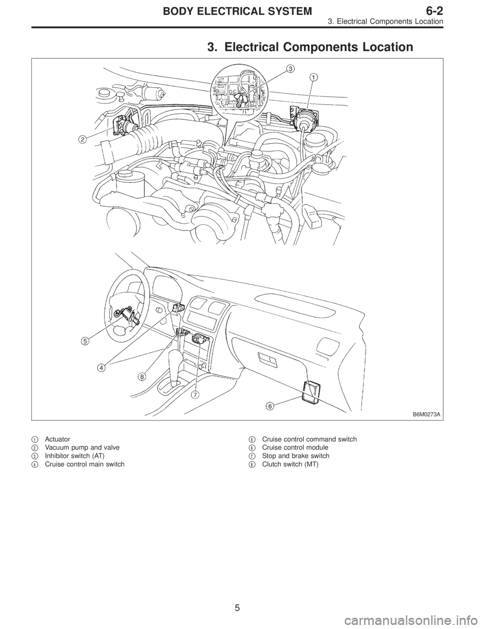
3. Electrical Components Location
B6M0273A
�1Actuator
�
2Vacuum pump and valve
�
3Inhibitor switch (AT)
�
4Cruise control main switch�
5Cruise control command switch
�
6Cruise control module
�
7Stop and brake switch
�
8Clutch switch (MT)
5
6-2BODY ELECTRICAL SYSTEM
3. Electrical Components Location
Page 1860 of 2248

Main power supply 2�Battery voltage is present when main power is tu")
5. Control Module I/O Signal
G6M0015
ContentTerminal
No.Measuring conditions and I/O signals (ignition switch ON and engine idling)
Main power supply 2�Battery voltage is present when main power is turned ON.
�“0”volt is present when main power is turned OFF.
Inhibitor switch (AT) (U.S.A.)
N position switch (AT) (CANADA)4�“0”volt is present when selector lever is set to P or N position (CANADA: N position only).
�Battery voltage is present when selector lever is other than P or N position (CANADA: N
position only).
Air valve 5�“0”volt is present when vehicle is stopped.
�ON-and-OFF (“0”-and-battery voltage) operation is alternately repeated while cruise control
is operating.
GND 6—
Vacuum pump motor 7�“0”volt is present when vehicle is stopped.
�ON-and-OFF (“0”-and-battery voltage) operation is alternately repeated while cruise control
is operating.
Data link connector 8—
RESUME/ACCEL switch 9�Battery voltage is present when switch is turned ON.
�“0”volt is present when switch is turned OFF.
SET/COAST switch 10�Battery voltage is present when switch is turned ON.
�“0”volt is present when switch is turned OFF.
Ignition switch 12�Battery voltage is present when ignition switch is turned ON.
�“0”volt is present when ignition switch is turned OFF.
Release valve 13�“0”volt is present when vehicle is stopped.
�ON-and-OFF (“0”-and-battery voltage) operation is alternately repeated while cruise control
is operating.
Power supply to vacuum pump
motor, air valve, release valve14�“0”volt is present when vehicle is stopped.
�Battery voltage is present while cruise control is operating.
Cruise main switch 15�Battery voltage is present during pressing the main switch, and then approx. 12 V is
present while switch is turned ON.
�“0”volt is present when switch is turned OFF.
Brake switch 16Turn the cruise main switch to ON and leave clutch pedal released (MT).
Then check that;
�“0”volt is present when brake pedal is depressed.
�Battery voltage is present when brake pedal is released.
Additionally only in MT vehicle, keep the cruise main switch to ON and leave brake pedal
released.
Then check that;
�“0”volt is present when clutch pedal is depressed.
�Battery voltage is present when clutch pedal is released.
Data link connector 17—
Data link connector 18—
Vehicle speed sensor 2 19Lift-up the vehicle until all four wheels are raised off ground, and then rotate any wheel manu-
ally.
Approx. 5 and 0 volt pulse signals are alternately input to cruise control module.
Stop light switch 20Turn ignition switch to OFF.
Then check that;
�Battery voltage is present when brake pedal is depressed.
�“0”volt is present when brake pedal is released.
NOTE:
Voltage at terminals 5, 7, 13 and 14 cannot be checked unless vehicle is driving by cruise control operation.
7
6-2BODY ELECTRICAL SYSTEM
5. Control Module I/O Signal
Page 1861 of 2248
![SUBARU LEGACY 1995 Service Repair Manual 6. Diagnostics Chart for On-board
Diagnosis System
A: BASIC DIAGNOSTICS PROCEDURE
Trouble occurs.
Pre-inspection <Ref. to 6-2 [T200].>
Check if cruise control main switch turns ON prop-
erly.
OK
�Not](/manual-img/17/57432/w960_57432-1860.png "SUBARU LEGACY 1995 Service Repair Manual 6. Diagnostics Chart for On-board
Diagnosis System
A: BASIC DIAGNOSTICS PROCEDURE
Trouble occurs.
Pre-inspection <Ref. to 6-2 [T200].>
Check if cruise control main switch turns ON prop-
erly.
OK
�Not")
6. Diagnostics Chart for On-board
Diagnosis System
A: BASIC DIAGNOSTICS PROCEDURE
Trouble occurs.
Pre-inspection
Check if cruise control main switch turns ON prop-
erly.
OK
�Not OK
Diagnostics Chart for Power Line
[T700].>
(Main switch fails when turning to ON.)
Check if cruise speed is properly set while driving at
minimum of 40 km/h (25 MPH).
OK
�Not OK
Diagnostics Chart with Trouble Code
[T800].> (When cruise control cannot be set.)
Check if cruise control is properly released during
operation.
OK
�Not OK
Check if cruise speed is held within set speed ±3
km/h (±2 MPH).
OK
�Not OK
Basic inspection of actuator, vacuum pump and
valve (When is not running
at a fixed speed.)
Check if RESUME/ACCEL switch functions properly.
OK
�Not OK
Diagnostics Chart with Trouble Code
[T800].> (When cruise control cannot be set.)
Check if SET/COAST switch functions properly.
OK
�Not OK
Check if CANCEL switch functions properly. (Airbag
equipped model)
OK
�Not OK
Check if cruise speed is released when brake pedal
is depressed.
OK
�Not OK
Set cruise speed again. Check if cruise speed is
released when clutch pedal is depressed (MT
model) or when select lever is moved to“Neutral.”
OK
�Not OK
Cruise control system is in good order.
�
�
�
�
�
�
�
�
�
�
�
8
6-2BODY ELECTRICAL SYSTEM
6. Diagnostics Chart for On-board Diagnosis System
Page 1869 of 2248

8. Diagnostics Chart with Trouble Code
A: TROUBLE CODE
Trouble code Item Contents of diagnosis Page
10 OK Normal 18
11 BRAKE/ST/CL or N�Input signals from brake switch“OFF”, stop light
switch“ON”(Brake pedal is in depressed condi-
tion.)
�Input signals from clutch switch“OFF”, or inhibi-
tor switch is in“N”position.
[Clutch pedal is depressed (MT), or select lever
is set to N position (AT).]20
12 NOT SET SP Out of cruise speed range 22
13 LOW SP LIM Low-speed control limiter 22
14 CANCEL SW Input signal from cancel switch 26
15 NO MEMORY No memorized cruise speed—
21 SP SENS NG Faulty vehicle speed sensor 2 22
22 COM SW NGFaulty SET/COAST switch or RESUME/ACCEL
switch26
23 RELAY NG Faulty safety relay included in cruise control module 29
24 CPU RAM NG Faulty CPU RAM included in cruise control module 29
31 MOTOR NG Faulty vacuum motor or motor drive system 30
32 AIR VAL NG Faulty air valve or valve drive system 30
33 REL VAL NG Faulty release valve or valve drive system 30
16
6-2BODY ELECTRICAL SYSTEM
8. Diagnostics Chart with Trouble Code
Page 1882 of 2248
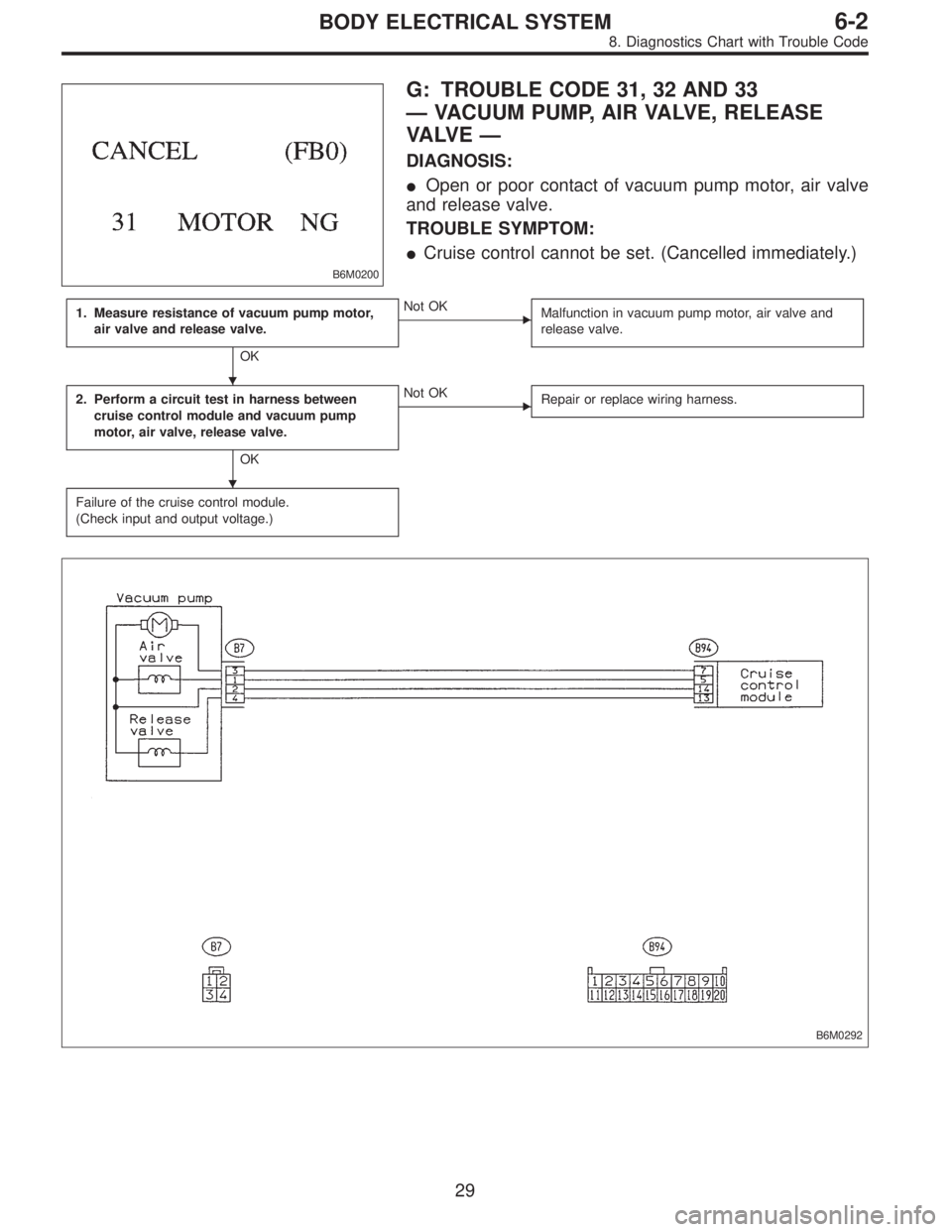
B6M0200
G: TROUBLE CODE 31, 32 AND 33
—VACUUM PUMP, AIR VALVE, RELEASE
VA LV E—
DIAGNOSIS:
�Open or poor contact of vacuum pump motor, air valve
and release valve.
TROUBLE SYMPTOM:
�Cruise control cannot be set. (Cancelled immediately.)
1. Measure resistance of vacuum pump motor,
air valve and release valve.
OK
�Not OK
Malfunction in vacuum pump motor, air valve and
release valve.
2. Perform a circuit test in harness between
cruise control module and vacuum pump
motor, air valve, release valve.
OK
�Not OK
Repair or replace wiring harness.
Failure of the cruise control module.
(Check input and output voltage.)
B6M0292
�
�
29
6-2BODY ELECTRICAL SYSTEM
8. Diagnostics Chart with Trouble Code
Page 1883 of 2248
B6M0271
1. MEASURE RESISTANCE OF VACUUM PUMP
MOTOR, AIR VALVE AND RELEASE VALVE.
1) Disconnect connector of vacuum pump and valve.
2) Measure resistance of vacuum pump motor, air valve
and release valve.
Terminals / Specified resistance:
No. 2—No. 3 / 46Ω(Vacuum pump motor)
No. 2—No. 1 / 69Ω(Air valve)
No. 2—No. 4 / 69Ω(Release valve)
B6M0293A
2. PERFORM A CIRCUIT TEST IN HARNESS
BETWEEN CRUISE CONTROL MODULE AND
VACUUM PUMP MOTOR, AIR VALVE, RELEASE
VA LV E .
1) Disconnect connectors from cruise control module,
vacuum pump and valve.
2) Measure resistance of harness connector between
cruise control module, vacuum pump motor, air valve and
release valve.
Connector & terminal / Specified resistance:
(B7) No. 1—(B94) No. 5 / 10Ω, max.
(B7) No. 2—(B94) No. 14 / 10Ω, max.
(B7) No. 3—(B94) No. 7 / 10Ω, max.
(B7) No. 4—(B94) No. 13 / 10Ω, max.
30
6-2BODY ELECTRICAL SYSTEM
8. Diagnostics Chart with Trouble Code
 for disconnection or cracks.
B6M0270A
3. ACTUATOR
1) Disconnect vacuum hose from actuator.
B6M0174")
 Disconnect connector of vacuum pump and valve.
2) Measure resistance of vacuum pump motor, air valve
and release val")