Page 347 of 2248

Automatic
transmis-
sionOil pumpType Variable-capacity type vane pump
Driving method Driven by engine
Number of vanes 9 pieces
Hydraulic
controlTypeElectronic/hydraulic control
[Four forward speed changes by electrical signals
of car speed and accelerator (throttle) opening]
Fluid Dexron II type Automatic transmission fluid
Fluid capacity 7.9�(8.4 US qt, 7.0 Imp qt)
LubricationLubrication system Forced feed lubrication with oil pump
Oil Automatic transmission fluid (above mentioned.)
Cooling Cooling system Liquid-cooled cooler incorporated in radiator
HarnessInhibitor switch 12 poles
Transmission harness polesFWD ... 11
AWD ... 13
TransferTransfer clutch Hydraulic multi-plate clutch
Control method Electronic, hydraulic type
LubricantThe same Automatic Transmission Fluid used in
automatic transmission.
1st reduction gear ratio 1.000 (53/53)
Final
reductionFinal gear
ratioFront driveFWD 3.900 (39/10)
AWD 4.111 (37/9)
Speedometer gear ratio 0.83 (19/23)
Lubrication oil API, GL-5
Oil
capacityFront drive 1.2�(1.3 US qt, 1.1 Imp qt)
AT F
cooling
systemRadiation capacity 1.651 kW (1,420 kcal/h, 5,635 BTU/h)
3
3-2SPECIFICATIONS AND SERVICE DATA
1. Automatic Transmission and Differential
Page 851 of 2248
1. Supplemental Restraint System
“Airbag”
Airbag system wiring harness is routed near the instrument
panel, heater unit, blower motor and control unit.
CAUTION:
�All Airbag system wiring harness and connectors
are colored yellow. Do not use electrical test equip-
ment on these circuit.
�Be careful not to damage Airbag system wiring har-
ness when servicing the instrument panel, heater unit,
blower motor and control unit.
2. Heater Unit
A: REMOVAL AND INSTALLATION
1) Disconnect GND cable from battery.
2) Remove heater hoses (inlet, outlet) in engine compart-
ment.
NOTE:
Drain as much coolant from heater unit as possible, and
plug disconnected hose with cloth.
3) Remove instrument panel.
4) Remove steering support beam.
5) Remove evaporator. (With A/C model)
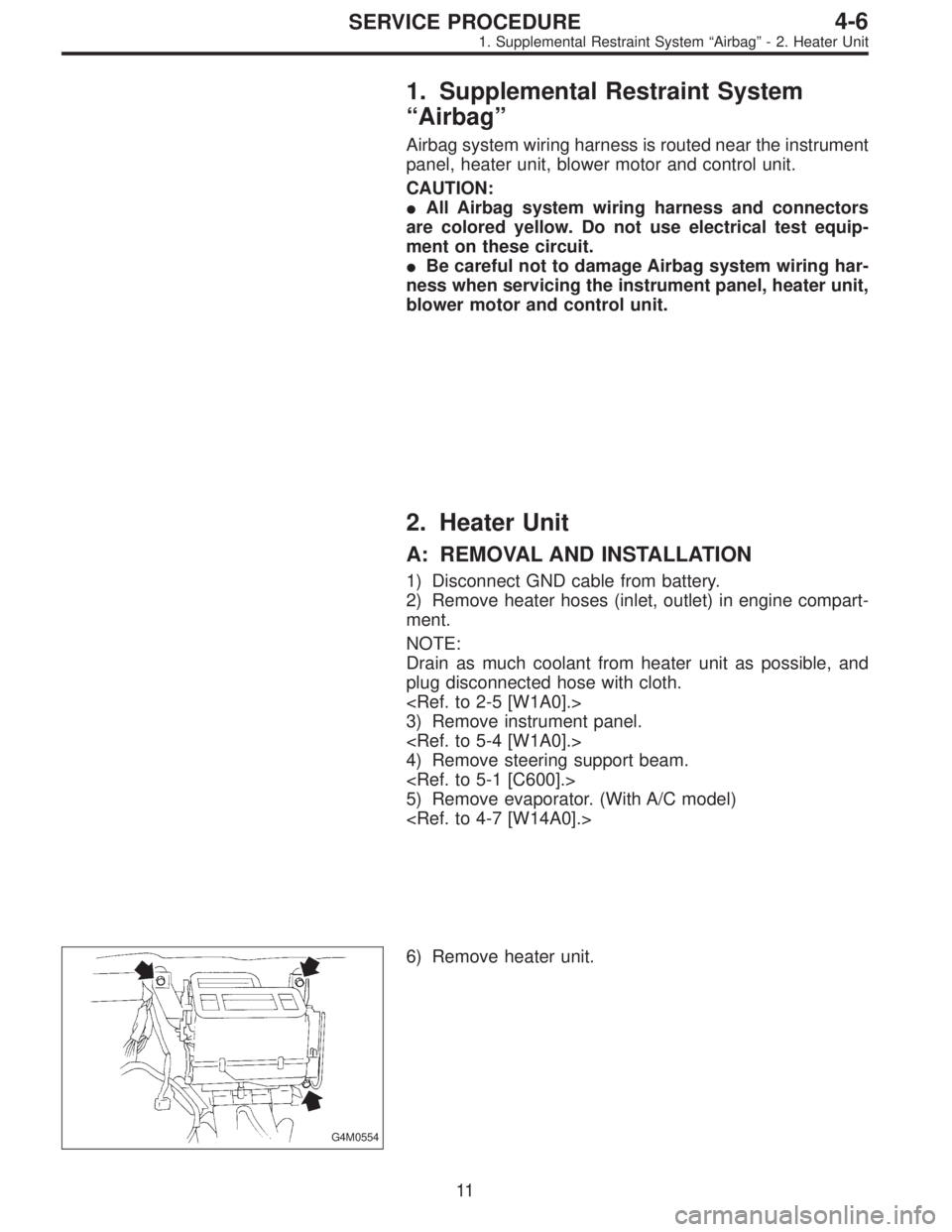
G4M0554
6) Remove heater unit.
11
4-6SERVICE PROCEDURE
1. Supplemental Restraint System“Airbag”- 2. Heater Unit
Page 852 of 2248
1. Supplemental Restraint System
“Airbag”
Airbag system wiring harness is routed near the instrument
panel, heater unit, blower motor and control unit.
CAUTION:
�All Airbag system wiring harness and connectors
are colored yellow. Do not use electrical test equip-
ment on these circuit.
�Be careful not to damage Airbag system wiring har-
ness when servicing the instrument panel, heater unit,
blower motor and control unit.
2. Heater Unit
A: REMOVAL AND INSTALLATION
1) Disconnect GND cable from battery.
2) Remove heater hoses (inlet, outlet) in engine compart-
ment.
NOTE:
Drain as much coolant from heater unit as possible, and
plug disconnected hose with cloth.
3) Remove instrument panel.
4) Remove steering support beam.
5) Remove evaporator. (With A/C model)
G4M0554
6) Remove heater unit.
11
4-6SERVICE PROCEDURE
1. Supplemental Restraint System“Airbag”- 2. Heater Unit
Page 1096 of 2248
, 100 minutes (AT)
Cold cranking ampere 430 amperes (MT), 490 amperes (AT)
Fuse10 A, 15 A, 20 A
Combination
meterSpeedometer")
1. Body Electrical
A: SPECIFICATIONS
BatteryReserve capacity 82 minutes (MT), 100 minutes (AT)
Cold cranking ampere 430 amperes (MT), 490 amperes (AT)
Fuse10 A, 15 A, 20 A
Combination
meterSpeedometer Electric pulse type
Tachometer Electric impulse type
Water temperature gauge Thermistor cross coil type
Fuel gauge Resistance cross coil type
Charge indicator light 12 V—1.4 W
Brake fluid level warning/parking brake indicator light 12 V—1.4 W
AT oil temperature warning light (AWD only) 12 V—1.4 W
A.B.S. warning light 12 V—1.4 W
CHECK ENGINE warning light
(Malfunction indicator lamp)12 V—1.4 W
Oil pressure warning light 12 V—1.4 W
AIRBAG system warning light 12 V—1.4 W
Low fuel warning light 12 V—3W
FWD indicator light 12 V—1.4 W
TCS warning light 12 V—1.4 W
TCS indicator light 12 V—1.4 W
Turn signal indicator light 12 V—1.4 W (2 pieces)
Seat belt warning light 12 V—1.4 W
Door open warning light 12 V—1.4 W
Headlight beam indicator light 12 V—1.4 W
Meter illumination light12 V—3 W (2 pieces)
12 V—3.4 W (4 pieces)
Headlight 12 V—60/55 W (Halogen)
Front clearance light 12 V—5W
Turn signal lightFront 12 V—21 W
Rear 12 V—21 W
Tail/Stop light 12 V—5/21 W
Back-up light 12 V—21 W
High-mount stop light12 V—18 W (SEDAN), 12 V—13 W
(WAGON)
License plate light 12 V—5W
Room light 12 V—8W
Trunk room light (SEDAN) 12 V—5W
Luggage room light (WAGON) 12 V—5W
Spot light 12 V—8 W (2 pieces)
Glove box light 12 V—3.4 W
Ash tray illumination light 12 V—1.7 W
Selector lever illumination light (AT model) 12 V—1.7 W
2
6-2SPECIFICATIONS
1. Body Electrical
Page 1187 of 2248
6. Security System
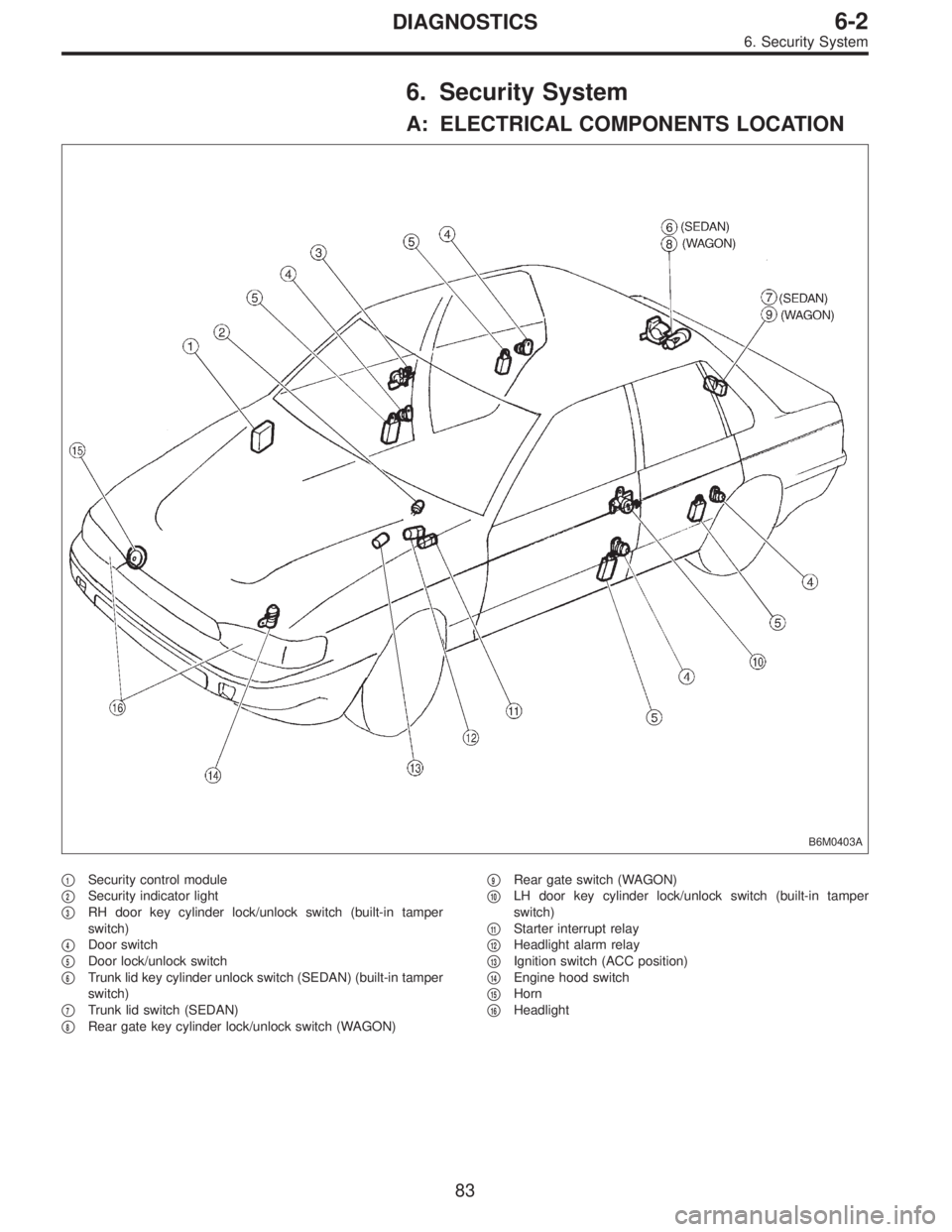
A: ELECTRICAL COMPONENTS LOCATION
B6M0403A
�1Security control module
�
2Security indicator light
�
3RH door key cylinder lock/unlock switch (built-in tamper
switch)
�
4Door switch
�
5Door lock/unlock switch
�
6Trunk lid key cylinder unlock switch (SEDAN) (built-in tamper
switch)
�
7Trunk lid switch (SEDAN)
�
8Rear gate key cylinder lock/unlock switch (WAGON)�
9Rear gate switch (WAGON)
�
10LH door key cylinder lock/unlock switch (built-in tamper
switch)
�
11Starter interrupt relay
�
12Headlight alarm relay
�
13Ignition switch (ACC position)
�
14Engine hood switch
�
15Horn
�
16Headlight
83
6-2DIAGNOSTICS
6. Security System
Page 1214 of 2248
2. Electrical Components Location
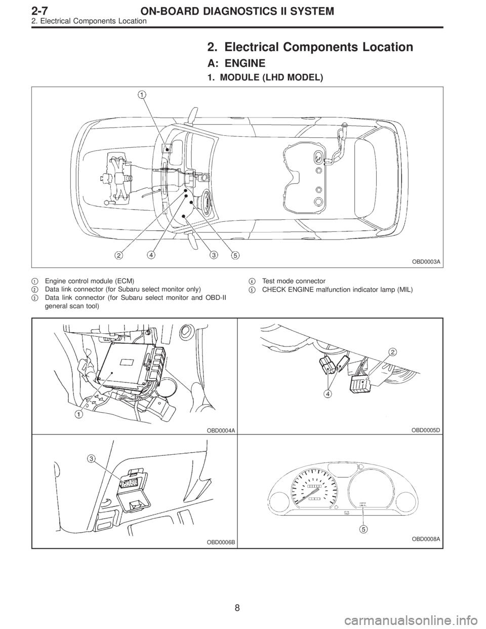
A: ENGINE
1. MODULE (LHD MODEL)
OBD0003A
�1Engine control module (ECM)
�
2Data link connector (for Subaru select monitor only)
�
3Data link connector (for Subaru select monitor and OBD-II
general scan tool)�
4Test mode connector
�
5CHECK ENGINE malfunction indicator lamp (MIL)
OBD0004AOBD0005D
OBD0006BOBD0008A
8
2-7ON-BOARD DIAGNOSTICS II SYSTEM
2. Electrical Components Location
Page 1215 of 2248
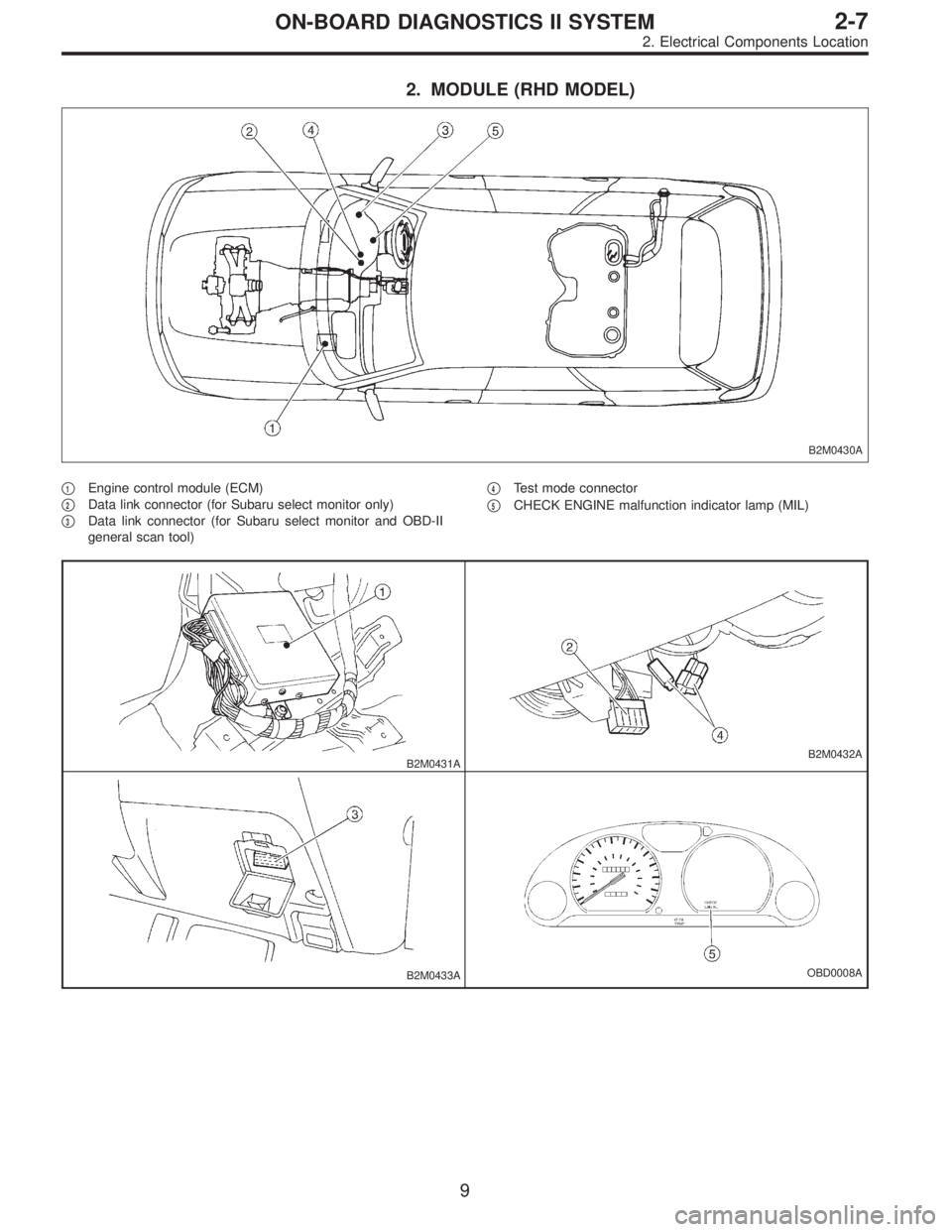
2. MODULE (RHD MODEL)
B2M0430A
�1Engine control module (ECM)
�
2Data link connector (for Subaru select monitor only)
�
3Data link connector (for Subaru select monitor and OBD-II
general scan tool)�
4Test mode connector
�
5CHECK ENGINE malfunction indicator lamp (MIL)
B2M0431AB2M0432A
B2M0433AOBD0008A
9
2-7ON-BOARD DIAGNOSTICS II SYSTEM
2. Electrical Components Location
Page 1216 of 2248
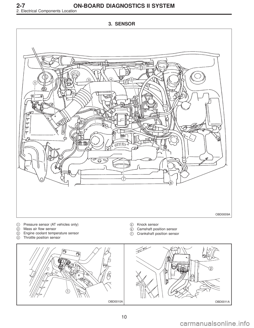
3. SENSOR
OBD0009A
�1Pressure sensor (AT vehicles only)
�
2Mass air flow sensor
�
3Engine coolant temperature sensor
�
4Throttle position sensor�
5Knock sensor
�
6Camshaft position sensor
�
7Crankshaft position sensor
OBD0010AOBD0011A
10
2-7ON-BOARD DIAGNOSTICS II SYSTEM
2. Electrical Components Location