Page 1271 of 2248

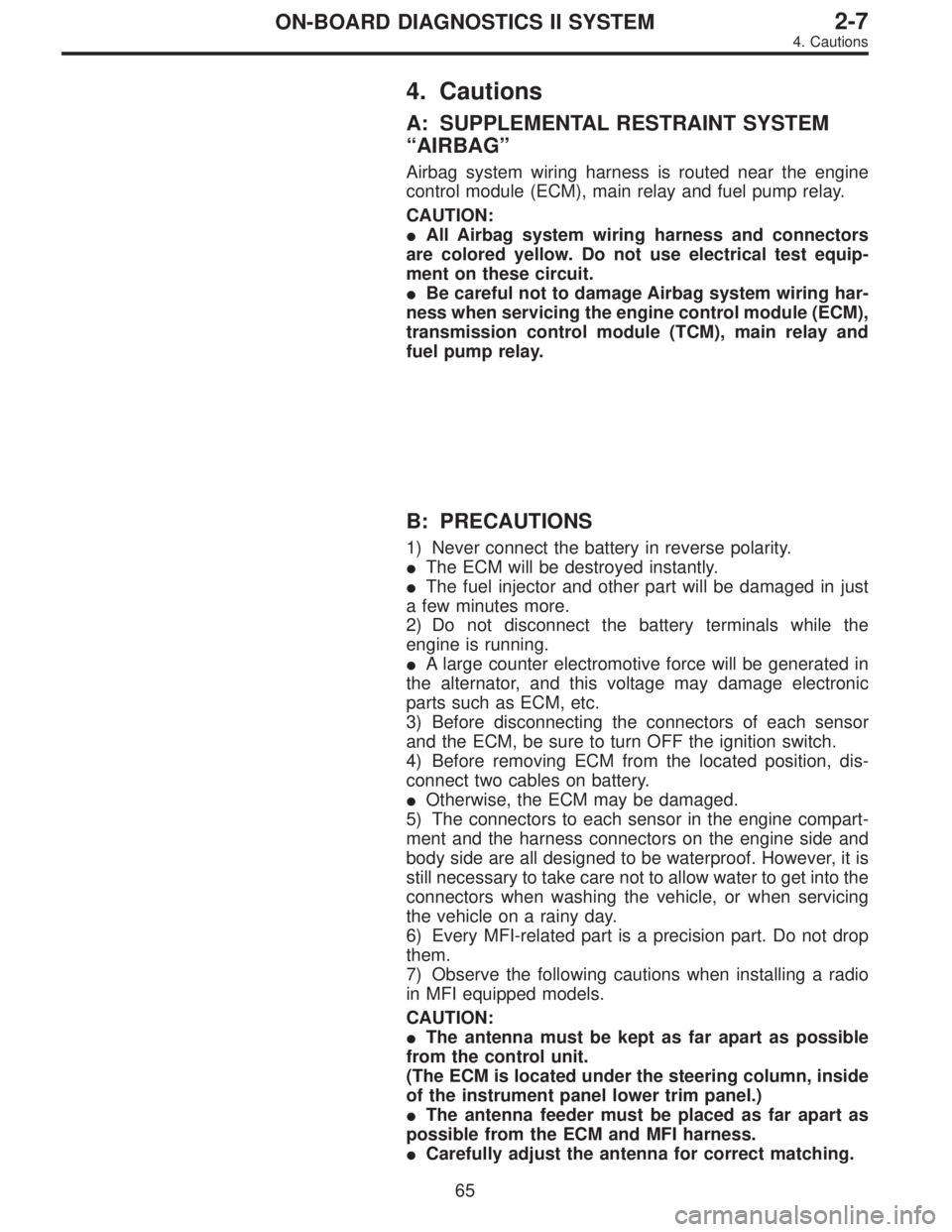
4. Cautions
A: SUPPLEMENTAL RESTRAINT SYSTEM
“AIRBAG”
Airbag system wiring harness is routed near the engine
control module (ECM), main relay and fuel pump relay.
CAUTION:
�All Airbag system wiring harness and connectors
are colored yellow. Do not use electrical test equip-
ment on these circuit.
�Be careful not to damage Airbag system wiring har-
ness when servicing the engine control module (ECM),
transmission control module (TCM), main relay and
fuel pump relay.
B: PRECAUTIONS
1) Never connect the battery in reverse polarity.
�The ECM will be destroyed instantly.
�The fuel injector and other part will be damaged in just
a few minutes more.
2) Do not disconnect the battery terminals while the
engine is running.
�A large counter electromotive force will be generated in
the alternator, and this voltage may damage electronic
parts such as ECM, etc.
3) Before disconnecting the connectors of each sensor
and the ECM, be sure to turn OFF the ignition switch.
4) Before removing ECM from the located position, dis-
connect two cables on battery.
�Otherwise, the ECM may be damaged.
5) The connectors to each sensor in the engine compart-
ment and the harness connectors on the engine side and
body side are all designed to be waterproof. However, it is
still necessary to take care not to allow water to get into the
connectors when washing the vehicle, or when servicing
the vehicle on a rainy day.
6) Every MFI-related part is a precision part. Do not drop
them.
7) Observe the following cautions when installing a radio
in MFI equipped models.
CAUTION:
�The antenna must be kept as far apart as possible
from the control unit.
(The ECM is located under the steering column, inside
of the instrument panel lower trim panel.)
�The antenna feeder must be placed as far apart as
possible from the ECM and MFI harness.
�Carefully adjust the antenna for correct matching.
65
2-7ON-BOARD DIAGNOSTICS II SYSTEM
4. Cautions
Page 1279 of 2248
6. Wiring Diagram and Wiring Harness
A: WIRING DIAGRAM
1. ENGINE ELECTRICAL SYSTEM
�LHD model
BU10-02A
73
2-7ON-BOARD DIAGNOSTICS II SYSTEM
6. Wiring Diagram and Wiring Harness
Page 1283 of 2248
1. ENGINE ELECTRICAL SYSTEM
�RHD model
BUR10-01A
77
2-7ON-BOARD DIAGNOSTICS II SYSTEM
6. Wiring Diagram and Wiring Harness
Page 1291 of 2248
B: ELECTRICAL WIRING HARNESS AND
GROUND POINT
B6M0267A
�1Front wiring harness
�
2Engine wiring harness
�
3Room light cord
�
4Bulkhead wiring harness
�
5Instrument panel wiring harness
�
6Front door cord RH
�
7Rear door cord RH
�
8Rear wiring harness
�
9Trunk lid cord (Sedan)�
10Rear defogger ground cord (Sedan)
�
11Fuel tank cord
�
12Rear door cord LH
�
13Front door cord LH
�
14Sunroof cord
�
15Floor wiring harness
�
16Transmission cord
�
17Rear gate cord (Wagon)
�
18Rear oxygen sensor cord
85
2-7ON-BOARD DIAGNOSTICS II SYSTEM
6. Wiring Diagram and Wiring Harness
Page 1340 of 2248

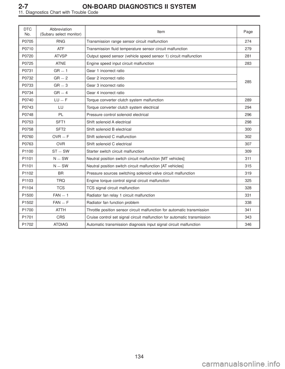
DTC
No.Abbreviation
(Subaru select monitor)Item Page
P0705 RNG Transmission range sensor circuit malfunction 274
P0710 ATF Transmission fluid temperature sensor circuit malfunction 279
P0720 ATVSP Output speed sensor (vehicle speed sensor 1) circuit malfunction 281
P0725 ATNE Engine speed input circuit malfunction 283
P0731 GR
—1 Gear 1 incorrect ratio
285 P0732 GR
—2 Gear 2 incorrect ratio
P0733 GR
—3 Gear 3 incorrect ratio
P0734 GR
—4 Gear 4 incorrect ratio
P0740 LU
—F Torque converter clutch system malfunction 289
P0743 LU Torque converter clutch system electrical 294
P0748 PL Pressure control solenoid electrical 296
P0753 SFT1 Shift solenoid A electrical 298
P0758 SFT2 Shift solenoid B electrical 300
P0760 OVR
—F Shift solenoid C malfunction 302
P0763 OVR Shift solenoid C electrical 307
P1100 ST
—SW Starter switch circuit malfunction 309
P1101 N
—SW Neutral position switch circuit malfunction [MT vehicles] 311
P1101 N
—SW Neutral position switch circuit malfunction [AT vehicles] 315
P1102 BR Pressure sources switching solenoid valve circuit malfunction 319
P1103 TRQ Engine torque control signal circuit malfunction 325
P1104 TCS TCS signal circuit malfunction 328
P1500 FAN
—1 Radiator fan relay 1 circuit malfunction 331
P1502 FAN
—F Radiator fan function problem 338
P1700 ATTH Throttle position sensor circuit malfunction for automatic transmission 341
P1701 CRS Cruise control set signal circuit malfunction for automatic transmission 343
P1702 ATDIAG Automatic transmission diagnosis input signal circuit malfunction 346
134
2-7ON-BOARD DIAGNOSTICS II SYSTEM
11. Diagnostics Chart with Trouble Code
Page 1439 of 2248

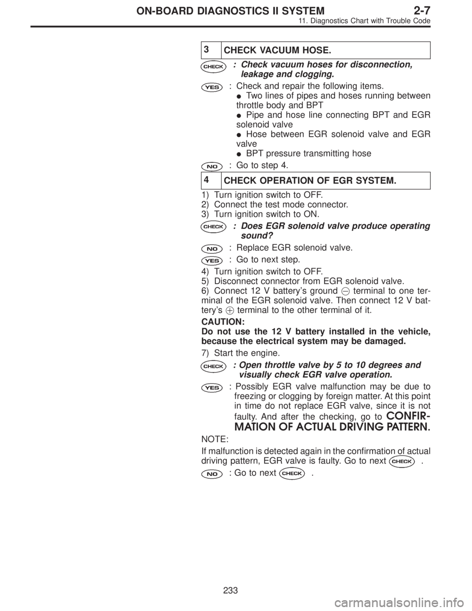
3
CHECK VACUUM HOSE.
: Check vacuum hoses for disconnection,
leakage and clogging.
: Check and repair the following items.
�Two lines of pipes and hoses running between
throttle body and BPT
�Pipe and hose line connecting BPT and EGR
solenoid valve
�Hose between EGR solenoid valve and EGR
valve
�BPT pressure transmitting hose
: Go to step 4.
4
CHECK OPERATION OF EGR SYSTEM.
1) Turn ignition switch to OFF.
2) Connect the test mode connector.
3) Turn ignition switch to ON.
: Does EGR solenoid valve produce operating
sound?
: Replace EGR solenoid valve.
: Go to next step.
4) Turn ignition switch to OFF.
5) Disconnect connector from EGR solenoid valve.
6) Connect 12 V battery’s ground�terminal to one ter-
minal of the EGR solenoid valve. Then connect 12 V bat-
tery’s�terminal to the other terminal of it.
CAUTION:
Do not use the 12 V battery installed in the vehicle,
because the electrical system may be damaged.
7) Start the engine.
: Open throttle valve by 5 to 10 degrees and
visually check EGR valve operation.
: Possibly EGR valve malfunction may be due to
freezing or clogging by foreign matter. At this point
in time do not replace EGR valve, since it is not
faulty. And after the checking, go to
CONFIR-
MATION OF ACTUAL DRIVING PATTERN.
NOTE:
If malfunction is detected again in the confirmation of actual
driving pattern, EGR valve is faulty. Go to next
.
: Go to next.
233
2-7ON-BOARD DIAGNOSTICS II SYSTEM
11. Diagnostics Chart with Trouble Code
Page 1480 of 2248

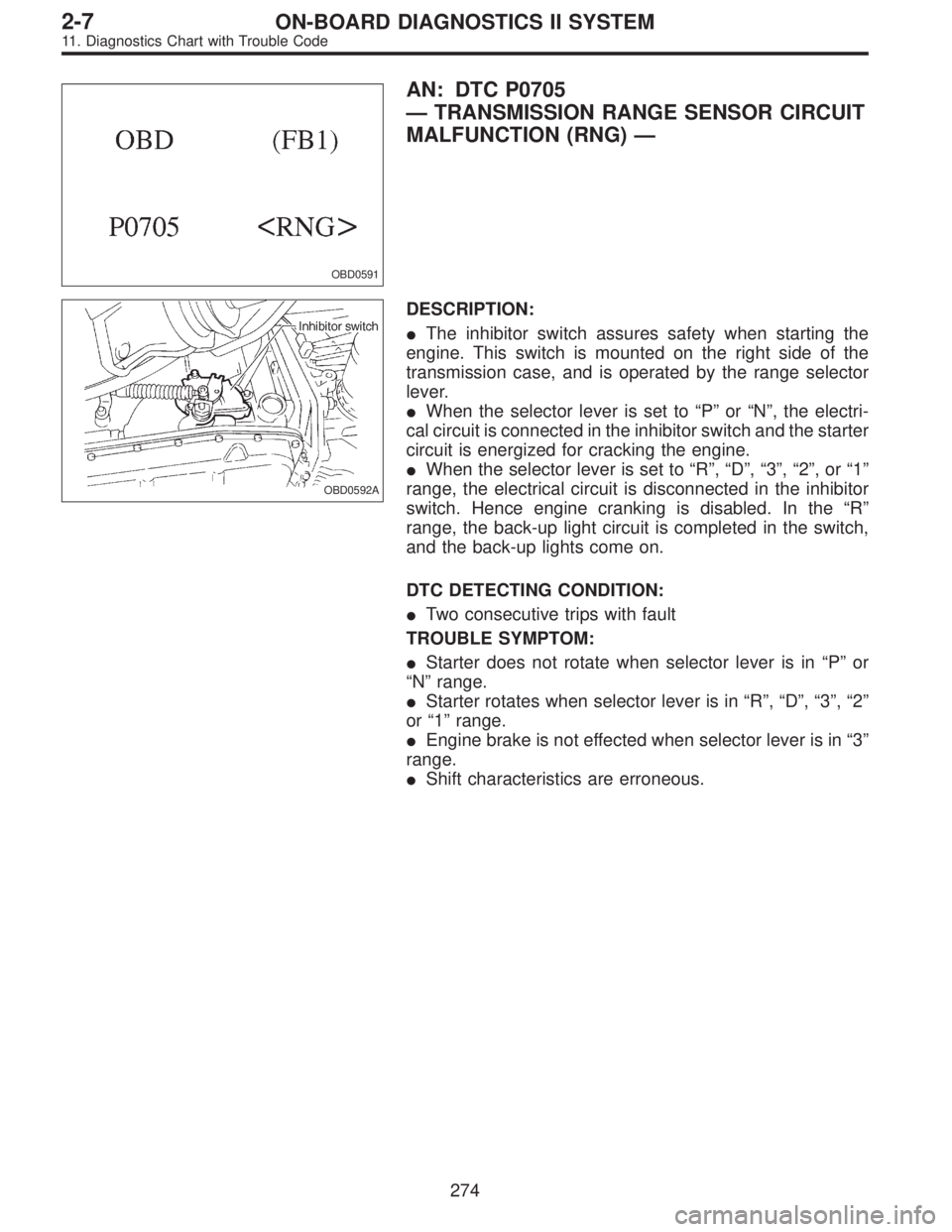
OBD0591
AN: DTC P0705
—TRANSMISSION RANGE SENSOR CIRCUIT
MALFUNCTION (RNG)—
OBD0592A
DESCRIPTION:
�The inhibitor switch assures safety when starting the
engine. This switch is mounted on the right side of the
transmission case, and is operated by the range selector
lever.
�When the selector lever is set to“P”or“N”, the electri-
cal circuit is connected in the inhibitor switch and the starter
circuit is energized for cracking the engine.
�When the selector lever is set to“R”,“D”,“3”,“2”,or“1”
range, the electrical circuit is disconnected in the inhibitor
switch. Hence engine cranking is disabled. In the“R”
range, the back-up light circuit is completed in the switch,
and the back-up lights come on.
DTC DETECTING CONDITION:
�Two consecutive trips with fault
TROUBLE SYMPTOM:
�Starter does not rotate when selector lever is in“P”or
“N”range.
�Starter rotates when selector lever is in“R”,“D”,“3”,“2”
or“1”range.
�Engine brake is not effected when selector lever is in“3”
range.
�Shift characteristics are erroneous.
274
2-7ON-BOARD DIAGNOSTICS II SYSTEM
11. Diagnostics Chart with Trouble Code
Page 1485 of 2248
OBD0380
AO: DTC P0710
—TRANSMISSION FLUID TEMPERATURE
SENSOR CIRCUIT MALFUNCTION (ATF)—
H2M1145
DESCRIPTION:
This sensor is mounted to the control valve in the transmis-
sion. It detects temperature change as an analog electrical
signal. The output characteristics of the sensor are shown
in the illustration.
DTC DETECTING CONDITION:
�Two consecutive trips with fault
TROUBLE SYMPTOM:
�No shift up to 4th speed (after engine warm-up)
�No lock-up occurs. (after engine warm-up)
�Excessive shift shock
279
2-7ON-BOARD DIAGNOSTICS II SYSTEM
11. Diagnostics Chart with Trouble Code