Page 153 of 2248
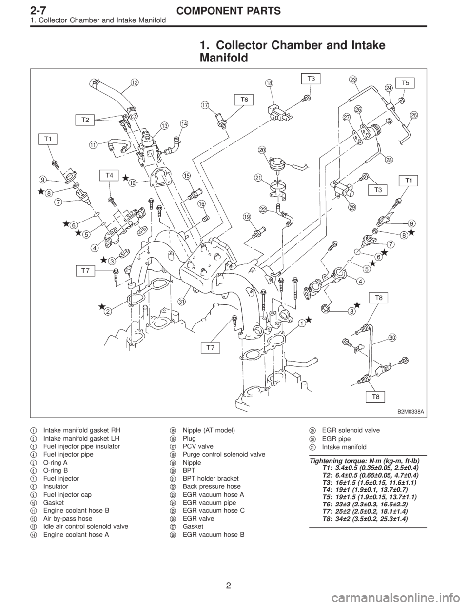
1. Collector Chamber and Intake
Manifold
B2M0338A
�1Intake manifold gasket RH
�
2Intake manifold gasket LH
�
3Fuel injector pipe insulator
�
4Fuel injector pipe
�
5O-ring A
�
6O-ring B
�
7Fuel injector
�
8Insulator
�
9Fuel injector cap
�
10Gasket
�
11Engine coolant hose B
�
12Air by-pass hose
�
13Idle air control solenoid valve
�
14Engine coolant hose A�
15Nipple (AT model)
�
16Plug
�
17PCV valve
�
18Purge control solenoid valve
�
19Nipple
�
20BPT
�
21BPT holder bracket
�
22Back pressure hose
�
23EGR vacuum hose A
�
24EGR vacuum pipe
�
25EGR vacuum hose C
�
26EGR valve
�
27Gasket
�
28EGR vacuum hose B�
29EGR solenoid valve
�
30EGR pipe
�
31Intake manifold
Tightening torque: N⋅m (kg-m, ft-lb)
T1: 3.4±0.5 (0.35±0.05, 2.5±0.4)
T2: 6.4±0.5 (0.65±0.05, 4.7±0.4)
T3: 16±1.5 (1.6±0.15, 11.6±1.1)
T4: 19±1 (1.9±0.1, 13.7±0.7)
T5: 19±1.5 (1.9±0.15, 13.7±1.1)
T6: 23±3 (2.3±0.3, 16.6±2.2)
T7: 25±2 (2.5±0.2, 18.1±1.4)
T8: 34±2 (3.5±0.2, 25.3±1.4)
2
2-7COMPONENT PARTS
1. Collector Chamber and Intake Manifold
Page 160 of 2248
B2M0334
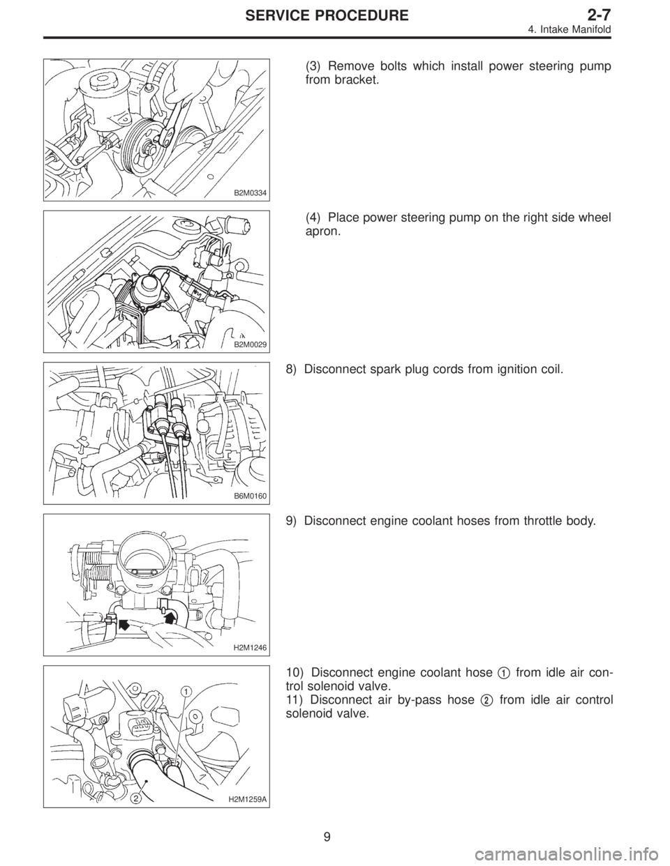
(3) Remove bolts which install power steering pump
from bracket.
B2M0029
(4) Place power steering pump on the right side wheel
apron.
B6M0160
8) Disconnect spark plug cords from ignition coil.
H2M1246
9) Disconnect engine coolant hoses from throttle body.
H2M1259A
10) Disconnect engine coolant hose�1from idle air con-
trol solenoid valve.
11) Disconnect air by-pass hose�
2from idle air control
solenoid valve.
9
2-7SERVICE PROCEDURE
4. Intake Manifold
Page 163 of 2248
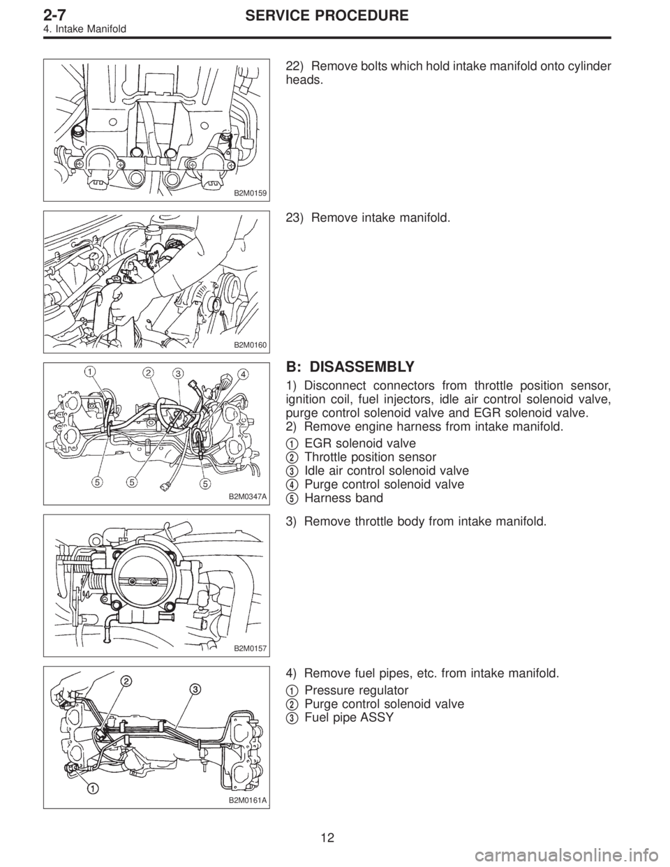
B2M0159
22) Remove bolts which hold intake manifold onto cylinder
heads.
B2M0160
23) Remove intake manifold.
B2M0347A
B: DISASSEMBLY
1) Disconnect connectors from throttle position sensor,
ignition coil, fuel injectors, idle air control solenoid valve,
purge control solenoid valve and EGR solenoid valve.
2) Remove engine harness from intake manifold.
�
1EGR solenoid valve
�
2Throttle position sensor
�
3Idle air control solenoid valve
�
4Purge control solenoid valve
�
5Harness band
B2M0157
3) Remove throttle body from intake manifold.
B2M0161A
4) Remove fuel pipes, etc. from intake manifold.
�
1Pressure regulator
�
2Purge control solenoid valve
�
3Fuel pipe ASSY
12
2-7SERVICE PROCEDURE
4. Intake Manifold
Page 164 of 2248
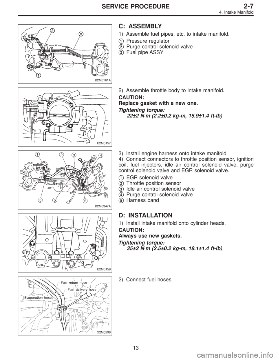
B2M0161A
C: ASSEMBLY
1) Assemble fuel pipes, etc. to intake manifold.
�
1Pressure regulator
�
2Purge control solenoid valve
�
3Fuel pipe ASSY
B2M0157
2) Assemble throttle body to intake manifold.
CAUTION:
Replace gasket with a new one.
Tightening torque:
22±2 N⋅m (2.2±0.2 kg-m, 15.9±1.4 ft-lb)
B2M0347A
3) Install engine harness onto intake manifold.
4) Connect connectors to throttle position sensor, ignition
coil, fuel injectors, idle air control solenoid valve, purge
control solenoid valve and EGR solenoid valve.
�
1EGR solenoid valve
�
2Throttle position sensor
�
3Idle air control solenoid valve
�
4Purge control solenoid valve
�
5Harness band
B2M0159
D: INSTALLATION
1) Install intake manifold onto cylinder heads.
CAUTION:
Always use new gaskets.
Tightening torque:
25±2 N⋅m (2.5±0.2 kg-m, 18.1±1.4 ft-lb)
G2M0296
2) Connect fuel hoses.
13
2-7SERVICE PROCEDURE
4. Intake Manifold
Page 166 of 2248
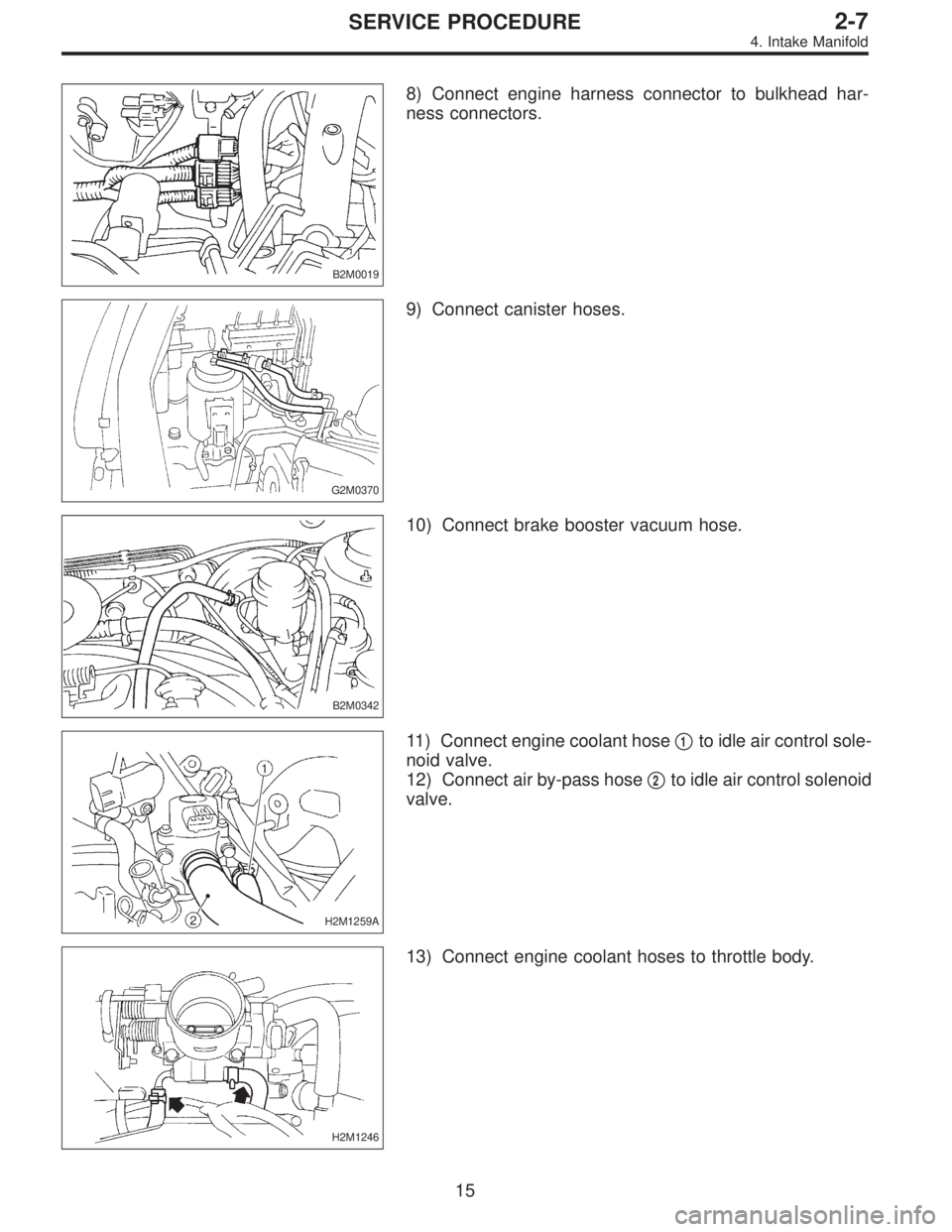
B2M0019
8) Connect engine harness connector to bulkhead har-
ness connectors.
G2M0370
9) Connect canister hoses.
B2M0342
10) Connect brake booster vacuum hose.
H2M1259A
11) Connect engine coolant hose�1to idle air control sole-
noid valve.
12) Connect air by-pass hose�
2to idle air control solenoid
valve.
H2M1246
13) Connect engine coolant hoses to throttle body.
15
2-7SERVICE PROCEDURE
4. Intake Manifold
Page 177 of 2248
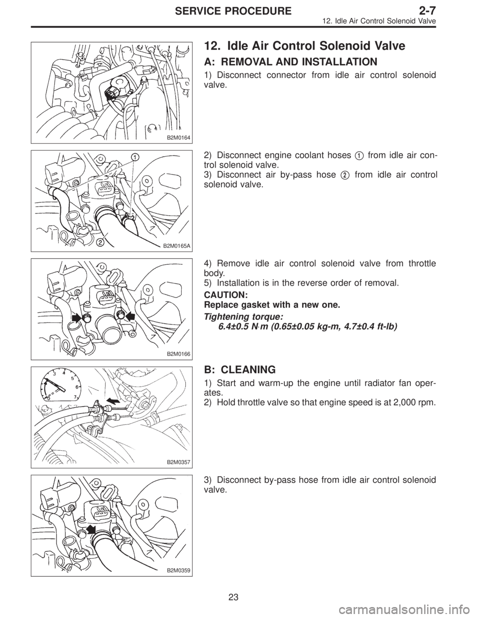
B2M0164
12. Idle Air Control Solenoid Valve
A: REMOVAL AND INSTALLATION
1) Disconnect connector from idle air control solenoid
valve.
B2M0165A
2) Disconnect engine coolant hoses�1from idle air con-
trol solenoid valve.
3) Disconnect air by-pass hose�
2from idle air control
solenoid valve.
B2M0166
4) Remove idle air control solenoid valve from throttle
body.
5) Installation is in the reverse order of removal.
CAUTION:
Replace gasket with a new one.
Tightening torque:
6.4±0.5 N⋅m (0.65±0.05 kg-m, 4.7±0.4 ft-lb)
B2M0357
B: CLEANING
1) Start and warm-up the engine until radiator fan oper-
ates.
2) Hold throttle valve so that engine speed is at 2,000 rpm.
B2M0359
3) Disconnect by-pass hose from idle air control solenoid
valve.
23
2-7SERVICE PROCEDURE
12. Idle Air Control Solenoid Valve
Page 178 of 2248
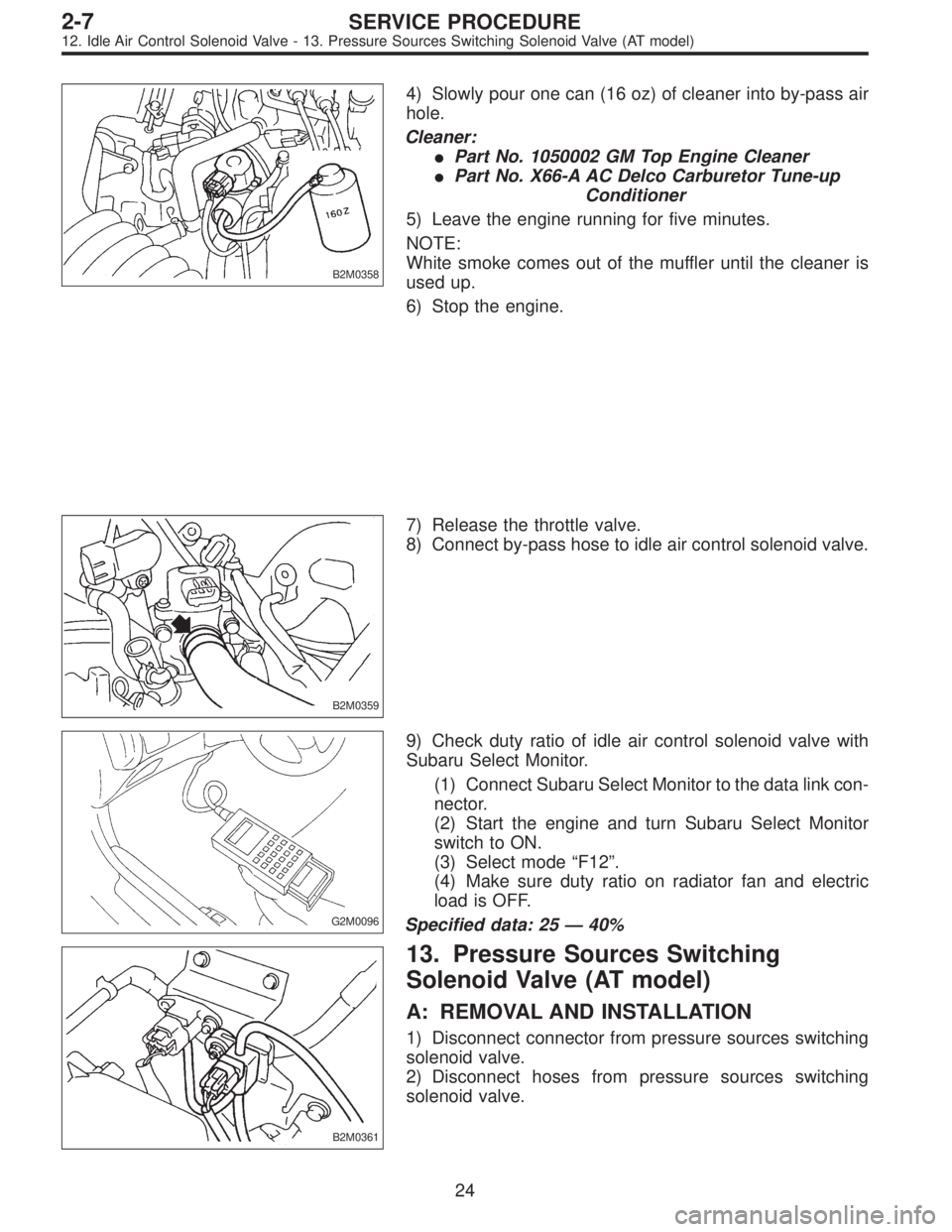
B2M0358
4) Slowly pour one can (16 oz) of cleaner into by-pass air
hole.
Cleaner:
�Part No. 1050002 GM Top Engine Cleaner
�Part No. X66-A AC Delco Carburetor Tune-up
Conditioner
5) Leave the engine running for five minutes.
NOTE:
White smoke comes out of the muffler until the cleaner is
used up.
6) Stop the engine.
B2M0359
7) Release the throttle valve.
8) Connect by-pass hose to idle air control solenoid valve.
G2M0096
9) Check duty ratio of idle air control solenoid valve with
Subaru Select Monitor.
(1) Connect Subaru Select Monitor to the data link con-
nector.
(2) Start the engine and turn Subaru Select Monitor
switch to ON.
(3) Select mode“F12”.
(4) Make sure duty ratio on radiator fan and electric
load is OFF.
Specified data: 25—40%
B2M0361
13. Pressure Sources Switching
Solenoid Valve (AT model)
A: REMOVAL AND INSTALLATION
1) Disconnect connector from pressure sources switching
solenoid valve.
2) Disconnect hoses from pressure sources switching
solenoid valve.
24
2-7SERVICE PROCEDURE
12. Idle Air Control Solenoid Valve - 13. Pressure Sources Switching Solenoid Valve (AT model)
Page 179 of 2248

B2M0358
4) Slowly pour one can (16 oz) of cleaner into by-pass air
hole.
Cleaner:
�Part No. 1050002 GM Top Engine Cleaner
�Part No. X66-A AC Delco Carburetor Tune-up
Conditioner
5) Leave the engine running for five minutes.
NOTE:
White smoke comes out of the muffler until the cleaner is
used up.
6) Stop the engine.
B2M0359
7) Release the throttle valve.
8) Connect by-pass hose to idle air control solenoid valve.
G2M0096
9) Check duty ratio of idle air control solenoid valve with
Subaru Select Monitor.
(1) Connect Subaru Select Monitor to the data link con-
nector.
(2) Start the engine and turn Subaru Select Monitor
switch to ON.
(3) Select mode“F12”.
(4) Make sure duty ratio on radiator fan and electric
load is OFF.
Specified data: 25—40%
B2M0361
13. Pressure Sources Switching
Solenoid Valve (AT model)
A: REMOVAL AND INSTALLATION
1) Disconnect connector from pressure sources switching
solenoid valve.
2) Disconnect hoses from pressure sources switching
solenoid valve.
24
2-7SERVICE PROCEDURE
12. Idle Air Control Solenoid Valve - 13. Pressure Sources Switching Solenoid Valve (AT model)