Page 27 of 2248
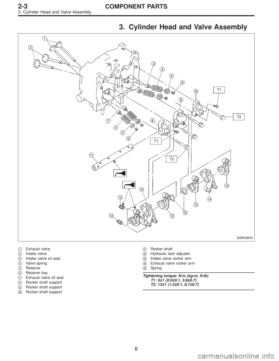
3. Cylinder Head and Valve Assembly
B2M0380A
�1Exhaust valve
�
2Intake valve
�
3Intake valve oil seal
�
4Valve spring
�
5Retainer
�
6Retainer key
�
7Exhaust valve oil seal
�
8Rocker shaft support
�
9Rocker shaft support
�
10Rocker shaft support�
11Rocker shaft
�
12Hydraulic lash adjuster
�
13Intake valve rocker arm
�
14Exhaust valve rocker arm
�
15Spring
Tightening torque: N⋅m (kg-m, ft-lb)
T1: 5±1 (0.5±0.1, 3.6±0.7)
T2: 12±1 (1.2±0.1, 8.7±0.7)
8
2-3COMPONENT PARTS
3. Cylinder Head and Valve Assembly
Page 29 of 2248
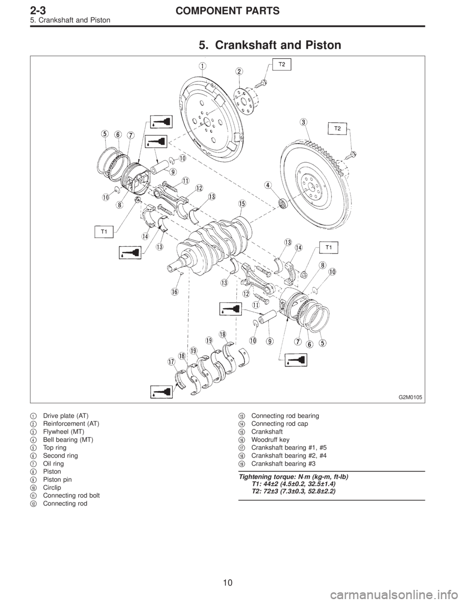
5. Crankshaft and Piston
G2M0105
�1Drive plate (AT)
�
2Reinforcement (AT)
�
3Flywheel (MT)
�
4Bell bearing (MT)
�
5Top ring
�
6Second ring
�
7Oil ring
�
8Piston
�
9Piston pin
�
10Circlip
�
11Connecting rod bolt
�
12Connecting rod�
13Connecting rod bearing
�
14Connecting rod cap
�
15Crankshaft
�
16Woodruff key
�
17Crankshaft bearing #1, #5
�
18Crankshaft bearing #2, #4
�
19Crankshaft bearing #3
Tightening torque: N⋅m (kg-m, ft-lb)
T1: 44±2 (4.5±0.2, 32.5±1.4)
T2: 72±3 (7.3±0.3, 52.8±2.2)
10
2-3COMPONENT PARTS
5. Crankshaft and Piston
Page 41 of 2248
B2M0108A
3) Measure the extension of rod beyond the body. If it is
not within specifications, replace with a new one.
Rod extension: H
15.4—16.4 mm (0.606—0.646 in)
3. BELT TENSIONER
1) Check mating surfaces of timing belt and contact point
of tension adjuster rod for abnormal wear or scratches.
Replace belt tensioner if faulty.
2) Check spacer and tensioner bushing for wear.
3) Check tensioner for smooth rotation. Replace if noise or
excessive play is noted.
4) Check tensioner for grease leakage.
4. BELT IDLER
1) Check idler for smooth rotation. Replace if noise or
excessive play is noted.
2) Check outer contacting surfaces of idler pulley for
abnormal wear and scratches.
3) Check idler for grease leakage.
5. SPROCKET
1) Check sprocket teeth for abnormal wear and scratches.
2) Make sure there is no free play between sprocket and
key.
3) Check crankshaft sprocket notch for sensor for damage
and contamination of foreign matter.
21
2-3SERVICE PROCEDURE
3. Timing Belt
Page 61 of 2248
B: DISASSEMBLY
B2M0121A
1) Remove rocker cover.
2) Remove valve rocker assembly.
3) Remove camshaft and support.
4) Place cylinder head on ST.
ST 498267200 CYLINDER HEAD TABLE
B2M0386A
5) Set ST on valve spring. Compress valve spring and
remove the valve spring retainer key. Remove each valve
and valve spring.
ST 499718000 VALVE SPRING REMOVER
CAUTION:
�Mark each valve to prevent confusion.
�Use extreme care not to damage the lips of the
intake valve oil seals and exhaust valve oil seals.
6) Removal of plug (cylinder head LH)
CAUTION:
Do not remove plug unless necessary.
40
2-3SERVICE PROCEDURE
6. Cylinder Head
Page 68 of 2248
B2M0386A
(3) Install valve spring and retainer.
CAUTION:
Be sure to install the valve springs with their close-
coiled end facing the seat on the cylinder head.
(4) Set ST on valve spring.
ST 499718000 VALVE SPRING REMOVER
(5) Compress valve spring and fit valve spring retainer
key.
(6) After installing, tap valve spring retainers lightly
with wooden hammer for better seating.
3) Install camshaft and support.
4) Install valve rocker assembly.
5) Install rocker cover.
47
2-3SERVICE PROCEDURE
6. Cylinder Head
Page 285 of 2248
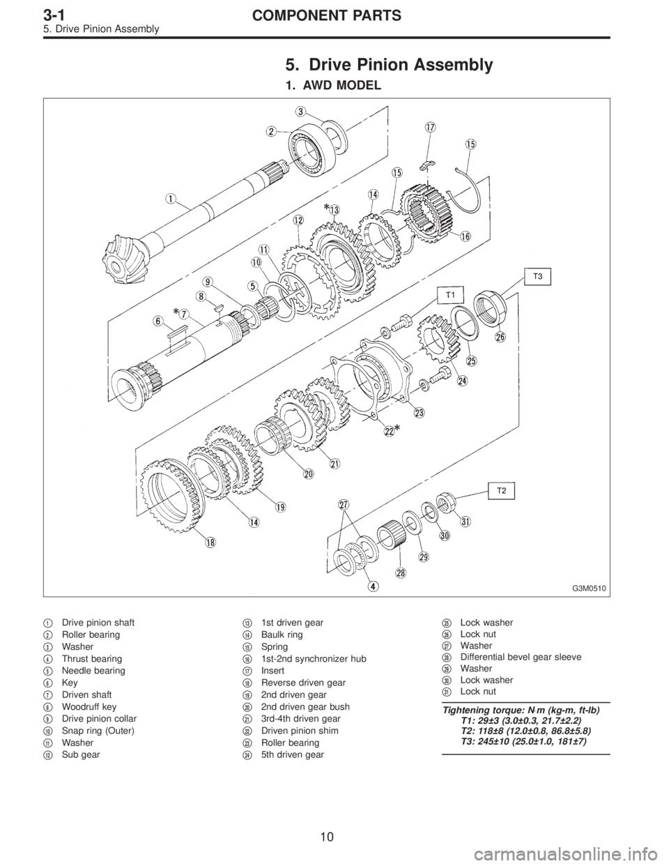
5. Drive Pinion Assembly
1. AWD MODEL
G3M0510
�1Drive pinion shaft
�
2Roller bearing
�
3Washer
�
4Thrust bearing
�
5Needle bearing
�
6Key
�
7Driven shaft
�
8Woodruff key
�
9Drive pinion collar
�
10Snap ring (Outer)
�
11Washer
�
12Sub gear�
131st driven gear
�
14Baulk ring
�
15Spring
�
161st-2nd synchronizer hub
�
17Insert
�
18Reverse driven gear
�
192nd driven gear
�
202nd driven gear bush
�
213rd-4th driven gear
�
22Driven pinion shim
�
23Roller bearing
�
245th driven gear�
25Lock washer
�
26Lock nut
�
27Washer
�
28Differential bevel gear sleeve
�
29Washer
�
30Lock washer
�
31Lock nut
Tightening torque: N⋅m (kg-m, ft-lb)
T1: 29±3 (3.0±0.3, 21.7±2.2)
T2: 118±8 (12.0±0.8, 86.8±5.8)
T3: 245±10 (25.0±1.0, 181±7)
10
3-1COMPONENT PARTS
5. Drive Pinion Assembly
Page 286 of 2248
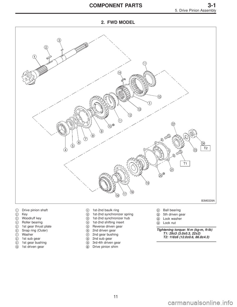
2. FWD MODEL
B3M0339A
�1Drive pinion shaft
�
2Key
�
3Woodruff key
�
4Roller bearing
�
51st gear thrust plate
�
6Snap ring (Outer)
�
7Washer
�
81st sub gear
�
91st gear bushing
�
101st driven gear�
111st-2nd baulk ring
�
121st-2nd synchronizer spring
�
131st-2nd synchronizer hub
�
141st-2nd shifting insert
�
15Reverse driven gear
�
162nd driven gear
�
172nd gear bushing
�
182nd sub gear
�
193rd-4th driven gear
�
20Drive pinion shim�
21Ball bearing
�
225th driven gear
�
23Lock washer
�
24Lock nut
Tightening torque: N⋅m (kg-m, ft-lb)
T1: 29±3 (3.0±0.3, 22±2)
T2: 118±6 (12.0±0.6, 86.8±4.3)
11
3-1COMPONENT PARTS
5. Drive Pinion Assembly
Page 326 of 2248
 Remove woodruff key.
4) Remove roller bearing (42 x 74 x 40), 3rd and 4th driven
gear using ST1 and ST2.
ST1 499757002 SNAP RING PRESS
ST2 899714110 REMOVER
G3M0611
5) Remove the key.
6) Re")
G3M0610
3) Remove woodruff key.
4) Remove roller bearing (42 x 74 x 40), 3rd and 4th driven
gear using ST1 and ST2.
ST1 499757002 SNAP RING PRESS
ST2 899714110 REMOVER
G3M0611
5) Remove the key.
6) Remove 2nd driven gear assembly.
7) Remove 1st driven gear, 2nd gear bushing, gear and
hub using ST1 and ST2.
Replace gear and hub if necessary. Do not attempt to dis-
assemble if at all possible because they must engage at a
specified point. If they have to be disassembled, mark the
engaging point beforehand.
ST1 499757002 SNAP RING PRESS
ST2 899714110 REMOVER
8) Remove sub gears for 1st and 2nd driven gear.
B3M0077A
B: ASSEMBLY
1. GEAR AND HUB ASSEMBLY
NOTE:
Position open ends of springs 120°apart.
�
A: 1st gear side
�
B: 2nd gear side
�
C: Flush surface
�
D: Stepped surface
G3M0613
2. DRIVEN GEAR ASSEMBLY
Assemble a driven shaft and 1st driven gear that select for
adjustment the proper radial clearance.
Driven shaft 1st driven gear
Part No. Diameter A mm (in) Part No.
32229AA13049.959—49.966
(1.9669—1.9672)32231AA270
32229AA12049.967—49.975
(1.9672—1.9675)3231AA260
51
3-1SERVICE PROCEDURE
5. Drive Pinion Assembly (AWD Model)
 Measure the extension of rod beyond the body. If it is
not within specifications, replace with a new one.
Rod extension: H
15.4—16.4 mm (0.606—0.646 in)
3. BELT TENSIONER
1) Check mati")
![SUBARU LEGACY 1995 Service Repair Manual B: DISASSEMBLY
B2M0121A
1) Remove rocker cover.
2) Remove valve rocker assembly.
<Ref. to 2-3 [W4A0].>
3) Remove camshaft and support.
<Ref. to 2-3 [W5A1].>
4) Place cylinder head on ST.
ST 498267200](/manual-img/17/57432/w960_57432-60.png "SUBARU LEGACY 1995 Service Repair Manual B: DISASSEMBLY
B2M0121A
1) Remove rocker cover.
2) Remove valve rocker assembly.
<Ref. to 2-3 [W4A0].>
3) Remove camshaft and support.
<Ref. to 2-3 [W5A1].>
4) Place cylinder head on ST.
ST 498267200")
 Install valve spring and retainer.
CAUTION:
Be sure to install the valve springs with their close-
coiled end facing the seat on the cylinder head.
(4) Set ST on valve spring.
ST 49971800")