Page 809 of 2248
B4M0635
4) Press FD1 ENT key.
B4M0634
5) The message shown in the figure is displayed as fol-
lows:
(1) When using the brake tester, depress brake pedal
with braking force of 981 to 1,471 N (100 to 150 kg, 221
to 331 lb).
(2) When using the pressure gauge, depress brake
pedal so as to make the pressure gauge indicate 3,432
kPa (35 kg/cm
2, 498 psi)
B4M0624
6) When the message shown in the figure is displayed,
press ENT key.
7) Checked portions will be displayed on select monitor.
B4M0627
8) When ABS sequence control cannot be started (by sys-
tem malfunction, etc.), the message shown in the figure will
be displayed.
NOTE:
Read the trouble codes. Repair faulty parts.
9) After completion of ABS sequence control, turn ignition
switch OFF.
90
4-4SERVICE PROCEDURE
20. Hydraulic Unit for ABS/TCS System
Page 811 of 2248
4. CONDITIONS FOR ABS SEQUENCE CONTROL
B4M0637A
NOTE:
When select monitor is used, control operation starts at
point A. It is not required to operate brake lamp switch for
starting ABS sequence control operation. The patterns
from IGN key ON to the point A show that operation is
started by diagnosis connector.
92
4-4SERVICE PROCEDURE
20. Hydraulic Unit for ABS/TCS System
Page 815 of 2248
2. OPERATIONAL GUIDELINES OF THE TCS
SEQUENCE CONTROL WITH SELECT MONITOR
1) Connect select monitor to data link connector beside
driver’s seat heater unit.
2) Engine starts.
3) Put select monitor to TCS mode.
4) Put select monitor to FBI mode. Make sure code 11 is
indicated.
NOTE:
When trouble codes are stored in memory, repair the faulty
parts.
B4M0639
5) Press FD2 ENT key.
B4M0624
6) When the message shown in the figure is displayed,
press ENT key.
7) Checked portions will be displayed on select monitor.
B4M0627
8) When TCS sequence control cannot be started (by sys-
tem malfunction, etc.), the message shown in the figure will
be displayed.
NOTE:
Read the trouble codes. Repair faulty parts.
96
4-4SERVICE PROCEDURE
20. Hydraulic Unit for ABS/TCS System
Page 817 of 2248
4. CONDITIONS FOR TCS SEQUENCE CONTROL
B4M0642A
NOTE:
When select monitor is used, control operation starts at
point A. It is not required to operate TCS OFF switch for
starting control operation. The patterns from IGN key ON
to point A show operation is started by diagnosis connec-
tor.
98
4-4SERVICE PROCEDURE
20. Hydraulic Unit for ABS/TCS System
Page 885 of 2248
 Begin at the connection of the low-pressure tube to the
evaporator, and work your way along the low-pressure of
the system to the compressor. There are thre")
G4M0615
5. LEAK TEST—LOW-PRESSURE SIDE
1) Begin at the connection of the low-pressure tube to the
evaporator, and work your way along the low-pressure of
the system to the compressor. There are three places to
check on each tube connection.
2) Check the area.
(1) Check the area where the fitting joins the tube.
(2) Check the area where the two parts of the fitting
join each other.
G4M0616
(3) Check the area where the nut joins the tube.
G4M0617
6. CHECK THE FLEXIBLE HOSES
Visually inspect the rubber portions of the flexible hoses for
cracking. Probe the rubber section, including the ends of
any insulators or protectors which may cover sections of
the rubber hose, and near the ends where the rubber
meets the metal collar.
NOTE:
Be certain to move the probe slowly [approximately 25 mm
(1 in) per second] when probing along any length of hose
or tube.
G4M0618
7. CHECK THE EVAPORATOR ASSEMBLY
1) Use one or both of the following methods to check the
evaporator assembly.
2) Remove the drain hose from the case drain nipple. Hold
the probe at the end of the case drain nipple for at least 10
seconds. Be certain to reconnect the drain hose when fin-
ished.
3) With the ignition key in the“ACC”position, run the
blower on high speed for 1 minute, then turn the blower off.
Place the probe in the center instrument panel vent, an turn
the blower on low speed for 1 to 2 seconds, then turn the
blower off. Leave the probe in the vent for at least 10 sec-
onds.
25
4-7SERVICE PROCEDURE
8. Leak Testing
Page 912 of 2248
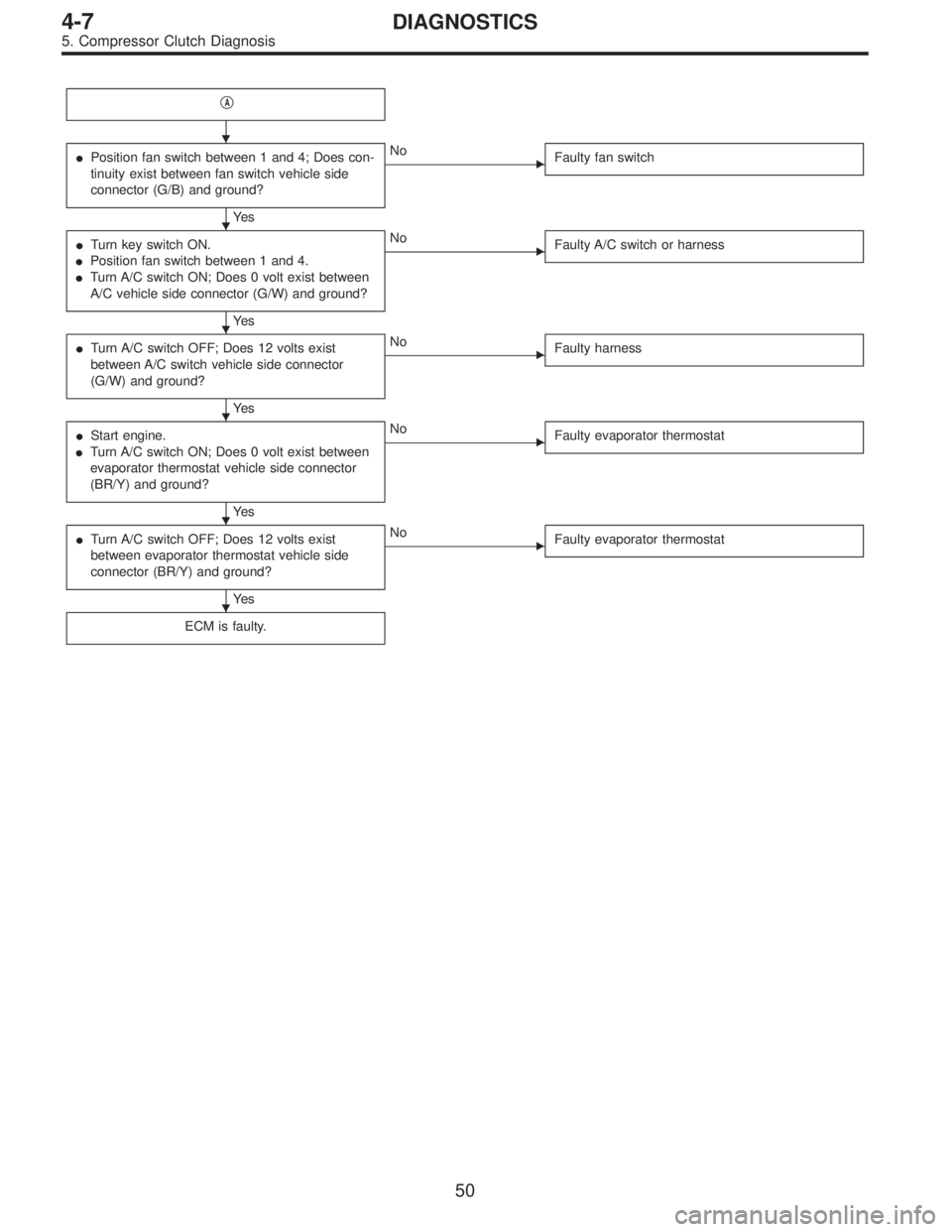
�A
�Position fan switch between 1 and 4; Does con-
tinuity exist between fan switch vehicle side
connector (G/B) and ground?
Ye s
�No
Faulty fan switch
�Turn key switch ON.
�Position fan switch between 1 and 4.
�Turn A/C switch ON; Does 0 volt exist between
A/C vehicle side connector (G/W) and ground?
Ye s
�No
Faulty A/C switch or harness
�Turn A/C switch OFF; Does 12 volts exist
between A/C switch vehicle side connector
(G/W) and ground?
Ye s
�No
Faulty harness
�Start engine.
�Turn A/C switch ON; Does 0 volt exist between
evaporator thermostat vehicle side connector
(BR/Y) and ground?
Ye s
�No
Faulty evaporator thermostat
�Turn A/C switch OFF; Does 12 volts exist
between evaporator thermostat vehicle side
connector (BR/Y) and ground?
Ye s
�No
Faulty evaporator thermostat
ECM is faulty.
�
�
�
�
�
�
50
4-7DIAGNOSTICS
5. Compressor Clutch Diagnosis
Page 950 of 2248
G5M0144
2. Trunk Lid
A: REMOVAL
1. TRUNK LID
1) Open trunk lid.
2) Remove trunk lid mounting bolts and detach trunk lid
from hinges.
G5M0145
2. TORSION BAR
1) Open trunk lid. Remove torsion bars from hinge links
using ST.
ST 927780000 REMOVER
CAUTION:
Be careful because torsion bar quickly swings back
when released.
2) Remove the left and right torsion bars.
WARNING:
Be careful because trunk lid drops under its own
weight when torsion bars are removed.
G5M0146
3. TRUNK LID LOCK ASSEMBLY AND KEY
CYLINDER
1) Remove rod of lock assembly from rod holder of key
lock assembly.
2) Remove nuts which hold lock assembly and remove
lock assembly.
NOTE:
�Always remove rear skirt trim panel beforehand, if so
equipped.
�Be careful not to bend opener cable.
B5M0269A
3) Remove rod holder and detach key cylinder from trunk
lid.
33
5-1SERVICE PROCEDURE
2. Trunk Lid
Page 982 of 2248
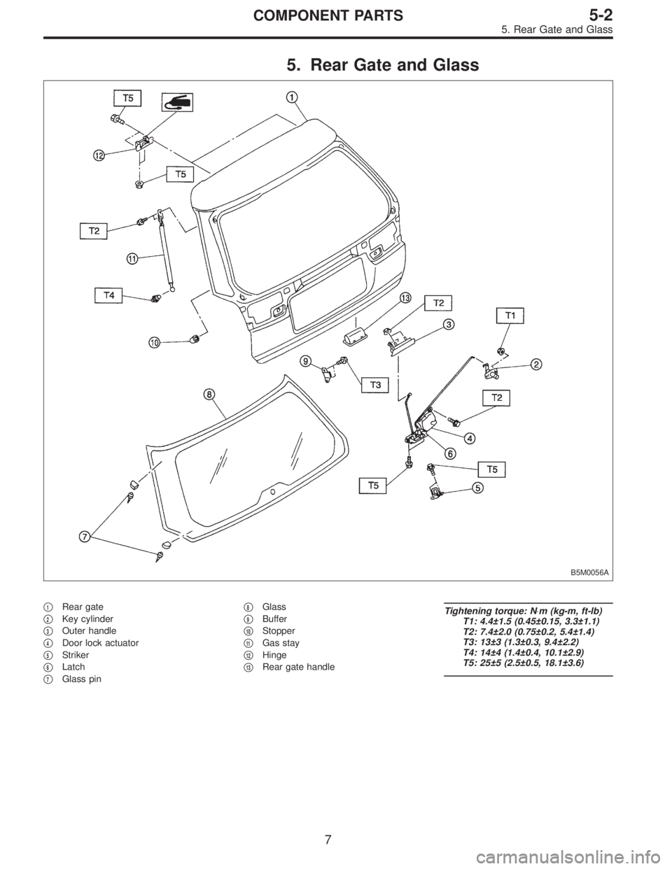
5. Rear Gate and Glass
B5M0056A
�1Rear gate
�
2Key cylinder
�
3Outer handle
�
4Door lock actuator
�
5Striker
�
6Latch
�
7Glass pin�
8Glass
�
9Buffer
�
10Stopper
�
11Gas stay
�
12Hinge
�
13Rear gate handle
Tightening torque: N⋅m (kg-m, ft-lb)
T1: 4.4±1.5 (0.45±0.15, 3.3±1.1)
T2: 7.4±2.0 (0.75±0.2, 5.4±1.4)
T3: 13±3 (1.3±0.3, 9.4±2.2)
T4: 14±4 (1.4±0.4, 10.1±2.9)
T5: 25±5 (2.5±0.5, 18.1±3.6)
7
5-2COMPONENT PARTS
5. Rear Gate and Glass
 Press FD1 ENT key.
B4M0634
5) The message shown in the figure is displayed as fol-
lows:
(1) When using the brake tester, depress brake pedal
with braking force of 981 to 1,471 N (100 to 15")

![SUBARU LEGACY 1995 Service Repair Manual 2. OPERATIONAL GUIDELINES OF THE TCS
SEQUENCE CONTROL WITH SELECT MONITOR
1) Connect select monitor to data link connector beside
driver’s seat heater unit. <Ref. to [W19D0] step 1).>
2) Engine star](/manual-img/17/57432/w960_57432-814.png "SUBARU LEGACY 1995 Service Repair Manual 2. OPERATIONAL GUIDELINES OF THE TCS
SEQUENCE CONTROL WITH SELECT MONITOR
1) Connect select monitor to data link connector beside
driver’s seat heater unit. <Ref. to [W19D0] step 1).>
2) Engine star")

 Open trunk lid.
2) Remove trunk lid mounting bolts and detach trunk lid
from hinges.
G5M0145
2. TORSION BAR
1) Open trunk lid. Remove torsion bars from")