Page 480 of 2248
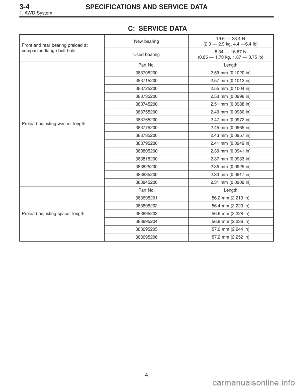
C: SERVICE DATA
Front and rear bearing preload at
companion flange bolt holeNew bearing19.6 — 28.4 N
(2.0 — 2.9 kg, 4.4 —6.4 lb)
Used bearing8.34 — 16.67 N
(0.85 — 1.70 kg, 1.87 — 3.75 lb)
Preload adjusting washer lengthPart No. Length
383705200 2.59 mm (0.1020 in)
383715200 2.57 mm (0.1012 in)
383725200 2.55 mm (0.1004 in)
383735200 2.53 mm (0.0996 in)
383745200 2.51 mm (0.0988 in)
383755200 2.49 mm (0.0980 in)
383765200 2.47 mm (0.0972 in)
383775200 2.45 mm (0.0965 in)
383785200 2.43 mm (0.0957 in)
383795200 2.41 mm (0.0949 in)
383805200 2.39 mm (0.0941 in)
383815200 2.37 mm (0.0933 in)
383825200 2.35 mm (0.0925 in)
383835200 2.33 mm (0.0917 in)
383845200 2.31 mm (0.0909 in)
Preload adjusting spacer lengthPart No. Length
383695201 56.2 mm (2.213 in)
383695202 56.4 mm (2.220 in)
383695203 56.6 mm (2.228 in)
383695204 56.8 mm (2.236 in)
383695205 57.0 mm (2.244 in)
383695206 57.2 mm (2.252 in)
4
3-4SPECIFICATIONS AND SERVICE DATA
1. AWD System
Page 504 of 2248
G3M1038
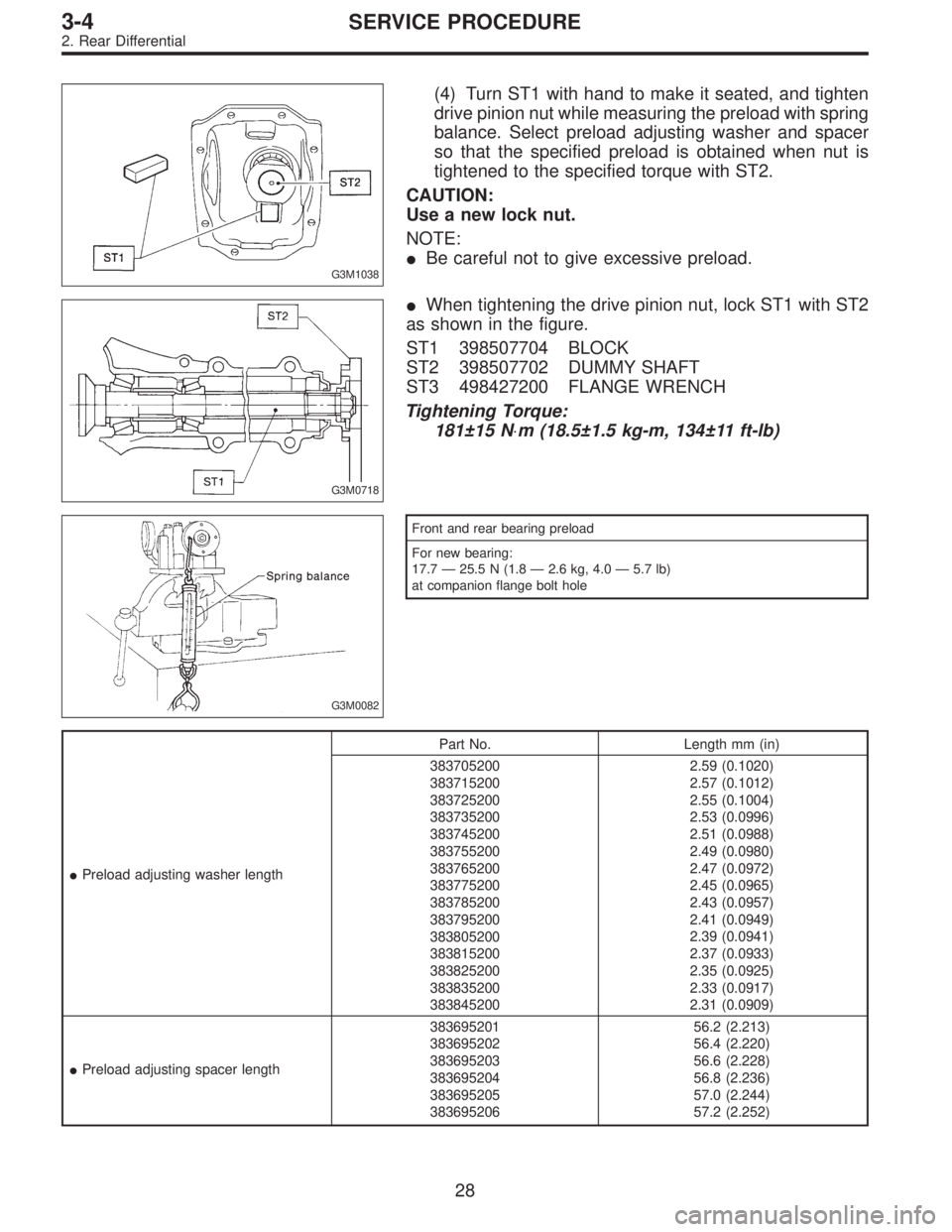
(4) Turn ST1 with hand to make it seated, and tighten
drive pinion nut while measuring the preload with spring
balance. Select preload adjusting washer and spacer
so that the specified preload is obtained when nut is
tightened to the specified torque with ST2.
CAUTION:
Use a new lock nut.
NOTE:
�Be careful not to give excessive preload.
G3M0718
�When tightening the drive pinion nut, lock ST1 with ST2
as shown in the figure.
ST1 398507704 BLOCK
ST2 398507702 DUMMY SHAFT
ST3 498427200 FLANGE WRENCH
Tightening Torque:
181±15 N⋅m (18.5±1.5 kg-m, 134±11 ft-lb)
G3M0082
Front and rear bearing preload
For new bearing:
17.7—25.5 N (1.8—2.6 kg, 4.0—5.7 lb)
at companion flange bolt hole
�Preload adjusting washer lengthPart No. Length mm (in)
383705200
383715200
383725200
383735200
383745200
383755200
383765200
383775200
383785200
383795200
383805200
383815200
383825200
383835200
3838452002.59 (0.1020)
2.57 (0.1012)
2.55 (0.1004)
2.53 (0.0996)
2.51 (0.0988)
2.49 (0.0980)
2.47 (0.0972)
2.45 (0.0965)
2.43 (0.0957)
2.41 (0.0949)
2.39 (0.0941)
2.37 (0.0933)
2.35 (0.0925)
2.33 (0.0917)
2.31 (0.0909)
�Preload adjusting spacer length383695201
383695202
383695203
383695204
383695205
38369520656.2 (2.213)
56.4 (2.220)
56.6 (2.228)
56.8 (2.236)
57.0 (2.244)
57.2 (2.252)
28
3-4SERVICE PROCEDURE
2. Rear Differential
Page 563 of 2248
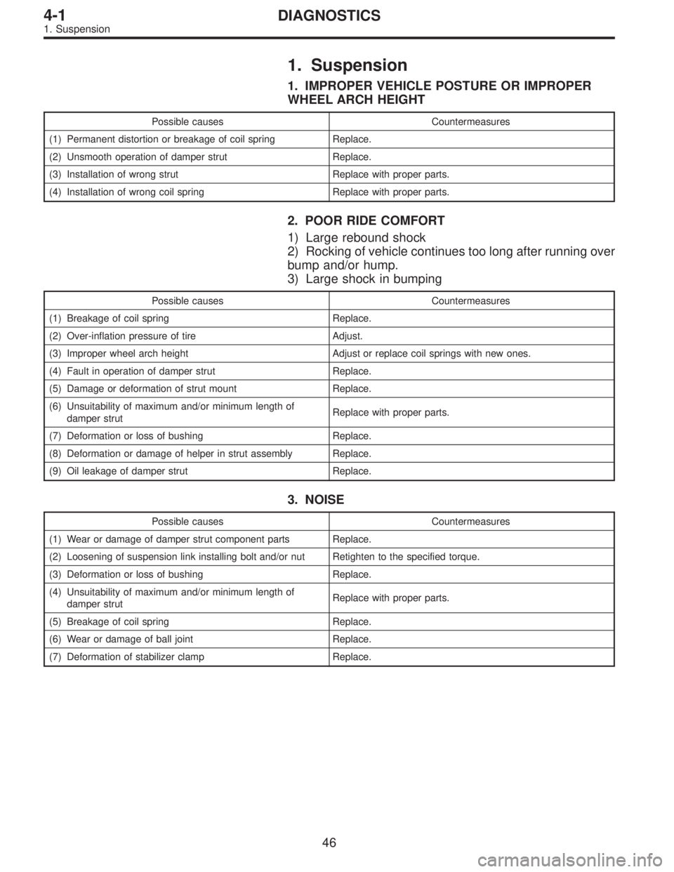
1. Suspension
1. IMPROPER VEHICLE POSTURE OR IMPROPER
WHEEL ARCH HEIGHT
Possible causes Countermeasures
(1) Permanent distortion or breakage of coil spring Replace.
(2) Unsmooth operation of damper strut Replace.
(3) Installation of wrong strut Replace with proper parts.
(4) Installation of wrong coil spring Replace with proper parts.
2. POOR RIDE COMFORT
1) Large rebound shock
2) Rocking of vehicle continues too long after running over
bump and/or hump.
3) Large shock in bumping
Possible causes Countermeasures
(1) Breakage of coil spring Replace.
(2) Over-inflation pressure of tire Adjust.
(3) Improper wheel arch height Adjust or replace coil springs with new ones.
(4) Fault in operation of damper strut Replace.
(5) Damage or deformation of strut mount Replace.
(6) Unsuitability of maximum and/or minimum length of
damper strutReplace with proper parts.
(7) Deformation or loss of bushing Replace.
(8) Deformation or damage of helper in strut assembly Replace.
(9) Oil leakage of damper strut Replace.
3. NOISE
Possible causes Countermeasures
(1) Wear or damage of damper strut component parts Replace.
(2) Loosening of suspension link installing bolt and/or nut Retighten to the specified torque.
(3) Deformation or loss of bushing Replace.
(4) Unsuitability of maximum and/or minimum length of
damper strutReplace with proper parts.
(5) Breakage of coil spring Replace.
(6) Wear or damage of ball joint Replace.
(7) Deformation of stabilizer clamp Replace.
46
4-1DIAGNOSTICS
1. Suspension
Page 615 of 2248
G4M0301
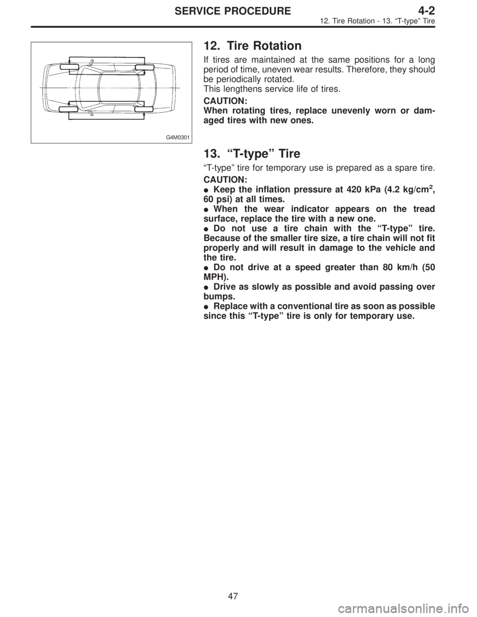
12. Tire Rotation
If tires are maintained at the same positions for a long
period of time, uneven wear results. Therefore, they should
be periodically rotated.
This lengthens service life of tires.
CAUTION:
When rotating tires, replace unevenly worn or dam-
aged tires with new ones.
13.“T-type”Tire
“T-type”tire for temporary use is prepared as a spare tire.
CAUTION:
�Keep the inflation pressure at 420 kPa (4.2 kg/cm
2,
60 psi) at all times.
�When the wear indicator appears on the tread
surface, replace the tire with a new one.
�Do not use a tire chain with the“T-type”tire.
Because of the smaller tire size, a tire chain will not fit
properly and will result in damage to the vehicle and
the tire.
�Do not drive at a speed greater than 80 km/h (50
MPH).
�Drive as slowly as possible and avoid passing over
bumps.
�Replace with a conventional tire as soon as possible
since this“T-type”tire is only for temporary use.
47
4-2SERVICE PROCEDURE
12. Tire Rotation - 13.“T-type”Tire
Page 616 of 2248
G4M0301
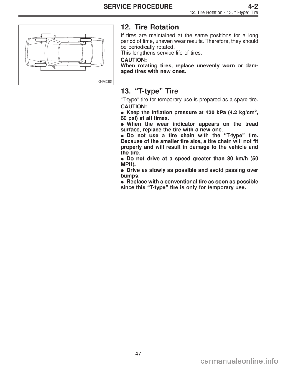
12. Tire Rotation
If tires are maintained at the same positions for a long
period of time, uneven wear results. Therefore, they should
be periodically rotated.
This lengthens service life of tires.
CAUTION:
When rotating tires, replace unevenly worn or dam-
aged tires with new ones.
13.“T-type”Tire
“T-type”tire for temporary use is prepared as a spare tire.
CAUTION:
�Keep the inflation pressure at 420 kPa (4.2 kg/cm
2,
60 psi) at all times.
�When the wear indicator appears on the tread
surface, replace the tire with a new one.
�Do not use a tire chain with the“T-type”tire.
Because of the smaller tire size, a tire chain will not fit
properly and will result in damage to the vehicle and
the tire.
�Do not drive at a speed greater than 80 km/h (50
MPH).
�Drive as slowly as possible and avoid passing over
bumps.
�Replace with a conventional tire as soon as possible
since this“T-type”tire is only for temporary use.
47
4-2SERVICE PROCEDURE
12. Tire Rotation - 13.“T-type”Tire
Page 628 of 2248
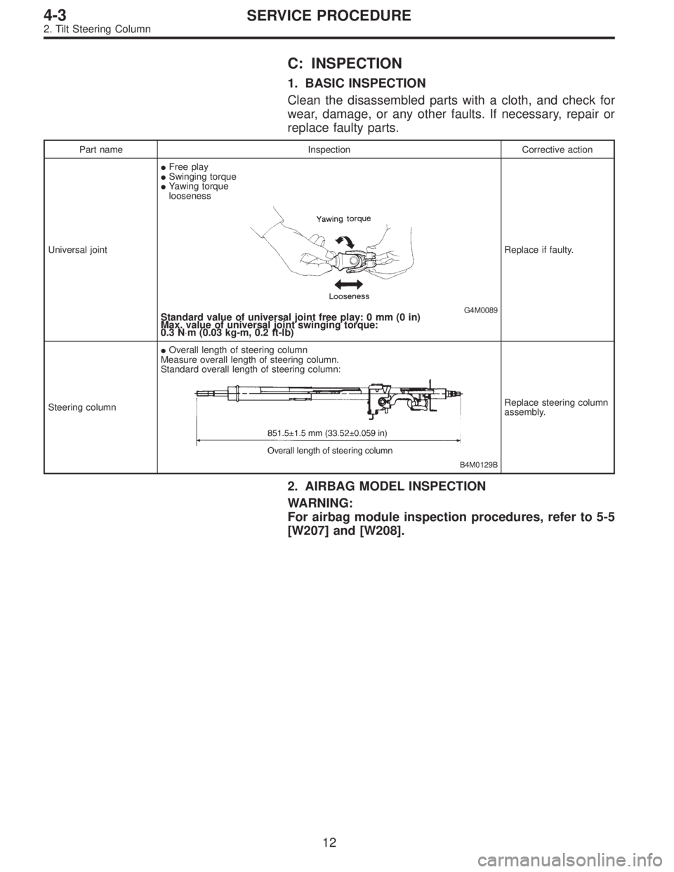
C: INSPECTION
1. BASIC INSPECTION
Clean the disassembled parts with a cloth, and check for
wear, damage, or any other faults. If necessary, repair or
replace faulty parts.
Part name Inspection Corrective action
Universal joint�Free play
�Swinging torque
�Yawing torque
looseness
G4M0089Standard value of universal joint free play: 0 mm (0 in)
Max. value of universal joint swinging torque:
0.3 N⋅m (0.03 kg-m, 0.2 ft-lb)
Replace if faulty.
Steering column�Overall length of steering column
Measure overall length of steering column.
Standard overall length of steering column:
B4M0129B
Replace steering column
assembly.
2. AIRBAG MODEL INSPECTION
WARNING:
For airbag module inspection procedures, refer to 5-5
[W207] and [W208].
12
4-3SERVICE PROCEDURE
2. Tilt Steering Column
Page 641 of 2248
G4M0126
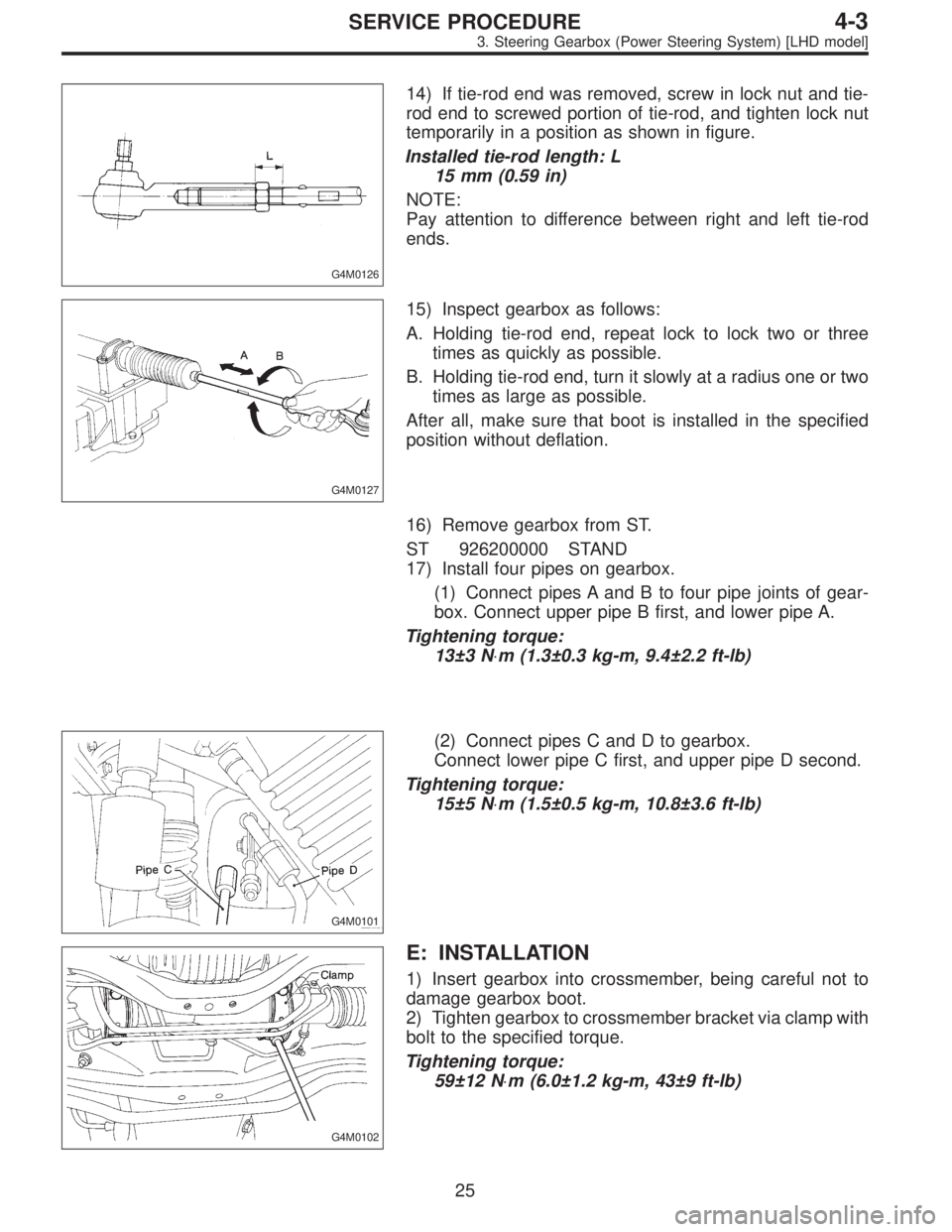
14) If tie-rod end was removed, screw in lock nut and tie-
rod end to screwed portion of tie-rod, and tighten lock nut
temporarily in a position as shown in figure.
Installed tie-rod length: L
15 mm (0.59 in)
NOTE:
Pay attention to difference between right and left tie-rod
ends.
G4M0127
15) Inspect gearbox as follows:
A. Holding tie-rod end, repeat lock to lock two or three
times as quickly as possible.
B. Holding tie-rod end, turn it slowly at a radius one or two
times as large as possible.
After all, make sure that boot is installed in the specified
position without deflation.
16) Remove gearbox from ST.
ST 926200000 STAND
17) Install four pipes on gearbox.
(1) Connect pipes A and B to four pipe joints of gear-
box. Connect upper pipe B first, and lower pipe A.
Tightening torque:
13±3 N⋅m (1.3±0.3 kg-m, 9.4±2.2 ft-lb)
G4M0101
(2) Connect pipes C and D to gearbox.
Connect lower pipe C first, and upper pipe D second.
Tightening torque:
15±5 N⋅m (1.5±0.5 kg-m, 10.8±3.6 ft-lb)
G4M0102
E: INSTALLATION
1) Insert gearbox into crossmember, being careful not to
damage gearbox boot.
2) Tighten gearbox to crossmember bracket via clamp with
bolt to the specified torque.
Tightening torque:
59±12 N⋅m (6.0±1.2 kg-m, 43±9 ft-lb)
25
4-3SERVICE PROCEDURE
3. Steering Gearbox (Power Steering System) [LHD model]
Page 700 of 2248
1. Power Steering
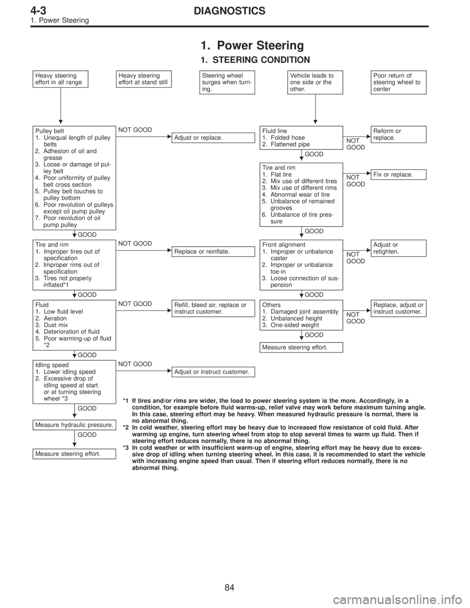
1. STEERING CONDITION
Heavy steering
effort in all rangeHeavy steering
effort at stand stillSteering wheel
surges when turn-
ing.Vehicle leads to
one side or the
other.Poor return of
steering wheel to
center
Pulley belt
1. Unequal length of pulley
belts
2. Adhesion of oil and
grease
3. Loose or damage of pul-
ley belt
4. Poor uniformity of pulley
belt cross section
5. Pulley belt touches to
pulley bottom
6. Poor revolution of pulleys
except oil pump pulley
7. Poor revolution of oil
pump pulley
GOOD
�NOT GOOD
Adjust or replace.Fluid line
1. Folded hose
2. Flattened pipe
GOOD
�NOT
GOODReform or
replace.
Tire and rim
1. Flat tire
2. Mix use of different tires
3. Mix use of different rims
4. Abnormal wear of tire
5. Unbalance of remained
grooves
6. Unbalance of tire pres-
sure
GOOD
�NOT
GOODFix or replace.
Tire and rim
1. Improper tires out of
specification
2. Improper rims out of
specification
3. Tires not properly
inflated*1
GOOD
�NOT GOOD
Replace or reinflate.Front alignment
1. Improper or unbalance
caster
2. Improper or unbalance
toe-in
3. Loose connection of sus-
pension
GOOD
�NOT
GOODAdjust or
retighten.
Fluid
1. Low fluid level
2. Aeration
3. Dust mix
4. Deterioration of fluid
5. Poor warming-up of fluid
*2
GOOD
�NOT GOOD
Refill, bleed air, replace or
instruct customer.Others
1. Damaged joint assembly
2. Unbalanced height
3. One-sided weight
GOOD
Measure steering effort.
�NOT
GOODReplace, adjust or
instruct customer.
Idling speed
1. Lower idling speed
2. Excessive drop of
idling speed at start
or at turning steering
wheel *3
GOOD
�NOT GOOD
Adjust or instruct customer.
*1 If tires and/or rims are wider, the load to power steering system is the more. Accordingly, in a
condition, for example before fluid warms-up, relief valve may work before maximum turning angle.
In this case, steering effort may be heavy. When measured hydraulic pressure is normal, there is
no abnormal thing.
*2 In cold weather, steering effort may be heavy due to increased flow resistance of cold fluid. After
warming up engine, turn steering wheel from stop to stop several times to warm up fluid. Then if
steering effort reduces normally, there is no abnormal thing.
*3 In cold weather or with insufficient warm-up of engine, steering effort may be heavy due to exces-
sive drop of idling when turning steering wheel. In this case, it is recommended to start the vehicle
with increasing engine speed than usual. Then if steering effort reduces normally, there is no
abnormal thing. Measure hydraulic pressure.
GOOD
Measure steering effort.
��
�
��
��
�
�
�
�
84
4-3DIAGNOSTICS
1. Power Steering