Page 774 of 2248
12. Brake Fluid Replacement
NOTE:
To always maintain the brake fluid characteristics, replace
the brake fluid according to maintenance schedule or ear-
lier than that when used in severe condition.
A: REPLACEMENT
CAUTION:
�The FMVSS No. 116, fresh DOT3 or 4 brake fluid
must be used.
�Cover bleeder with waste cloth, when loosening it,
to prevent brake fluid from being splashed over sur-
rounding parts.
�Avoid mixing different brands of brake fluid to pre-
vent degrading the quality of the fluid.
�Be careful not to allow dirt or dust to get into the
reservoir tank.
NOTE:
�During bleeding operation, keep the brake reserve tank
filled with brake fluid to eliminate entry of air.
�Brake pedal operating must be very slow.
�For convenience and safety, it is advisable to have two
man working.
�The amount of brake fluid required is approximately 500
m�(16.9 US fl oz, 17.6 Imp fl oz) for total brake system.
1) Either jack-up vehicle and place a safety stand under it,
or lift-up vehicle.
2) Remove both front and rear wheels.
3) Draw out the brake fluid from reserve tank with syringe.
4) Refill reservoir tank with recommended brake fluid.
Recommended brake fluid:
FMVSS No. 116, fresh DOT3 or 4 brake fluid
57
4-4SERVICE PROCEDURE
12. Brake Fluid Replacement
Page 775 of 2248

G4M0434
G4M0438
G4M0435
5) Install one end of a vinyl tube onto the air bleeder of and
insert the other end of the tube into a container to collect
the brake fluid.
6) Instruct your co-worker to depress the brake pedal
slowly two or three times and then hold it depressed.
7) Loosen bleeder screw approximately 1/4 turn until a
small amount of brake fluid drains into container, and then
quickly tighten screw.
8) Repeat steps 6) and 7) above until there are no air
bubbles in drained brake fluid and new fluid flows through
vinyl tube.
CAUTION:
Add brake fluid as necessary while performing the air
bleed operation, in order to prevent the tank from run-
ning short of brake fluid.
9) After completing the bleeding operation, hold brake
pedal depressed and tighten screw and install bleeder cap.
Tightening torque (Bleeder screw):
8±1 N⋅m (0.8±0.1 kg-m, 5.8±0.7 ft-lb)
10) Bleed air from each wheel cylinder using the same
procedures as described in steps 6) through 7) above.
11) Depress brake pedal with a force of approximately 294
N (30 kg, 66 lb) and hold it there for approximately 20 sec-
onds. At this time check pedal to see if it shows any
unusual movement.
Visually inspect bleeder screws and brake pipe joints to
make sure that there is no fluid leakage.
12) Install wheels, and drive vehicle for a short distance
between 2 to 3 km (1 to 2 miles) to make sure that brakes
are operating properly.
58
4-4SERVICE PROCEDURE
12. Brake Fluid Replacement
Page 1135 of 2248
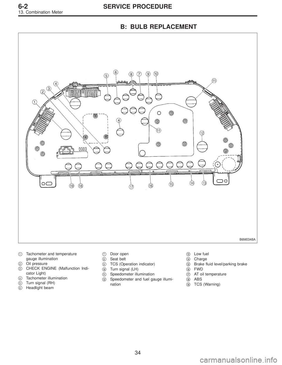
B: BULB REPLACEMENT
B6M0348A
�1Tachometer and temperature
gauge illumination
�
2Oil pressure
�
3CHECK ENGINE (Malfunction Indi-
cator Light)
�
4Tachometer illumination
�
5Turn signal (RH)
�
6Headlight beam�
7Door open
�
8Seat belt
�
9TCS (Operation indicator)
�
10Turn signal (LH)
�
11Speedometer illumination
�
12Speedometer and fuel gauge illumi-
nation�
13Low fuel
�
14Charge
�
15Brake fluid level/parking brake
�
16FWD
�
17AT oil temperature
�
18ABS
�
19TCS (Warning)
34
6-2SERVICE PROCEDURE
13. Combination Meter
Page 1486 of 2248
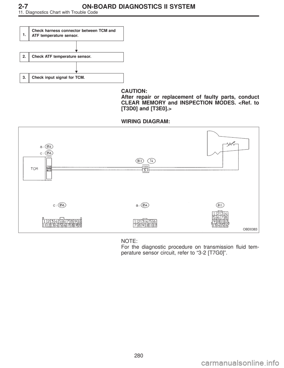
1.Check harness connector between TCM and
ATF temperature sensor.
2.Check ATF temperature sensor.
3.Check input signal for TCM.
CAUTION:
After repair or replacement of faulty parts, conduct
CLEAR MEMORY and INSPECTION MODES.
[T3D0] and [T3E0].>
WIRING DIAGRAM:
OBD0383
NOTE:
For the diagnostic procedure on transmission fluid tem-
perature sensor circuit, refer to“3-2 [T7G0]”.
�
�
280
2-7ON-BOARD DIAGNOSTICS II SYSTEM
11. Diagnostics Chart with Trouble Code