Page 557 of 2248
G4M0538
7) Models equipped with rear disc brakes:
Remove union bolt from brake caliper.
8) Models equipped with rear drum brakes:
Disconnect brake hose from brake pipe from strut, and
disconnect brake pipe from dram brake.
G4M0539
9) Remove bolts which secure rear strut to housing.
10) Remove nuts securing strut mount to body.
11) Remove strut mount cap.
B: DISASSEMBLY
For disassembly of rear strut, refer to procedures outlined
under front strut as a guide.
C: INSPECTION
Refer to Front Strut as a guide for inspection procedures.
G4M0540
D: ASSEMBLY
Refer to Front Strut as a guide for assembly procedures.
CAUTION:
�Install rear strut with “FWD” or “4WD” mark on strut
mount facing outside of vehicle body.
�Insert the protrusion of lower rubber seat into the
strut spring seat hole.
40
4-1SERVICE PROCEDURE
9. Rear Strut
Page 1257 of 2248
6. READ DATA FUNCTION KEY LIST FOR AT
Function mode Contents Abbr. Unit
F00 Mode display——
F01 Battery voltage VB V
F02 Vehicle speed sensor 1 VSP1 m/h
F03 Vehicle speed sensor 1 VSP1 km/h
F04 Vehicle speed sensor 2 VSP2 m/h
F05 Vehicle speed sensor 2 VSP2 km/h
F06 Engine speed EREV rpm
F07 ATF temperature sensor ATFT deg F
F08 ATF temperature sensor ATFT deg C
F09 Throttle position sensor THV V
F10 Gear position GEAR—
F11 Line pressure duty PLDTY %
F12 Lock-up duty LUDTY %
F13 AWD duty 4WDTY %
F14 Throttle position sensor power supply THVCC V
F15 Mass air flow sensor AFM V
51
2-7ON-BOARD DIAGNOSTICS II SYSTEM
3. Diagnosis System
Page 1260 of 2248
G3M0730
�FUNCTION MODE: F10
—GEAR POSITION (GEAR)—
G3M0731
�FUNCTION MODE: F11
—LINE PRESSURE DUTY (PLDTY)—
G3M0732
�FUNCTION MODE: F12
—LOCK-UP DUTY (LUDTY)—
G3M0733
�FUNCTION MODE: F13
—AWD DUTY (4WDTY)—
B3M0259
�FUNCTION MODE: F14
—THROTTLE POSITION SENSOR POWER
SUPPLY (THVCC)—
54
2-7ON-BOARD DIAGNOSTICS II SYSTEM
3. Diagnosis System
Page 1568 of 2248

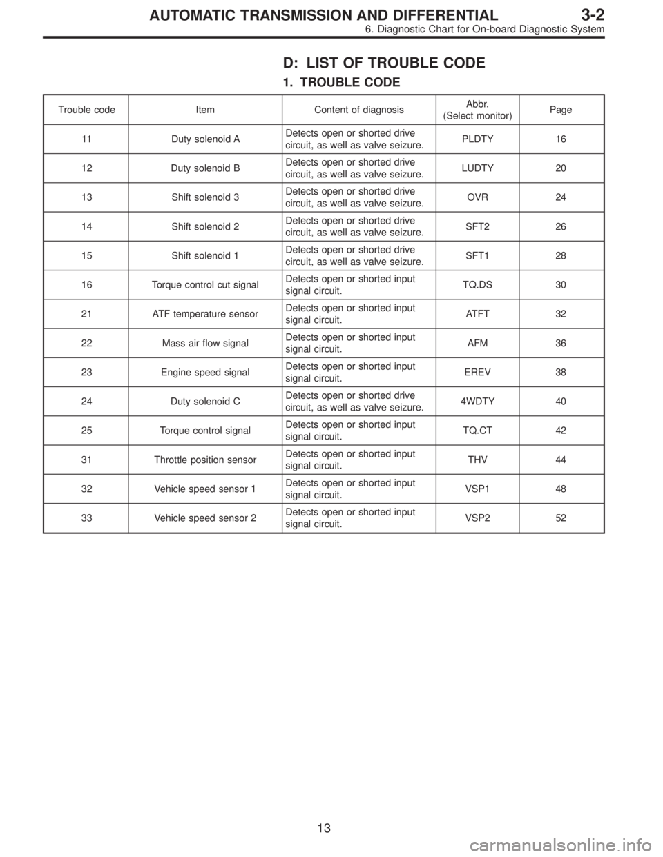
D: LIST OF TROUBLE CODE
1. TROUBLE CODE
Trouble code Item Content of diagnosisAbbr.
(Select monitor)Page
11 Duty solenoid ADetects open or shorted drive
circuit, as well as valve seizure.PLDTY 16
12 Duty solenoid BDetects open or shorted drive
circuit, as well as valve seizure.LUDTY 20
13 Shift solenoid 3Detects open or shorted drive
circuit, as well as valve seizure.OVR 24
14 Shift solenoid 2Detects open or shorted drive
circuit, as well as valve seizure.SFT2 26
15 Shift solenoid 1Detects open or shorted drive
circuit, as well as valve seizure.SFT1 28
16 Torque control cut signalDetects open or shorted input
signal circuit.TQ.DS 30
21 ATF temperature sensorDetects open or shorted input
signal circuit.ATFT 32
22 Mass air flow signalDetects open or shorted input
signal circuit.AFM 36
23 Engine speed signalDetects open or shorted input
signal circuit.EREV 38
24 Duty solenoid CDetects open or shorted drive
circuit, as well as valve seizure.4WDTY 40
25 Torque control signalDetects open or shorted input
signal circuit.TQ.CT 42
31 Throttle position sensorDetects open or shorted input
signal circuit.THV 44
32 Vehicle speed sensor 1Detects open or shorted input
signal circuit.VSP1 48
33 Vehicle speed sensor 2Detects open or shorted input
signal circuit.VSP2 52
13
3-2AUTOMATIC TRANSMISSION AND DIFFERENTIAL
6. Diagnostic Chart for On-board Diagnostic System
Page 1611 of 2248

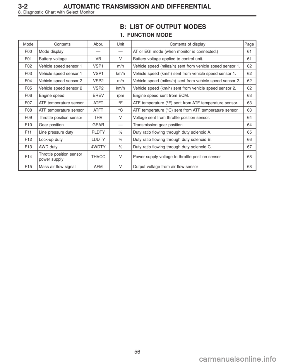
B: LIST OF OUTPUT MODES
1. FUNCTION MODE
Mode Contents Abbr. Unit Contents of display Page
F00 Mode display——AT or EGI mode (when monitor is connected.) 61
F01 Battery voltage VB V Battery voltage applied to control unit. 61
F02 Vehicle speed sensor 1 VSP1 m/h Vehicle speed (miles/h) sent from vehicle speed sensor 1. 62
F03 Vehicle speed sensor 1 VSP1 km/h Vehicle speed (km/h) sent from vehicle speed sensor 1. 62
F04 Vehicle speed sensor 2 VSP2 m/h Vehicle speed (miles/h) sent from vehicle speed sensor 2. 62
F05 Vehicle speed sensor 2 VSP2 km/h Vehicle speed (km/h) sent from vehicle speed sensor 2. 62
F06 Engine speed EREV rpm Engine speed sent from ECM. 63
F07 ATF temperature sensor ATFT°F ATF temperature (°F) sent from ATF temperature sensor. 63
F08 ATF temperature sensor ATFT°C ATF temperature (°C) sent from ATF temperature sensor. 63
F09 Throttle position sensor THV V Voltage sent from throttle position sensor. 64
F10 Gear position GEAR—Transmission gear position 64
F11 Line pressure duty PLDTY % Duty ratio flowing through duty solenoid A. 65
F12 Lock-up duty LUDTY % Duty ratio flowing through duty solenoid B. 66
F13 AWD duty 4WDTY % Duty ratio flowing through duty solenoid C. 67
F14Throttle position sensor
power supplyTHVCC V Power supply voltage to throttle position sensor 68
F15 Mass air flow signal AFM V Output voltage from air flow sensor 68
56
3-2AUTOMATIC TRANSMISSION AND DIFFERENTIAL
8. Diagnostic Chart with Select Monitor
Page 1619 of 2248
G3M0733
M: MODE F13—AWD DUTY (4WDTY)—
CONDITION:
�After sufficient warm-up
�Ignition switch ON (engine OFF)
�FWD mode
�AWD mode, D range, full throttle
SPECIFIED DATA:
�95% (FWD mode)
�25%, max. (vehicle speed 0 m/h) (AWD mode)
Probable cause (if outside“specified data”)
1. Throttle position sensor
�Check in F09 mode.
OK
2. Vehicle speed sensor 1
�Check in F02 mode.
OK
3. Vehicle speed sensor 2
�Check in F04 mode.
OK
4. ATF temperature sensor
�Check in F07 mode.
OK
5. Inhibitor switch
�Check for operation.
OK
6. ABS signal
�Check ABS system for operation.
OK
Check TCM and replace if necessary.
�
�
�
�
�
�
64
3-2AUTOMATIC TRANSMISSION AND DIFFERENTIAL
8. Diagnostic Chart with Select Monitor