Page 1304 of 2248
13. FLOOR WIRING HARNESS, DOOR CORD AND
GROUND POINT (LHD MODEL)
OBD0735
98
2-7ON-BOARD DIAGNOSTICS II SYSTEM
6. Wiring Diagram and Wiring Harness
Page 1305 of 2248
14. DOOR CORD AND GROUND POINT (RHD
MODEL)
B2M0444
99
2-7ON-BOARD DIAGNOSTICS II SYSTEM
6. Wiring Diagram and Wiring Harness
Page 1310 of 2248
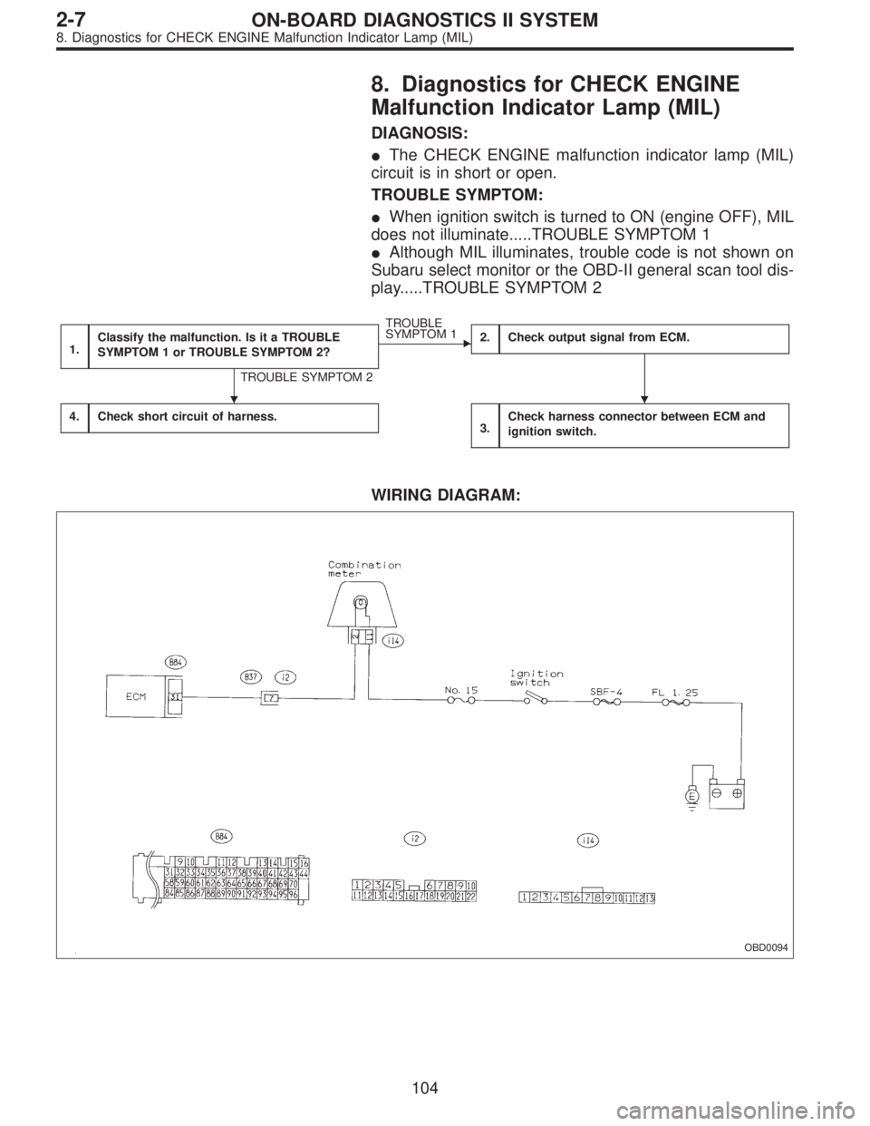
8. Diagnostics for CHECK ENGINE
Malfunction Indicator Lamp (MIL)
DIAGNOSIS:
�The CHECK ENGINE malfunction indicator lamp (MIL)
circuit is in short or open.
TROUBLE SYMPTOM:
�When ignition switch is turned to ON (engine OFF), MIL
does not illuminate.....TROUBLE SYMPTOM 1
�Although MIL illuminates, trouble code is not shown on
Subaru select monitor or the OBD-II general scan tool dis-
play.....TROUBLE SYMPTOM 2
1.Classify the malfunction. Is it a TROUBLE
SYMPTOM 1 or TROUBLE SYMPTOM 2?
TROUBLE SYMPTOM 2
�
TROUBLE
SYMPTOM 1
2.Check output signal from ECM.
4.Check short circuit of harness.3.Check harness connector between ECM and
ignition switch.
WIRING DIAGRAM:
OBD0094
��
104
2-7ON-BOARD DIAGNOSTICS II SYSTEM
8. Diagnostics for CHECK ENGINE Malfunction Indicator Lamp (MIL)
Page 1311 of 2248

1CLASSIFY THE MALFUNCTION. IS IT A
TROUBLE SYMPTOM 1 OR TROUBLE SYMP-
TOM 2?
If the malfunction shows TROUBLE SYMPTOM 1, go to
step 2.
If the malfunction shows TROUBLE SYMPTOM 2, go to
step 4.
OBD0095A
2
CHECK OUTPUT SIGNAL FROM ECM.
1) Turn ignition switch to ON.
2) Measure voltage between ECM and body.
: Connector & terminal
(B84) No. 31 — Body/1 V, or less
: Go to step 3.
:�If MIL comes on when shaking or pulling ECM
connector and harness, repair ECM connector.
�Check that ECM connector is correctly con-
nected. If the MIL does not come on even when
ECM connector is correctly connected, replace
the ECM.
OBD0096
3CHECK HARNESS CONNECTOR BETWEEN
ECM AND IGNITION SWITCH.
Check the following and repair if necessary.
�
1Check that fuse (No. 15) is not blown out.
NOTE:
If replaced fuse (No. 15) blows out easily, check the har-
ness for short circuit between fuse (No. 15) and combina-
tion meter.
�
2Check that harness from fuse to combination meter is
not open.
�
3Check that the MIL wiring is not open.
�
4Check that harness from combination meter to the ECM
is not open.
�
5Check that the connector (B37) is correctly connected
as the wiring diagram shows.
105
2-7ON-BOARD DIAGNOSTICS II SYSTEM
8. Diagnostics for CHECK ENGINE Malfunction Indicator Lamp (MIL)
Page 1314 of 2248
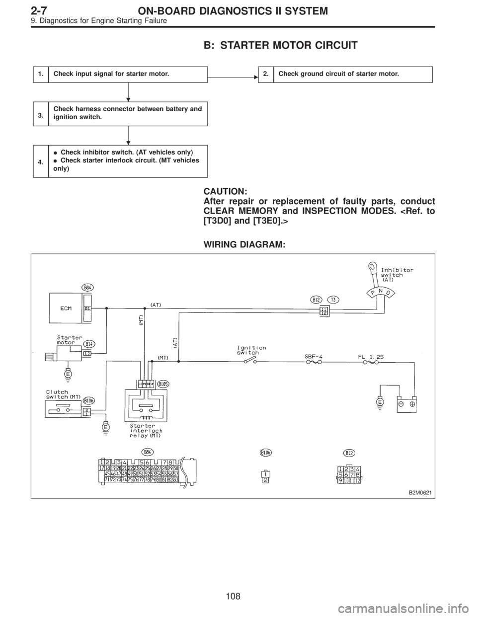
B: STARTER MOTOR CIRCUIT
1.Check input signal for starter motor.�2.Check ground circuit of starter motor.
3.Check harness connector between battery and
ignition switch.
4.
�Check inhibitor switch. (AT vehicles only)
�Check starter interlock circuit. (MT vehicles
only)
CAUTION:
After repair or replacement of faulty parts, conduct
CLEAR MEMORY and INSPECTION MODES.
[T3D0] and [T3E0].>
WIRING DIAGRAM:
B2M0621
�
�
108
2-7ON-BOARD DIAGNOSTICS II SYSTEM
9. Diagnostics for Engine Starting Failure
Page 1318 of 2248
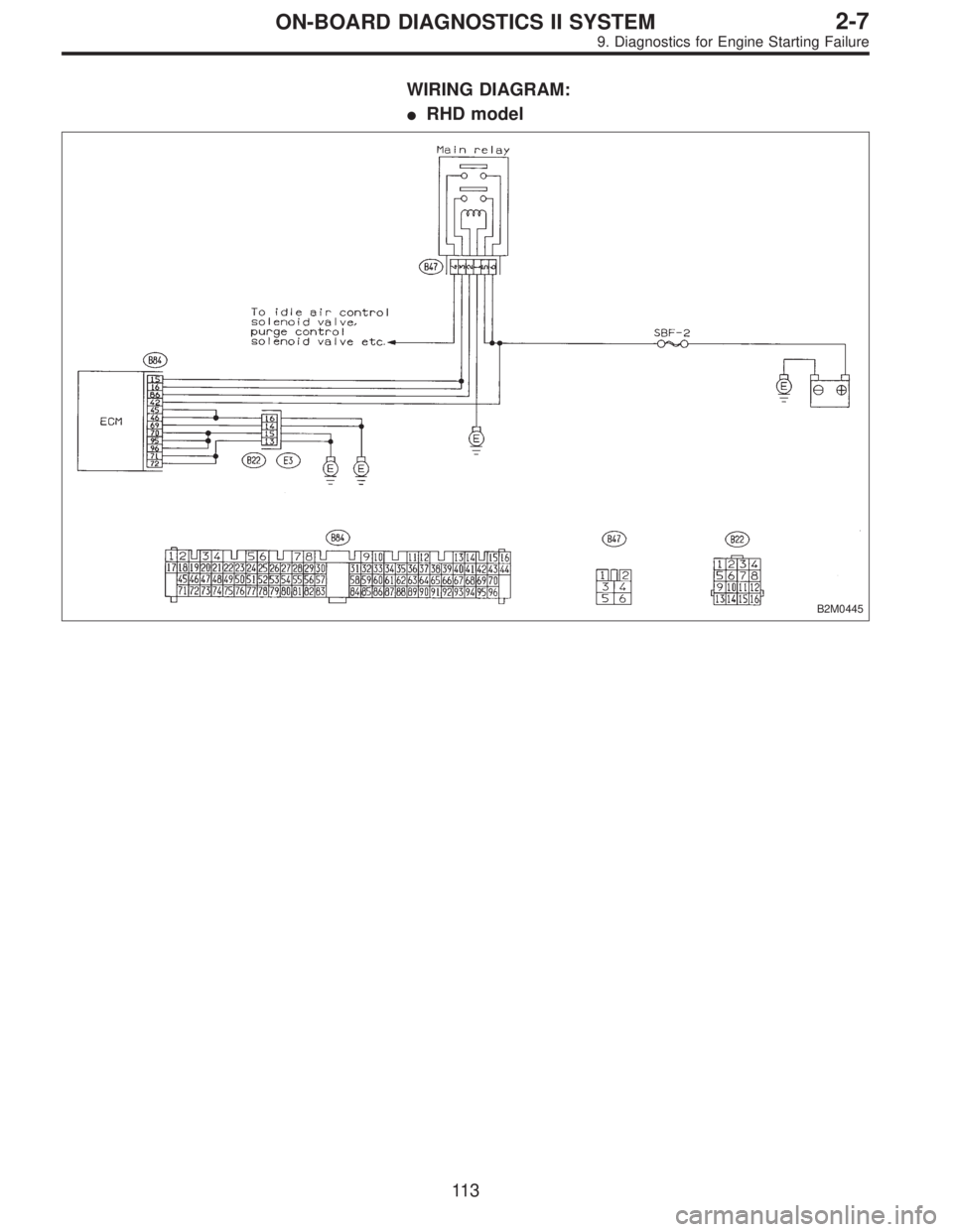
C: CONTROL MODULE POWER SUPPLY AND
GROUND LINE
1.Check main relay.
2.Check power supply circuit of ECM.
3.Check ground circuit of ECM.
CAUTION:
After repair or replacement of faulty parts, conduct
CLEAR MEMORY and INSPECTION MODES.
[T3D0] and [T3E0].>
WIRING DIAGRAM:
�LHD model
OBD0105
�
�
11 2
2-7ON-BOARD DIAGNOSTICS II SYSTEM
9. Diagnostics for Engine Starting Failure
Page 1319 of 2248
WIRING DIAGRAM:
�RHD model
B2M0445
11 3
2-7ON-BOARD DIAGNOSTICS II SYSTEM
9. Diagnostics for Engine Starting Failure
Page 1322 of 2248
D: IGNITION CONTROL SYSTEM
1.Check ignition system for sparks.
2.Check power supply circuit for ignition coil.
3.Check ignition coil.
4.Check harness connector between ignitor and
ignition coil.
5.Check input signal for ignitor.
6.Check harness connector of ignitor ground
circuit.
7.Check harness connector between ECM and
ignitor.
CAUTION:
After repair or replacement of faulty parts, conduct
CLEAR MEMORY and INSPECTION MODES.
[T3D0] and [T3E0].>
WIRING DIAGRAM:
B2M0622
�
�
�
�
�
�
11 6
2-7ON-BOARD DIAGNOSTICS II SYSTEM
9. Diagnostics for Engine Starting Failure

OBD0735
98
2-7ON-BOARD DIAGNOSTICS II SYSTEM
6. Wiring Diagram and Wiring Harness")

B2M0444
99
2-7ON-BOARD DIAGNOSTICS II SYSTEM
6. Wiring Diagram and Wiring Harness")