Page 120 of 2248
3. Engine Coolant Pipe
G2M0203
�1Engine coolant temperature sensor
�
2Engine coolant temperature gauge
�
3Engine coolant pipe
�
4O-ring
�
5By-pass hose
Tightening torque: N⋅m (kg-m, ft-lb)
T: 6.4±0.5 (0.65±0.05, 4.7±0.4)
5
2-5COMPONENT PARTS
3. Engine Coolant Pipe
Page 137 of 2248

1. Engine Cooling System
Trouble Possible cause Corrective action
Over-heatinga. Insufficient engine coolantReplenish engine coolant, inspect for leakage, and
repair.
b. Loose timing belt Repair or replace timing belt tensioner.
c. Oil on drive belt Replace.
d. Malfunction of thermostat Replace.
e. Malfunction of engine coolant pump Replace.
f. Clogged engine coolant passage Clean.
g. Improper ignition timingInspect and repair ignition control system.
h. Clogged or leaking radiator Clean or repair, or replace.
i. Improper engine oil in engine coolant Replace engine coolant.
j. Air/fuel mixture ratio too leanInspect and repair fuel injection system.
k. Excessive back pressure in exhaust system Clean or replace.
l. Insufficient clearance between piston and cylinder Adjust or replace.
m. Slipping clutch Repair or replace.
n. Dragging brake Adjust.
o. Improper transmission oil Replace.
p. Defective thermostat Replace.
q. Malfunction of electric fanInspect radiator fan relay, engine coolant temperature
sensor or radiator motor and replace there.
Over-coolinga. Atmospheric temperature extremely low Partly cover radiator front area.
b. Defective thermostat Replace.
Engine coolant
leaks.a. Loosened or damaged connecting units on hoses Repair or replace.
b. Leakage from engine coolant pump Replace.
c. Leakage from engine coolant pipe Repair or replace.
d. Leakage around cylinder head gasket Retighten cylinder head bolts or replace gasket.
e. Damaged or cracked cylinder head and crankcase Repair or replace.
f. Damaged or cracked thermostat case Repair or replace.
g. Leakage from radiator Repair or replace.
Noisea. Defective drive belt Replace.
b. Defective radiator fan Replace.
c. Defective engine coolant pump bearing Replace engine coolant pump.
d. Defective engine coolant pump mechanical seal Replace engine coolant pump.
19
2-5DIAGNOSTICS
1. Engine Cooling System
Page 161 of 2248
B2M0342
12) Disconnect brake booster hose.
B2M0343
13) Remove EGR pipe.
G2M0370
14) Disconnect canister hose from pipe.
B2M0019
15) Disconnect engine harness connectors from bulkhead
harness connectors.
B2M0345A
16) Disconnect connectors from engine coolant tempera-
ture sensor�
1and thermometer�2.
10
2-7SERVICE PROCEDURE
4. Intake Manifold
Page 165 of 2248
G2M0091
3) Connect connector to oil pressure switch.
G2M0408
4) Connect connector to crankshaft position sensor.
G2M0416
5) Connect connector to camshaft position sensor.
B2M0346
6) Connect connector to knock sensor.
B2M0345A
7) Connect connectors to engine coolant temperature sen-
sor�
1and thermometer�2.
14
2-7SERVICE PROCEDURE
4. Intake Manifold
Page 168 of 2248
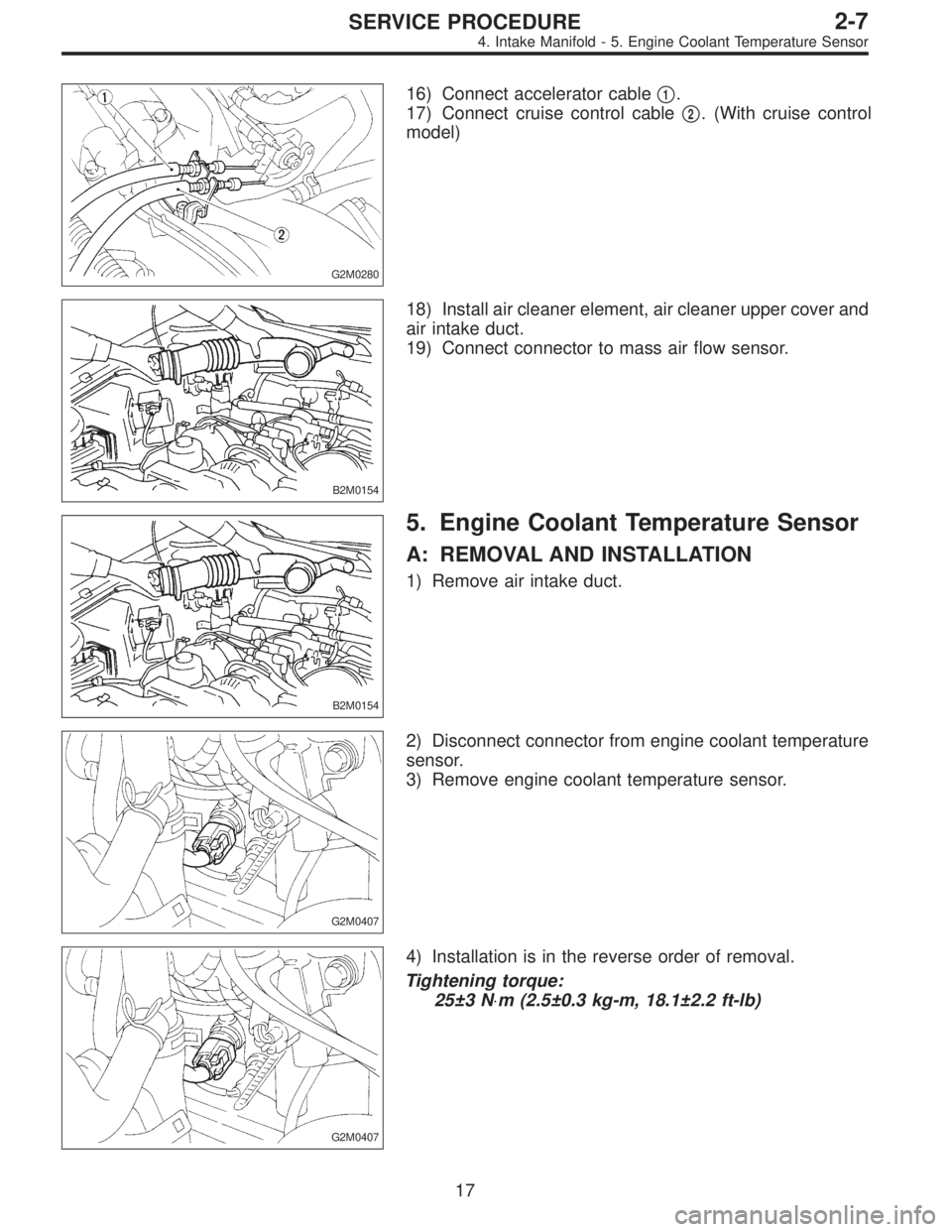
G2M0280
16) Connect accelerator cable�1.
17) Connect cruise control cable�
2. (With cruise control
model)
B2M0154
18) Install air cleaner element, air cleaner upper cover and
air intake duct.
19) Connect connector to mass air flow sensor.
B2M0154
5. Engine Coolant Temperature Sensor
A: REMOVAL AND INSTALLATION
1) Remove air intake duct.
G2M0407
2) Disconnect connector from engine coolant temperature
sensor.
3) Remove engine coolant temperature sensor.
G2M0407
4) Installation is in the reverse order of removal.
Tightening torque:
25±3 N⋅m (2.5±0.3 kg-m, 18.1±2.2 ft-lb)
17
2-7SERVICE PROCEDURE
4. Intake Manifold - 5. Engine Coolant Temperature Sensor
Page 169 of 2248
G2M0280
16) Connect accelerator cable�1.
17) Connect cruise control cable�
2. (With cruise control
model)
B2M0154
18) Install air cleaner element, air cleaner upper cover and
air intake duct.
19) Connect connector to mass air flow sensor.
B2M0154
5. Engine Coolant Temperature Sensor
A: REMOVAL AND INSTALLATION
1) Remove air intake duct.
G2M0407
2) Disconnect connector from engine coolant temperature
sensor.
3) Remove engine coolant temperature sensor.
G2M0407
4) Installation is in the reverse order of removal.
Tightening torque:
25±3 N⋅m (2.5±0.3 kg-m, 18.1±2.2 ft-lb)
17
2-7SERVICE PROCEDURE
4. Intake Manifold - 5. Engine Coolant Temperature Sensor
Page 374 of 2248
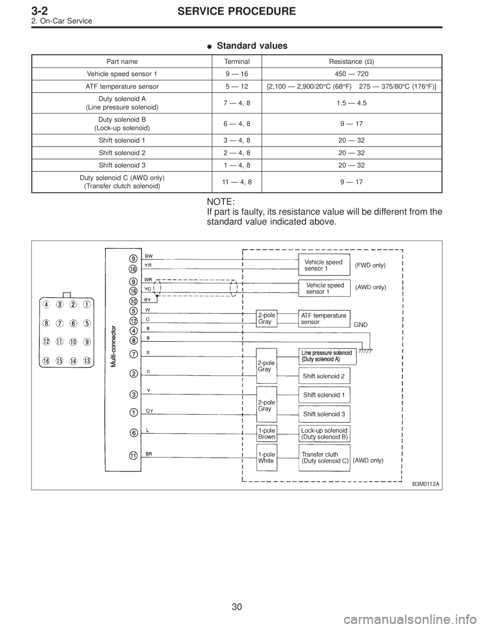
�Standard values
Part name Terminal Resistance (Ω)
Vehicle speed sensor 1 9—16 450—720
ATF temperature sensor 5—12 [2,100—2,900/20°C (68°F) 275—375/80°C (176°F)]
Duty solenoid A
(Line pressure solenoid)7—4, 8 1.5—4.5
Duty solenoid B
(Lock-up solenoid)6—4, 8 9—17
Shift solenoid 1 3—4, 8 20—32
Shift solenoid 2 2—4, 8 20—32
Shift solenoid 3 1—4, 8 20—32
Duty solenoid C (AWD only)
(Transfer clutch solenoid)11—4, 8 9—17
NOTE:
If part is faulty, its resistance value will be different from the
standard value indicated above.
B3M0112A
30
3-2SERVICE PROCEDURE
2. On-Car Service
Page 419 of 2248
G3M0367
2) Install and route the transmission harness.
CAUTION:
Be careful not to damage the harness.
B3M0418A
3) Install the control valve assembly.
(1) Set the select lever in range“2”.
(2) Install the two brackets, ATF temperature sensor
and the control valve by engaging the manual valve and
manual lever, then tighten the 17 bolts.
Tightening torque:
8±1 N⋅m (0.8±0.1 kg-m, 5.8±0.7 ft-lb)
CAUTION:
�Be careful not to pinch the harness roll the gasket.
�Tighten the control valve mounting bolts evenly.
B3M0419A
4) Install the oil strainer to the control valve. Be careful not
to cut or break the O-ring. Then tighten four bolts.
Tightening torque:
8±1 N⋅m (0.8±0.1 kg-m, 5.8±0.7 ft-lb)
B3M0420A
5) Secure four connectors.
75
3-2SERVICE PROCEDURE
4. Overall Transmission

 Disconnect brake booster hose.
B2M0343
13) Remove EGR pipe.
G2M0370
14) Disconnect canister hose from pipe.
B2M0019
15) Disconnect engine harness connectors from bulkhead
harness connector")
 Connect connector to oil pressure switch.
G2M0408
4) Connect connector to crankshaft position sensor.
G2M0416
5) Connect connector to camshaft position sensor.
B2M0346
6) Connect connector")

 Install and route the transmission harness.
CAUTION:
Be careful not to damage the harness.
B3M0418A
3) Install the control valve assembly.
(1) Set the select lever in range“2”.
(2) Inst")