Page 402 of 2248
G3M0371
5) Remove the snap ring. Then remove the speedometer
driven gear.
G3M0372
6) Remove vehicle speed sensor 2.
7) Tap out the speedometer shaft to the outside of the
case, and remove the oil seal.
G3M0373
5. EXTENSION SECTION
1) Take out the transfer clutch by lightly tapping the end of
the rear drive shaft.
CAUTION:
Be careful not to damage the oil seal in the extension.
G3M0867
2) Remove duty solenoid C, transfer valve body and the
transfer pipe.
CAUTION:
�Take out the inlet filter.
�Do not damage the O-ring.
�Be careful not to bend the pipe.
B3M0831A
3) Take out the roller bearing inner race with ST.
ST 398527700 PULLER
4) Take out the roller bearing outer race with ST.
NOTE:
Hook ST in the inner side of the roller bearing outer race.
ST 398527700 PULLER
58
3-2SERVICE PROCEDURE
4. Overall Transmission
Page 420 of 2248

G3M0345
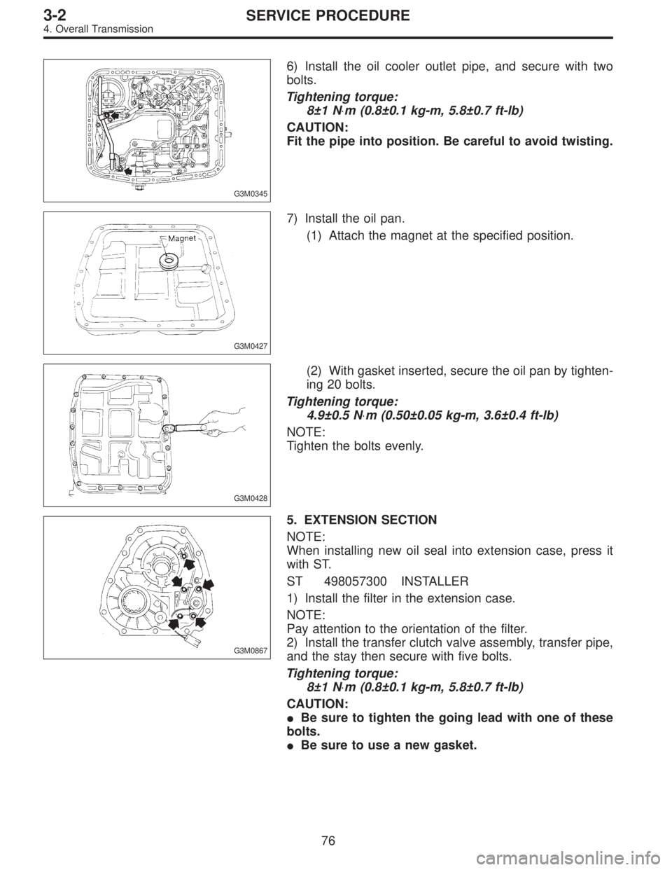
6) Install the oil cooler outlet pipe, and secure with two
bolts.
Tightening torque:
8±1 N⋅m (0.8±0.1 kg-m, 5.8±0.7 ft-lb)
CAUTION:
Fit the pipe into position. Be careful to avoid twisting.
G3M0427
7) Install the oil pan.
(1) Attach the magnet at the specified position.
G3M0428
(2) With gasket inserted, secure the oil pan by tighten-
ing 20 bolts.
Tightening torque:
4.9±0.5 N⋅m (0.50±0.05 kg-m, 3.6±0.4 ft-lb)
NOTE:
Tighten the bolts evenly.
G3M0867
5. EXTENSION SECTION
NOTE:
When installing new oil seal into extension case, press it
with ST.
ST 498057300 INSTALLER
1) Install the filter in the extension case.
NOTE:
Pay attention to the orientation of the filter.
2) Install the transfer clutch valve assembly, transfer pipe,
and the stay then secure with five bolts.
Tightening torque:
8±1 N⋅m (0.8±0.1 kg-m, 5.8±0.7 ft-lb)
CAUTION:
�Be sure to tighten the going lead with one of these
bolts.
�Be sure to use a new gasket.
76
3-2SERVICE PROCEDURE
4. Overall Transmission
Page 433 of 2248
G3M0906
5) Temporarily assemble lower valve body to upper valve
body.
CAUTION:
Be careful not to drop the upper body interior steel
ball, or the lower body interior filter, orifice check
spring, or orifice check valve.
B3M0406A
6) Install the duty solenoid B and the four brackets.
7) Tighten twenty seven bolts & washers and two reamer
bolts.
Tightening torque:
T1: 8±1 N⋅m (0.8±0.1 kg-m, 5.8±0.7 ft-lb)
T2: 11.3±1.5 N⋅m (1.15±0.15 kg-m, 8.3±1.1 ft-lb)
Unit: mm (in)
abcde
Length 70 (2.76) 50 (1.97) 33 (1.30) 27 (1.06) 28 (1.10)
Numbers 2 6 16 1 2
G3M0864
8) Install the shift solenoid and duty solenoid A.
a length : 16 mm (0.63 in)
b length : 27 mm (1.06 in)
Tightening torque:
8±1 N⋅m (0.8±0.1 kg-m, 5.8±0.7 ft-lb)
G3M0445
7. Oil Pump Assembly
A: DISASSEMBLY
1) Remove the oil seal retainer.
Also remove the O-ring and oil seal (air breather).
89
3-2SERVICE PROCEDURE
6. Control Valve Body - 7. Oil Pump Assembly
Page 434 of 2248
G3M0906
5) Temporarily assemble lower valve body to upper valve
body.
CAUTION:
Be careful not to drop the upper body interior steel
ball, or the lower body interior filter, orifice check
spring, or orifice check valve.
B3M0406A
6) Install the duty solenoid B and the four brackets.
7) Tighten twenty seven bolts & washers and two reamer
bolts.
Tightening torque:
T1: 8±1 N⋅m (0.8±0.1 kg-m, 5.8±0.7 ft-lb)
T2: 11.3±1.5 N⋅m (1.15±0.15 kg-m, 8.3±1.1 ft-lb)
Unit: mm (in)
abcde
Length 70 (2.76) 50 (1.97) 33 (1.30) 27 (1.06) 28 (1.10)
Numbers 2 6 16 1 2
G3M0864
8) Install the shift solenoid and duty solenoid A.
a length : 16 mm (0.63 in)
b length : 27 mm (1.06 in)
Tightening torque:
8±1 N⋅m (0.8±0.1 kg-m, 5.8±0.7 ft-lb)
G3M0445
7. Oil Pump Assembly
A: DISASSEMBLY
1) Remove the oil seal retainer.
Also remove the O-ring and oil seal (air breather).
89
3-2SERVICE PROCEDURE
6. Control Valve Body - 7. Oil Pump Assembly
Page 883 of 2248

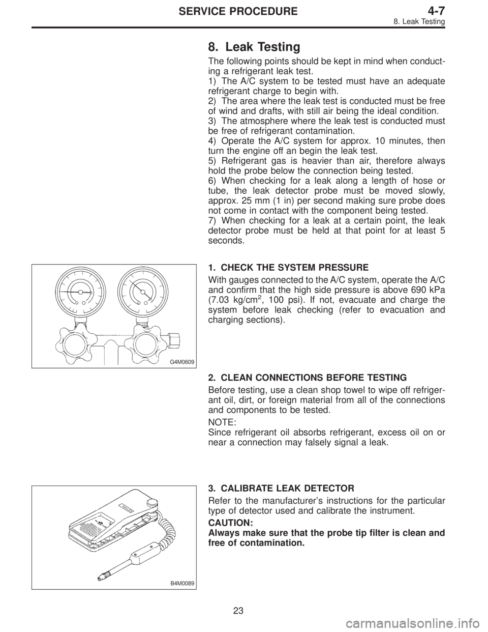
8. Leak Testing
The following points should be kept in mind when conduct-
ing a refrigerant leak test.
1) The A/C system to be tested must have an adequate
refrigerant charge to begin with.
2) The area where the leak test is conducted must be free
of wind and drafts, with still air being the ideal condition.
3) The atmosphere where the leak test is conducted must
be free of refrigerant contamination.
4) Operate the A/C system for approx. 10 minutes, then
turn the engine off an begin the leak test.
5) Refrigerant gas is heavier than air, therefore always
hold the probe below the connection being tested.
6) When checking for a leak along a length of hose or
tube, the leak detector probe must be moved slowly,
approx. 25 mm (1 in) per second making sure probe does
not come in contact with the component being tested.
7) When checking for a leak at a certain point, the leak
detector probe must be held at that point for at least 5
seconds.
G4M0609
1. CHECK THE SYSTEM PRESSURE
With gauges connected to the A/C system, operate the A/C
and confirm that the high side pressure is above 690 kPa
(7.03 kg/cm
2, 100 psi). If not, evacuate and charge the
system before leak checking (refer to evacuation and
charging sections).
2. CLEAN CONNECTIONS BEFORE TESTING
Before testing, use a clean shop towel to wipe off refriger-
ant oil, dirt, or foreign material from all of the connections
and components to be tested.
NOTE:
Since refrigerant oil absorbs refrigerant, excess oil on or
near a connection may falsely signal a leak.
B4M0089
3. CALIBRATE LEAK DETECTOR
Refer to the manufacturer’s instructions for the particular
type of detector used and calibrate the instrument.
CAUTION:
Always make sure that the probe tip filter is clean and
free of contamination.
23
4-7SERVICE PROCEDURE
8. Leak Testing
Page 1211 of 2248

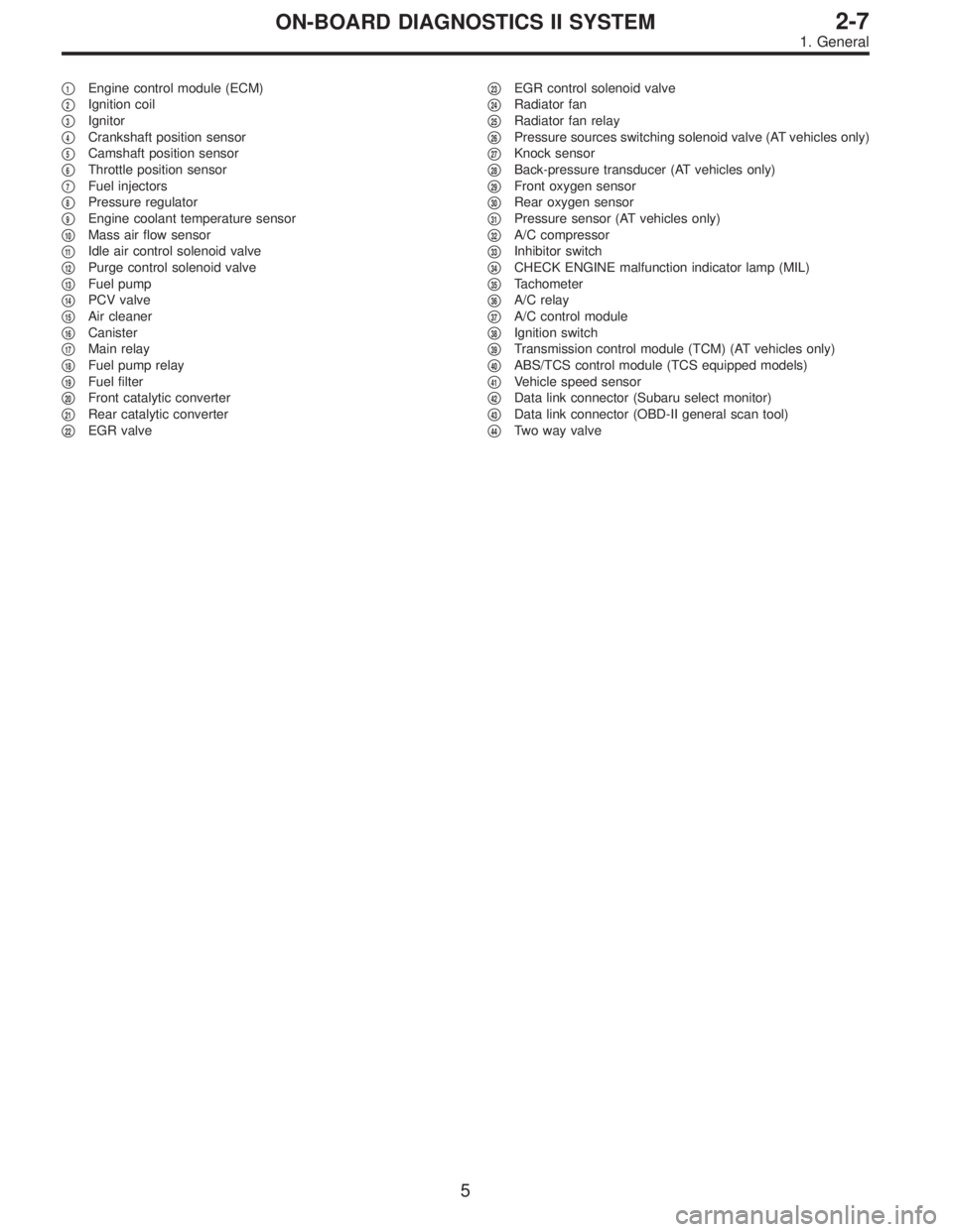
�1Engine control module (ECM)
�
2Ignition coil
�
3Ignitor
�
4Crankshaft position sensor
�
5Camshaft position sensor
�
6Throttle position sensor
�
7Fuel injectors
�
8Pressure regulator
�
9Engine coolant temperature sensor
�
10Mass air flow sensor
�
11Idle air control solenoid valve
�
12Purge control solenoid valve
�
13Fuel pump
�
14PCV valve
�
15Air cleaner
�
16Canister
�
17Main relay
�
18Fuel pump relay
�
19Fuel filter
�
20Front catalytic converter
�
21Rear catalytic converter
�
22EGR valve�
23EGR control solenoid valve
�
24Radiator fan
�
25Radiator fan relay
�
26Pressure sources switching solenoid valve (AT vehicles only)
�
27Knock sensor
�
28Back-pressure transducer (AT vehicles only)
�
29Front oxygen sensor
�
30Rear oxygen sensor
�
31Pressure sensor (AT vehicles only)
�
32A/C compressor
�
33Inhibitor switch
�
34CHECK ENGINE malfunction indicator lamp (MIL)
�
35Tachometer
�
36A/C relay
�
37A/C control module
�
38Ignition switch
�
39Transmission control module (TCM) (AT vehicles only)
�
40ABS/TCS control module (TCS equipped models)
�
41Vehicle speed sensor
�
42Data link connector (Subaru select monitor)
�
43Data link connector (OBD-II general scan tool)
�
44Two way valve
5
2-7ON-BOARD DIAGNOSTICS II SYSTEM
1. General
Page 1334 of 2248

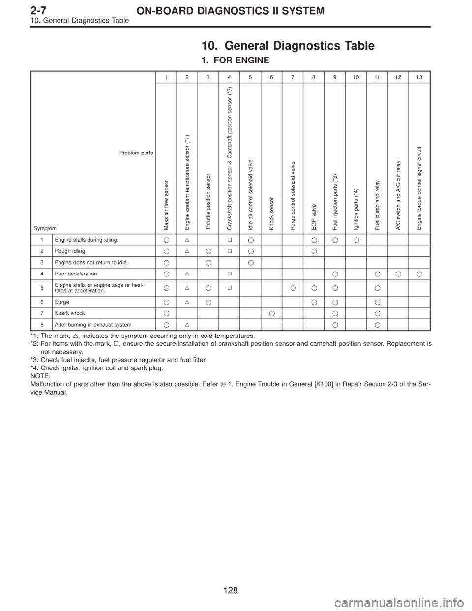
10. General Diagnostics Table
1. FOR ENGINE
12345678910111213
Problem parts
Mass air flow sensor
Engine coolant temperature sensor (*1)
Throttle position sensor
Crankshaft position sensor & Camshaft position sensor (*2)
Idle air control solenoid valve
Knock sensor
Purge control solenoid valve
EGR valve
Fuel injection parts (*3)
Ignition parts (*4)
Fuel pump and relay
A/C switch and A/C cut relay
Engine torque control signal circuitSymptom
1 Engine stalls during idling.�� � � ���
2 Rough idling�� � � � �
3 Engine does not return to idle.���
4 Poor acceleration�� � � ���
5Engine stalls or engine sags or hesi-
tates at acceleration.�� � � ��� �
6 Surge�� � �� �
7 Spark knock����
8 After burning in exhaust system�� � �
*1: The mark,�, indicates the symptom occurring only in cold temperatures.
*2: For items with the mark,�, ensure the secure installation of crankshaft position sensor and camshaft position sensor. Replacement is
not necessary.
*3: Check fuel injector, fuel pressure regulator and fuel filter.
*4: Check igniter, ignition coil and spark plug.
NOTE:
Malfunction of parts other than the above is also possible. Refer to 1. Engine Trouble in General [K100] in Repair Section 2-3 of the Ser-
vice Manual.
128
2-7ON-BOARD DIAGNOSTICS II SYSTEM
10. General Diagnostics Table