Page 1426 of 2248
 Disconnect connector from knock sensor.
2) Measure resistance of harness between knock sensor
connector and body.
: Connector & terminal
(E14) No. 1—Body/400 kΩ,")
OBD0717A
3
CHECK KNOCK SENSOR.
1) Disconnect connector from knock sensor.
2) Measure resistance of harness between knock sensor
connector and body.
: Connector & terminal
(E14) No. 1—Body/400 kΩ, or less
: Replace knock sensor.
: Repair short circuit of harness between knock
sensor connector and ECM connector.
NOTE:
The harness between both connectors is shielded. Repair
short circuit of harness together with shield.
B2M0625A
4
CHECK INPUT SIGNAL FOR ECM.
1) Connect connectors to ECM and knock sensor.
2) Turn ignition switch to ON.
3) Measure voltage between ECM and body.
: Connector & terminal
(B84) No. 30—Body/2 V, or more
: Repair poor contact in ECM connector.
: Even if MIL lights up, the circuit has returned to a
normal condition at this time. (However, the pos-
sibility of poor contact still remains.)
Check and repair the following connectors.
�Knock sensor connector
�ECM connector
�Coupling connector (B21)
220
2-7ON-BOARD DIAGNOSTICS II SYSTEM
11. Diagnostics Chart with Trouble Code
Page 1428 of 2248
DTC DETECTING CONDITION:
�Immediately at fault recognition
TROUBLE SYMPTOM:
�Engine stalls.
�Failure of engine to start
1.Check harness.
2.Check crankshaft position sensor.
CAUTION:
After repair or replacement of faulty parts, conduct
CLEAR MEMORY and INSPECTION MODES.
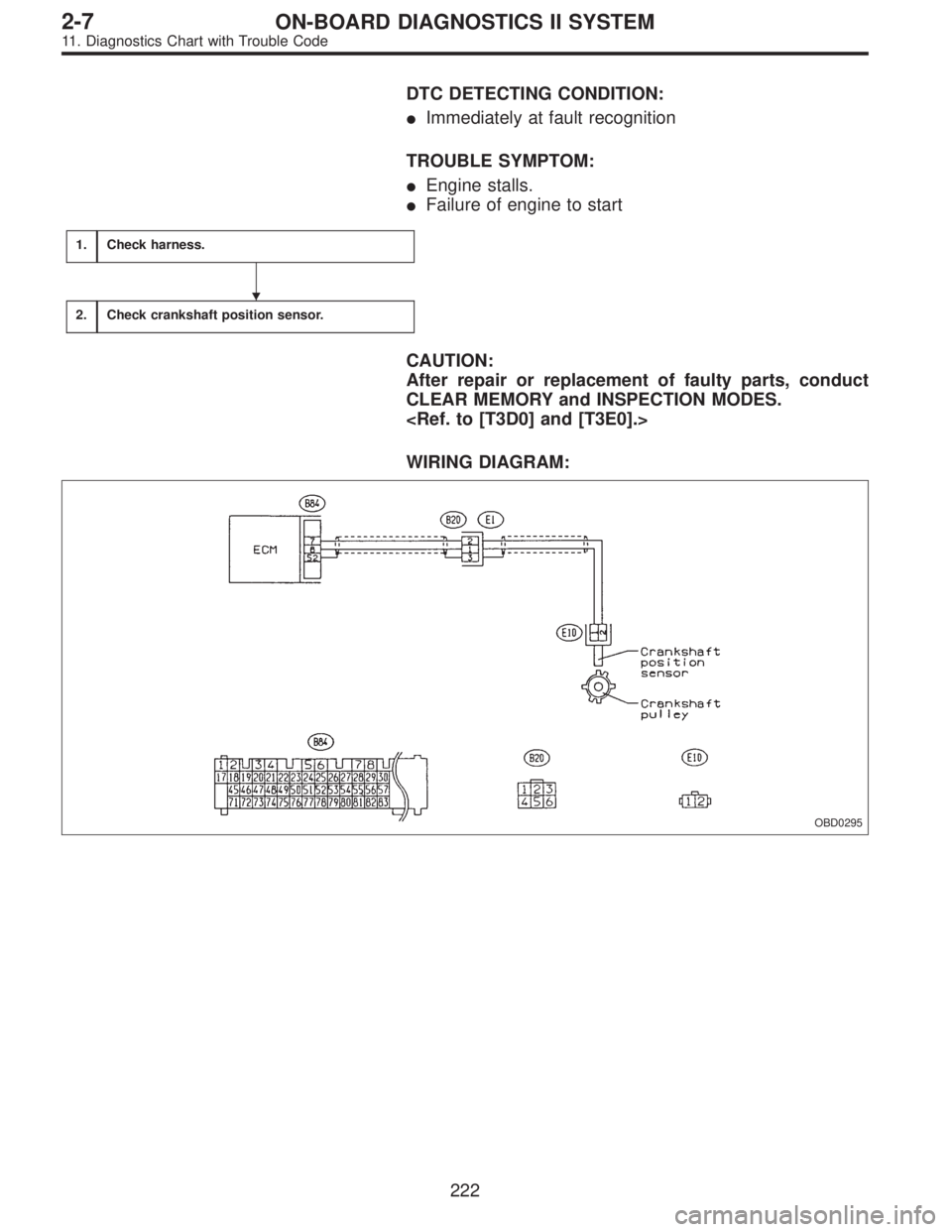
WIRING DIAGRAM:
OBD0295
�
222
2-7ON-BOARD DIAGNOSTICS II SYSTEM
11. Diagnostics Chart with Trouble Code
Page 1441 of 2248
OBD0323
AC: DTC P0403
—EXHAUST GAS RECIRCULATION CIRCUIT
MALFUNCTION (EGRSOL)—
OBD0324A
DESCRIPTION:
The EGR solenoid valve is situated between the BPT and
EGR valve. EGR solenoid valve is opened by a signal
emitted from the ECM. Therefore, throttle port pressure is
transmitted to diaphragm of EGR valve.
DTC DETECTING CONDITION:
�Two consecutive trips with fault
TROUBLE SYMPTOM:
�Poor driving performance on low engine speed
1.Check transmission type.
AT
�MT
Check AT/MT identification circuit.
2.Check output signal from ECM.
�
3.Check harness.
4.Check harness.
5.Check EGR solenoid valve.
6.Check power supply to EGR solenoid valve.
CAUTION:
After repair or replacement of faulty parts, conduct
CLEAR MEMORY and INSPECTION MODES.
[T3D0] and [T3E0].>
�
�
�
�
235
2-7ON-BOARD DIAGNOSTICS II SYSTEM
11. Diagnostics Chart with Trouble Code
Page 1451 of 2248
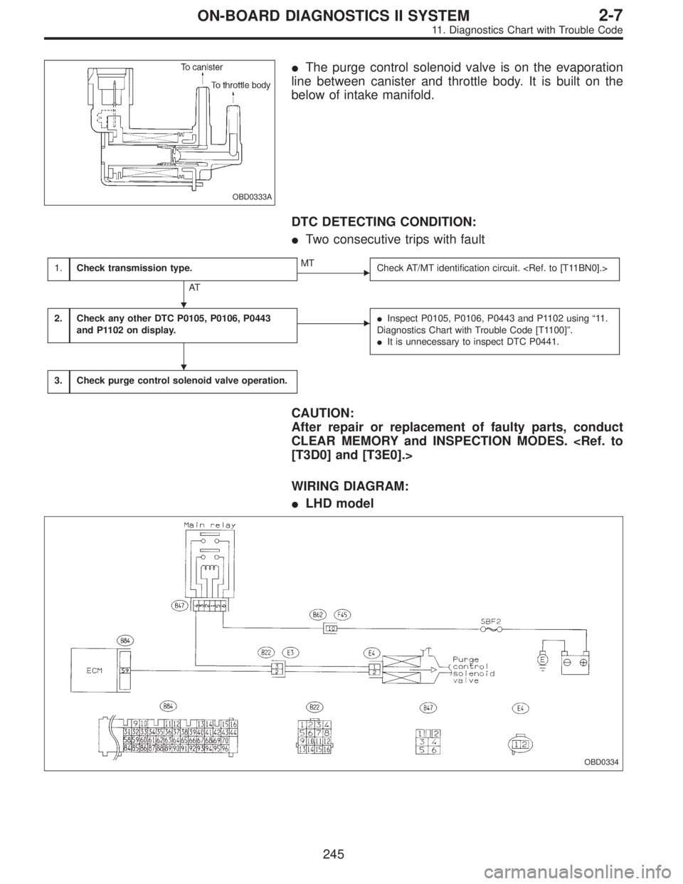
OBD0333A
�The purge control solenoid valve is on the evaporation
line between canister and throttle body. It is built on the
below of intake manifold.
DTC DETECTING CONDITION:
�Two consecutive trips with fault
1.Check transmission type.
AT
�MT
Check AT/MT identification circuit.
2.Check any other DTC P0105, P0106, P0443
and P1102 on display.��Inspect P0105, P0106, P0443 and P1102 using“11 .
Diagnostics Chart with Trouble Code [T1100]”.
�It is unnecessary to inspect DTC P0441.
3.Check purge control solenoid valve operation.
CAUTION:
After repair or replacement of faulty parts, conduct
CLEAR MEMORY and INSPECTION MODES.
[T3D0] and [T3E0].>
WIRING DIAGRAM:
�LHD model
OBD0334
�
�
245
2-7ON-BOARD DIAGNOSTICS II SYSTEM
11. Diagnostics Chart with Trouble Code
Page 1454 of 2248
OBD0335
AF: DTC P0443
—EVAPORATIVE EMISSION CONTROL
SYSTEM PURGE CONTROL VALVE CIRCUIT
MALFUNCTION (CPC)—
DESCRIPTION:
Refer to“AE: DTC P0441—EVAPORATIVE EMISSION
CONTROL SYSTEM INCORRECT PURGE FLOW—
[T11AE0]”.
DTC DETECTING CONDITION:
�Two consecutive trips with fault
TROUBLE SYMPTOM:
�Erroneous idling
1.Check output signal from ECM.
�
2.Check harness.
3.Check harness.
4.Check purge control solenoid valve.
5.Check power supply to purge control solenoid
valve.
CAUTION:
After repair or replacement of faulty parts, conduct
CLEAR MEMORY and INSPECTION MODES.
[T3D0] and [T3E0].>
�
�
�
248
2-7ON-BOARD DIAGNOSTICS II SYSTEM
11. Diagnostics Chart with Trouble Code
Page 1462 of 2248
OBD0358
OBD0688A
AH: DTC P0505
—IDLE CONTROL SYSTEM MALFUNCTION
(ISC)—
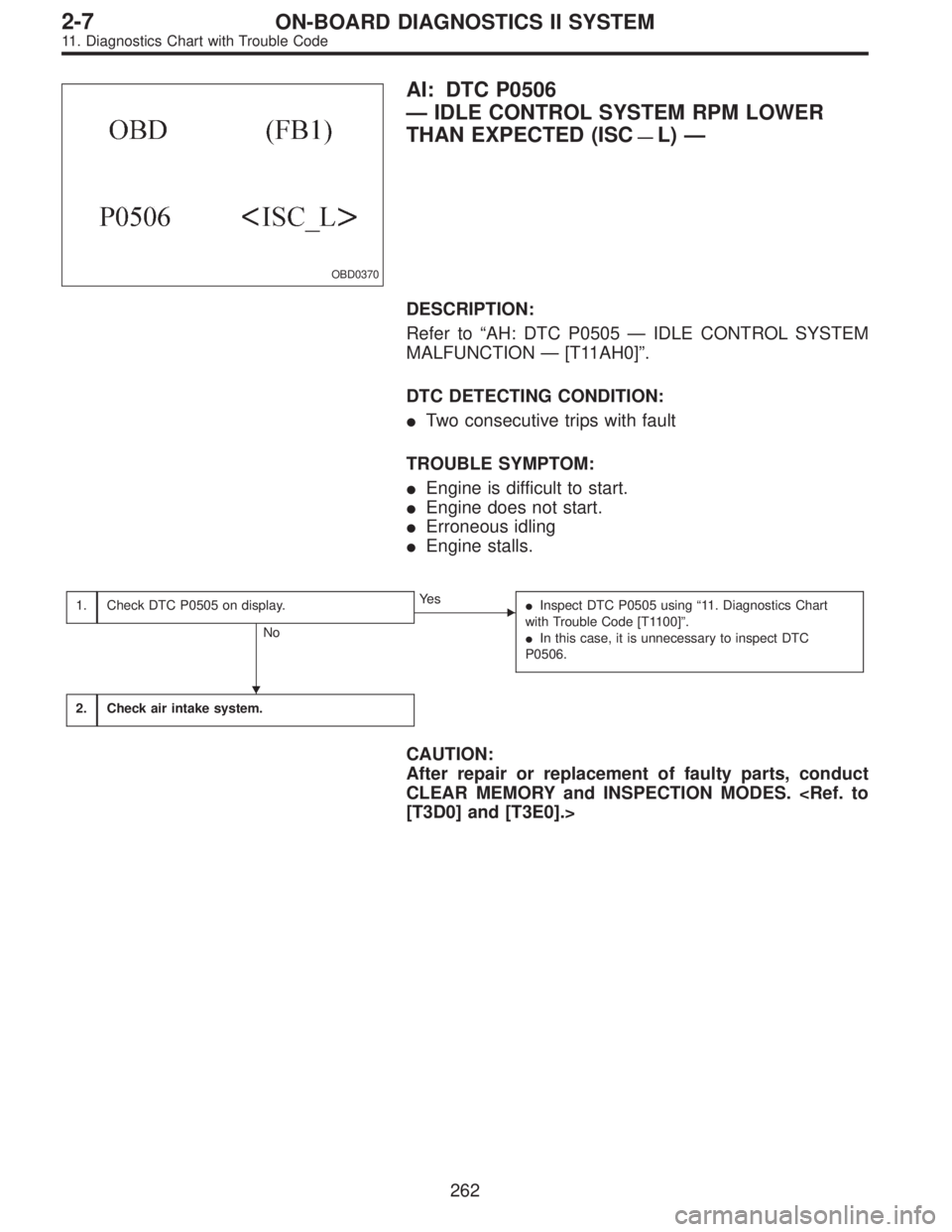
DESCRIPTION:
�Idle air control solenoid valve consists of an air cut valve,
duty control valve, intake air passage and a coolant pas-
sage.
�Air cut valve contains a bimetallic substance which
responds to coolant temperature, and a duty control valve
which is operated by a signal sent from ECM.
�When engine coolant temperature is low, air cut valve is
fully opened by the action of the bimetallic substance so
that the air flow required for low engine coolant tempera-
tures is maintained.
�ECM controls duty control valve to bring the operating
engine speed as close to preset idle speed as possible.
DTC DETECTING CONDITION:
�Immediately at fault recognition
TROUBLE SYMPTOM:
�Erroneous idling
�Engine stalls.
�Engine breathing
256
2-7ON-BOARD DIAGNOSTICS II SYSTEM
11. Diagnostics Chart with Trouble Code
Page 1467 of 2248
 Turn ignition switch to OFF.
2) Disconnect connector from idle air control solenoid
valve.
3) Turn ignition switch to ON.
4) Measu")
B2M0253A
4CHECK POWER SUPPLY TO IDLE AIR CON-
TROL SOLENOID VALVE.
1) Turn ignition switch to OFF.
2) Disconnect connector from idle air control solenoid
valve.
3) Turn ignition switch to ON.
4) Measure voltage between idle air control solenoid valve
and body.
: Connector & terminal
(E7) No. 2—Body / 10 V, or more
: Go to step 5.
: Repair open circuit of harness between idle air
control solenoid valve connector and ECM con-
nector.
OBD0368A
5CHECK HARNESS CONNECTOR BETWEEN
ECM AND IDLE AIR CONTROL SOLENOID
VA LV E .
1) Turn ignition switch to OFF.
2) Disconnect connector from ECM.
3) Measure resistance of harness connector between
ECM and idle air control solenoid valve.
: Connector & terminal
(B84) No. 11—(E7) No. 3 / 10Ω, or less
(B84) No. 12—(E7) No. 1 / 10Ω, or less
: Repair open circuit of harness between ECM con-
nector and idle air control solenoid valve connec-
tor.
: Go to the next step.
OBD0369A
4) Measure resistance of harness connector between
ECM and body to make sure that circuit does not short.
: Connector & terminal
(B84) No. 11—Body / 1 MΩ, or more
(B84) No. 12—Body / 1 MΩ, or more
: Confirm good condition in connectors of idle air
control solenoid valve circuit.
: Repair short circuit of harness between ECM con-
nector and idle air control solenoid valve connec-
tor.
261
2-7ON-BOARD DIAGNOSTICS II SYSTEM
11. Diagnostics Chart with Trouble Code
Page 1468 of 2248
OBD0370
AI: DTC P0506
—IDLE CONTROL SYSTEM RPM LOWER
THAN EXPECTED (ISC
—L)—
DESCRIPTION:
Refer to“AH: DTC P0505—IDLE CONTROL SYSTEM
MALFUNCTION—[T11AH0]”.
DTC DETECTING CONDITION:
�Two consecutive trips with fault
TROUBLE SYMPTOM:
�Engine is difficult to start.
�Engine does not start.
�Erroneous idling
�Engine stalls.
1.Check DTC P0505 on display.
No
�Ye s
�Inspect DTC P0505 using“11. Diagnostics Chart
with Trouble Code [T1100]”.
�In this case, it is unnecessary to inspect DTC
P0506.
2.Check air intake system.
CAUTION:
After repair or replacement of faulty parts, conduct
CLEAR MEMORY and INSPECTION MODES.
[T3D0] and [T3E0].>
�
262
2-7ON-BOARD DIAGNOSTICS II SYSTEM
11. Diagnostics Chart with Trouble Code
—
OBD0324A
DESCRIPTION:
The EGR solenoid valve is situated between the BPT and
EGR valve. EGR solenoid valve is opened")
—
DESCRIPTION:
Refer to“AE: DTC P0441—EVAPORATIVE EMISSION
CONTROL SYSTEM INCORRECT PURG")