Page 1531 of 2248
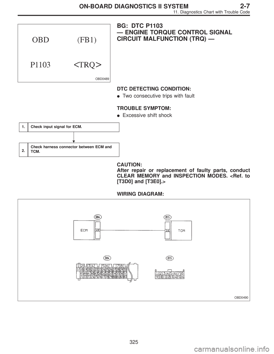
OBD0489
BG: DTC P1103
—ENGINE TORQUE CONTROL SIGNAL
CIRCUIT MALFUNCTION (TRQ)—
DTC DETECTING CONDITION:
�Two consecutive trips with fault
TROUBLE SYMPTOM:
�Excessive shift shock
1.Check input signal for ECM.
2.Check harness connector between ECM and
TCM.
CAUTION:
After repair or replacement of faulty parts, conduct
CLEAR MEMORY and INSPECTION MODES.
[T3D0] and [T3E0].>
WIRING DIAGRAM:
OBD0490
�
325
2-7ON-BOARD DIAGNOSTICS II SYSTEM
11. Diagnostics Chart with Trouble Code
Page 1534 of 2248
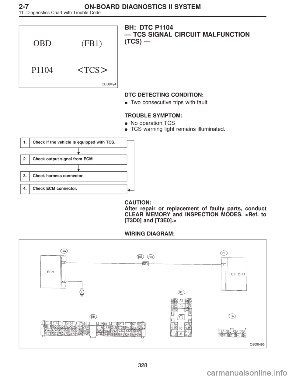
OBD0494
BH: DTC P1104
—TCS SIGNAL CIRCUIT MALFUNCTION
(TCS)—
DTC DETECTING CONDITION:
�Two consecutive trips with fault
TROUBLE SYMPTOM:
�No operation TCS
�TCS warning light remains illuminated.
1.Check if the vehicle is equipped with TCS.
�
2.Check output signal from ECM.
3.Check harness connector.
4.Check ECM connector.
CAUTION:
After repair or replacement of faulty parts, conduct
CLEAR MEMORY and INSPECTION MODES.
[T3D0] and [T3E0].>
WIRING DIAGRAM:
OBD0495
�
�
328
2-7ON-BOARD DIAGNOSTICS II SYSTEM
11. Diagnostics Chart with Trouble Code
Page 1537 of 2248
—
DESCRIPTION:
�The engine cooling system consists of a down-flow
radiator which features high heat-dissipation performanc")
OBD0527
BI: DTC P1500
—RADIATOR FAN RELAY 1 CIRCUIT
MALFUNCTION (FAN
—1)—
DESCRIPTION:
�The engine cooling system consists of a down-flow
radiator which features high heat-dissipation performance,
an electric motor fan, an engine coolant pump, a
thermostat, and an engine coolant temperature sensor.
�The ON-OFF control of the radiator fan is governed by
the ECM which receives signals sent from the engine cool-
ant temperature sensor. On models which are equipped
with an air conditioning system, the ECM receives signals
sent from the engine coolant temperature sensor, vehicle
speed sensor 2 and A/C switch. These signals simulta-
neously turn ON or OFF the radiator main fan and radiator
sub fan as well as setting them at“HI”or“LO”speed.
[Without A/C models]
Engine coolant temperature signal *1ECM output signal Operation of radiator fan
Radiator fan relay 1 Main
ON ON ON
OFF OFF OFF
*1 ON: Above 95°C (203°F), OFF: Below 89°C (192°F)
[With A/C models]
Engine coolant
temperature
signal *2A/C compressorVehicle speed
signal *3ECM output signal Operation of radiator fan
Radiator fan
relay 1Radiator fan
relay 2Main Sub
ONONON ON ON HI HI
OFF ON ON HI HI
OFFON ON ON HI HI
OFF ON OFF LO LO
OFFONON ON ON HI HI
OFF ON OFF LO LO
OFFON OFF OFF OFF OFF
OFF OFF OFF OFF OFF
*2 ON: Above 95°C (203°F), OFF: Below 89°C (192°F)
*3 ON: Above 20 km/h (12 MPH), OFF: Below 10 km/h (6 MPH)
331
2-7ON-BOARD DIAGNOSTICS II SYSTEM
11. Diagnostics Chart with Trouble Code
Page 1538 of 2248
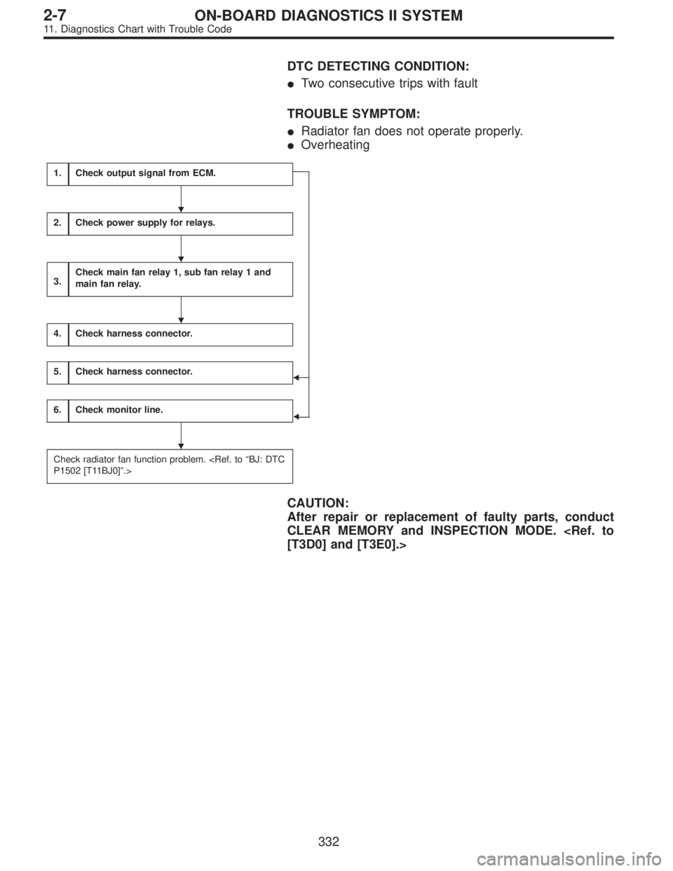
DTC DETECTING CONDITION:
�Two consecutive trips with fault
TROUBLE SYMPTOM:
�Radiator fan does not operate properly.
�Overheating
1.Check output signal from ECM.
�
�
2.Check power supply for relays.
3.Check main fan relay 1, sub fan relay 1 and
main fan relay.
4.Check harness connector.
5.Check harness connector.
6.Check monitor line.
Check radiator fan function problem.
P1502 [T11BJ0]”.>
CAUTION:
After repair or replacement of faulty parts, conduct
CLEAR MEMORY and INSPECTION MODE.
[T3D0] and [T3E0].>
�
�
�
�
332
2-7ON-BOARD DIAGNOSTICS II SYSTEM
11. Diagnostics Chart with Trouble Code
Page 1549 of 2248
OBD0511
BL: DTC P1701
—CRUISE CONTROL SET SIGNAL CIRCUIT
MALFUNCTION FOR AUTOMATIC
TRANSMISSION (CRS)—
DESCRIPTION:
Detects operation of cruise control, and expands“4th”
operating range.
DTC DETECTING CONDITION:
�Two consecutive trips with fault
1.Check harness connector between TCM and
CCM.
2.Check input signal for TCM.
CAUTION:
After repair or replacement of faulty parts, conduct
CLEAR MEMORY and INSPECTION MODES.
[T3D0] and [T3E0].>
�
343
2-7ON-BOARD DIAGNOSTICS II SYSTEM
11. Diagnostics Chart with Trouble Code
Page 1552 of 2248
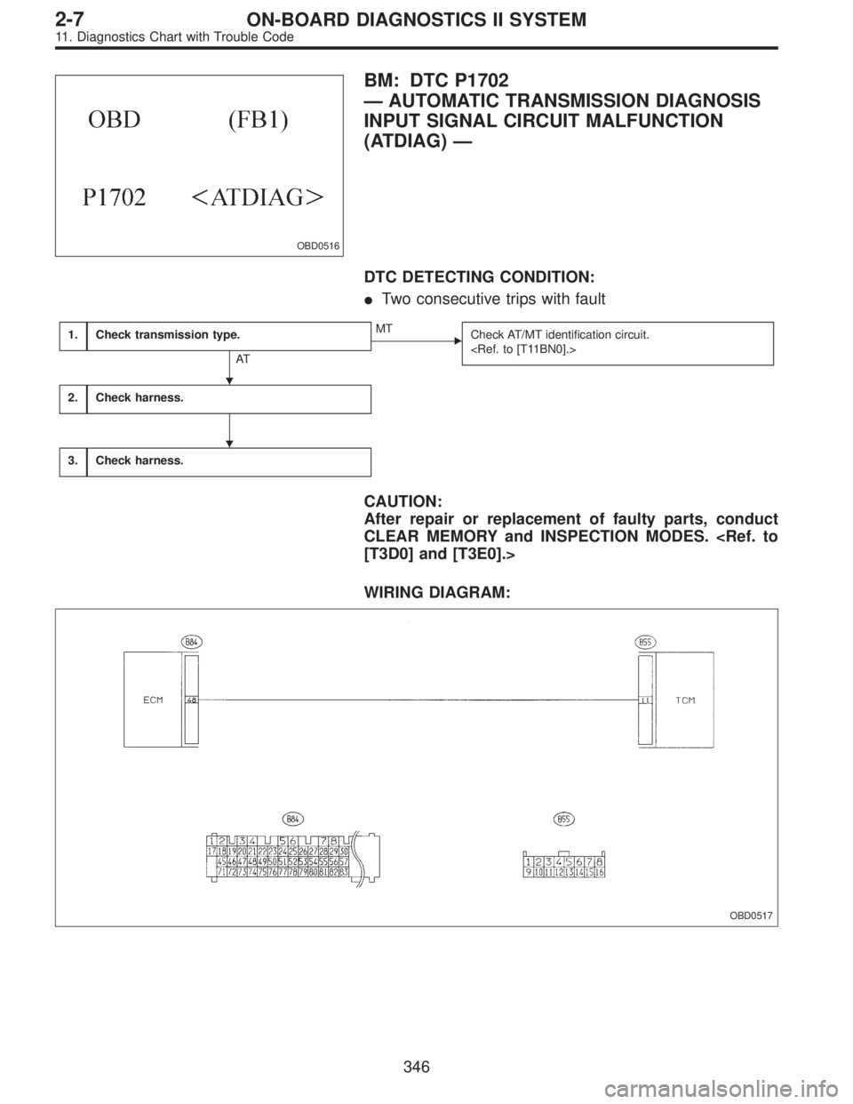
OBD0516
BM: DTC P1702
—AUTOMATIC TRANSMISSION DIAGNOSIS
INPUT SIGNAL CIRCUIT MALFUNCTION
(ATDIAG)—
DTC DETECTING CONDITION:
�Two consecutive trips with fault
1.Check transmission type.
AT
�MT
Check AT/MT identification circuit.
2.Check harness.
3.Check harness.
CAUTION:
After repair or replacement of faulty parts, conduct
CLEAR MEMORY and INSPECTION MODES.
[T3D0] and [T3E0].>
WIRING DIAGRAM:
OBD0517
�
�
346
2-7ON-BOARD DIAGNOSTICS II SYSTEM
11. Diagnostics Chart with Trouble Code
Page 1564 of 2248
Resistance to
body
(ohms)
Throttle position
sensorB54 8Throttle fully closed. 0.5±0.2
—
Throttle fully open. 4.6±0.3
Throttle positio")
ContentConnector
No.Terminal
No.Measuring conditionsVoltage
(V)Resistance to
body
(ohms)
Throttle position
sensorB54 8Throttle fully closed. 0.5±0.2
—
Throttle fully open. 4.6±0.3
Throttle position
sensor power
supplyB56 19Ignition switch ON
(With engine OFF)5.05±0.25—
ATF temperature
sensorB54 10ATF temperature 20°C(68°F) 3.45±0.55 2.1—2.9 k
ATF temperature 80°C (176°F) 1.2±0.2 275—375
Vehicle speed
sensor 1B54 12Vehicle stopped. 0
450—720
Vehicle speed at least 20 km/h (12
MPH)More than 1 (AC range)
Vehicle speed
sensor 2B56 11When vehicle is slowly moved at
least 2 meters (7ft).Less than 1)More than 9—
Engine speed
signalB54 5Ignition switch ON (with engine
OFF).More than 10.5
—
Ignition switch ON (with engine ON). 8—11
Cruise set signal B56 3When cruise control is set (SET
lamp ON).Less than 1
—
When cruise control is not set (SET
lamp OFF).More than 6.5
Torque control
signalB55 16 Ignition switch ON 5±1—
Torque control cut
signalB56 16 Ignition switch ON 6—9—
Mass air flow
signalB54 9 Engine idling after warm-up 0.5—1.2—
Shift solenoid 1 B55 141st or 4th gear More than 9
20—32
2nd or 3rd gear Less than 1
Shift solenoid 2 B55 131st or 2nd gear More than 9
20—32
3rd or 4th gear Less than 1
Shift solenoid 3 B55 15Select lever in“N”range (with
throttle fully closed).Less than 1
20—32
Select lever in“D”range (with
throttle fully closed).More than 9
Duty solenoid A B55 8Throttle fully closed (with engine
OFF) after warm-up.1.5—4.0
2.0—4.5
Throttle fully open (with engine
OFF) after warm-up.Less than 1
Dropping resistor B55 7Throttle fully closed (with engine
OFF) after warm-up.More than 8.5
12—18
Throttle fully open (with engine
OFF) after warm-up.Less than 1
Duty solenoid B B55 5When lock up occurs. More than 8.5
9—17
When lock up is released. Less than 0.5
Duty solenoid C
(AWD model only)B55 3Fuse on FWD switch More than 8.5
9—17 Fuse removed from FWD switch
(with throttle fully open and with
select lever in 1st gear).Less than 0.5
Sensor ground
line 1B54 7—0 Less than 1
Sensor ground
line 2B56 20—0 Less than 1
System ground
lineB56 1—0 Less than 1
Power system
ground lineB55 10—0 Less than 1
FWD switch
(AWD model only)B56 2Fuse removed. 6—9.1
—
Fuse installed. Less than 1
9
3-2AUTOMATIC TRANSMISSION AND DIFFERENTIAL
5. Transmission Control Module (TCM) I/O Signal
Page 1620 of 2248
B3M0259
N: MODE F14
—THROTTLE POSITION SENSOR POWER
SUPPLY (THVCC)—
CONDITION:
Ignition switch ON (engine OFF)
SPECIFIED DATA:
5.12±0.1 V
Probable cause (Item outside“specified data”)
1. Throttle position sensor power supply
�Check throttle sensor line.
OK
Check TCM and replace if necessary.
B3M0370
O: MODE F15
—MASS AIR FLOW SIGNAL (AFM)—
CONDITION:
�Ignition switch ON (engine ON)
�N range
�Idling
SPECIFIED DATA:
Engine warm-up: 0.5—1.2 V
Probable cause (if outside“specified data”)
1. Mass air flow signal
�Check performance characteristics of mass air flow
signal.
OK
Check TCM and replace if necessary.
�
�
65
3-2AUTOMATIC TRANSMISSION AND DIFFERENTIAL
8. Diagnostic Chart with Select Monitor
—
DESCRIPTION:
Detects operation of cruise control, and expands“4th”
operating range.
DTC D")
—
CONDITION:
Ignition switch ON (engine OFF)
SPECIFIED DATA:
5.12±0.1 V
Probable cause (Item outside“specified data”)
1. Thro")