Page 801 of 2248

3. CONDITIONS FOR COMPLETION OF AIR
BLEEDING CONTROL
When any of the following conditions occurs, ABS and TCS
warning lights illuminate. Air bleeding control stops, while
the ABS and TCS function will then stop. The brake sys-
tem functions as a conventional brake system.
1) When the speed of at least one wheel reaches 10 km/h
(6 MPH).
2) When terminal No. 4 is separated from diagnosis termi-
nal. (When select monitor is not used.)
3) When pump motor remains ON for two minutes.
4) When TCS valve remains open for two minutes.
5) When outlet valve remains closed for two minutes.
6) When malfunction is detected.
NOTE:
When a malfunction is detected the air bleeding operation
stops and the trouble codes are stored in memory.
B4M0082C
C: AIR BLEEDING CONTROL WITH
DIAGNOSIS CONNECTOR
1) Connect diagnosis terminals to terminal No. 4 of the
diagnosis connector beside driver’s seat heater unit.
B4M0621A
2) Start the engine while pushing TCS OFF switch.
NOTE:
Keep the TCS OFF switch depressed even after the engine
has started.
3) After ABS and TCS warning lights go out, depress
brake pedal within 0.5 seconds.
4) After ensuring TCS ON indicator illuminates, release
TCS OFF switch and brake pedal.
5) Air bleeding control operation starts.
82
4-4SERVICE PROCEDURE
19. Air Bleeding (With TCS model)
Page 808 of 2248
 Under the ABS sequence control, after the hydraulic
unit solenoid valve is driven, the operation of the hydraulic
unit can be checked by means of the brake tester or pres-
s")
D: ABS SEQUENCE CONTROL
1) Under the ABS sequence control, after the hydraulic
unit solenoid valve is driven, the operation of the hydraulic
unit can be checked by means of the brake tester or pres-
sure gauge.
2) ABS sequence control can be started by diagnosis con-
nector or select monitor.
B4M0082C
1. OPERATIONAL GUIDELINES OF THE ABS
SEQUENCE CONTROL WITH DIAGNOSIS
CONNECTOR
1) Connect diagnosis terminals to terminal No. 4 of the
diagnosis connector beside driver’s seat heater unit.
2) Ignition switch is turned to ON.
3) Make sure only the start code (code 11) is shown in
normal condition.
NOTE:
When trouble codes are stored in memory, repair the faulty
parts.
4) Set the speed of all wheels at 10 km/h (6 MPH) or less.
5) Turn ignition switch OFF.
6) Within 0.5 seconds after the ABS and TCS warning
lights go out, depress the brake pedal and hold it immedi-
ately after engine starts.
NOTE:
�When the ignition switch is set to on, the brake pedal
must not be depressed.
�Engine must operate.
�If brake pedal is not depressed within 0.5 seconds after
ABS and TCS warning lights go out, the trouble code mode
comes on.
7) After completion of ABS sequence control, turn ignition
switch OFF.
2. OPERATIONAL GUIDELINES OF THE ABS
SEQUENCE CONTROL WITH SELECT MONITOR
1) Connect select monitor to data link connector beside
driver’s seat heater unit.
2) Engine starts.
3) Put select monitor to TCS mode.
4) put select monitor to FBI mode. Make sure code 11 is
indicated.
NOTE:
When trouble codes are stored in memory, repair the faulty
parts.
89
4-4SERVICE PROCEDURE
20. Hydraulic Unit for ABS/TCS System
Page 814 of 2248
 Under the TCS sequence control, after the hydraulic
unit solenoid valve is driven, the operation of the hydraulic
unit can be checked by means of the brake tester or pres-
s")
F: TCS SEQUENCE CONTROL
1) Under the TCS sequence control, after the hydraulic
unit solenoid valve is driven, the operation of the hydraulic
unit can be checked by means of the brake tester or pres-
sure gauge.
2) TCS sequence control can be started by diagnosis con-
nector or select monitor.
B4M0082C
1. OPERATIONAL GUIDELINES OF THE TCS
SEQUENCE CONTROL WITH DIAGNOSIS
CONNECTOR
1) Connect diagnosis terminals to terminal No. 4 of the
diagnosis connector beside driver seat heater unit.
2) Ignition switch is turned to ON.
3) Make sure only the start code (code 11) is shown in
normal condition.
NOTE:
When trouble codes are stored in memory, repair the faulty
parts.
4) Set the speed of all wheels at 10 km/h (6 MPH) or less.
5) Turn ignition switch OFF.
6) Start engine, and within 0.5 seconds after the ABS
warning light and TCS warning light go out, press TCS OFF
switch. Within 1.0 second thereafter, release and press the
switch again. Then, keep the switch pressed.
NOTE:
�When the TCS sequence control is set to on, the brake
pedal must not be depressed.
�Engine must operate.
�When TCS OFF switch is not depressed within 0.5 sec-
onds after ABS and TCS warning lights turn off, the trouble
code mode comes on.
7) After completion of TCS sequence control, turn ignition
switch OFF.
95
4-4SERVICE PROCEDURE
20. Hydraulic Unit for ABS/TCS System
Page 842 of 2248
 or more ...
When 300 m
3(10,593 cu ft)/h�Mode
selector
switch:")
1. Heater System
A: SPECIFICATIONS
ItemSpecifications
Condition
LHD model RHD model
Heating capacity4.652 kW (4,000 kcal/h, 15,872 BTU/h) or more ...
When 300 m
3(10,593 cu ft)/h�Mode
selector
switch: HEAT
�Te m p .
control
lever: FULL HOT
�Temperature
difference
between
hot water
and inlet air:65°C
(149°F)
�Hot water
flow rate: 360�(95.1
US gal, 79.2
Imp gal)/h
Air flow rate 300 m
3(10,593 cu ft)/h 280 m3(9,887 cu ft)/hHeat mode (FRESH), FULL
HOT at 12.5 V
Max air flow rate 510 m
3(18,008 cu ft)/h 480 m3(16,949 cu ft)/h�Temperature
control
lever: FULL COLD
�Blower fan
speed: 4th position
�RECIRC
switch
position: RECIRC
Heater core size
(height x length x width x
thickness)193.5 x 152.0 x 25.0 x 0.9 mm
(7.62 x 5.98 x 0.984 x 0.035 in)159.5 x 180 x 32.0 x 1.0 mm
(6.28 x 7.09 x 1.26 x 0.039 in)—
Blower
motorType Magnet motor 230 W or less Magnet motor 220 W or less at 12 V
Fan type and size
(diameter x width)Sirocco fan type
150 x 75 mm (5.91 x 2.95 in)Sirocco fan type
140 x 65 mm (5.51 x 2.56 in)—
2
4-6SPECIFICATIONS AND SERVICE DATA
1. Heater System
Page 862 of 2248
4.885 kW
(4,200 kcal/h, 16,666 BTU/h)
RefrigerantHFC-134a (CH
2FCF3)")
1. Air Conditioning System
A: SPECIFICATIONS
Item Specifications
Type of air conditionerReheat air-mix type
Cooling capacity (IMACA)4.885 kW
(4,200 kcal/h, 16,666 BTU/h)
RefrigerantHFC-134a (CH
2FCF3)
[0.6 — 0.7 kg
(1.3 — 1.5 lb)]
CompressorType Swash plate type (DKS-15CH)
Discharge 147 cm
3(8.97 cu in)/rev
Max. permissible speed 7,000 rpm
Magnet clutchTy p eDry, single-disc type
Power consumption 44 W
Type of belt V-Ribbed 4 PK
Pulley dia. (effective dia.) 115 mm (4.53 in)
Pulley ratio1.16
CondenserType Corrugated fin (Multi-flow)
Core face area 0.215 m
2(2.31 sq ft)
Core thickness 19 mm (0.75 in)
Radiation area 4.7 m
2(51 sq ft)
Receiver drier Effective inner capacity 290 cm3(17.70 cu in)
Expansion valve TypeExternal equalizing
EvaporatorTy p eA�-laminate
Dimensions (W x H x T)74 x 224 x 235 mm
(2.91 x 8.82 x 9.25 in)
Blower fanFan typeSirocco fan
Outer diameter x width 150 x 75 mm (5.91 x 2.95 in)
Power consumption 230 W at 12 V
Condenser fan
(Sub fan)Motor typeMagnet
Power consumption 120 W at 12 V
Fan outer diameter 320 mm (12.60 in)
Radiator fan
(Main fan)Motor typeMagnet
Power consumption 120 W at 12 V
Fan outer diameter 320 mm (12.60 in)
Idling speed with
F.I.C.D. in operationMPFI model 850±50 rpm (700±50 rpm “D” range in AT model)
Dual switch
(Pressure switch)
High-pressure line
B4M0083A
Compressor relief valve
blow-out pressure
B4M0084A
Thermo control
amplifier working
temperature
(Evaporator outlet air)
G4M0938
2
4-7SPECIFICATIONS
1. Air Conditioning System
Page 863 of 2248
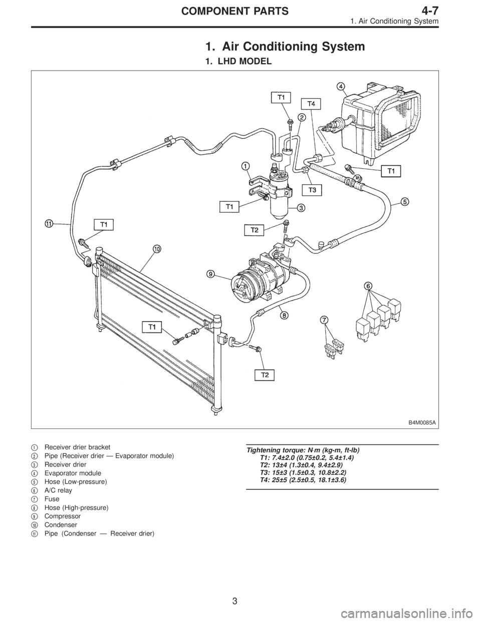
1. Air Conditioning System
1. LHD MODEL
B4M0085A
�1Receiver drier bracket
�
2Pipe (Receiver drier—Evaporator module)
�
3Receiver drier
�
4Evaporator module
�
5Hose (Low-pressure)
�
6A/C relay
�
7Fuse
�
8Hose (High-pressure)
�
9Compressor
�
10Condenser
�
11Pipe (Condenser—Receiver drier)
Tightening torque: N⋅m (kg-m, ft-lb)
T1: 7.4±2.0 (0.75±0.2, 5.4±1.4)
T2: 13±4 (1.3±0.4, 9.4±2.9)
T3: 15±3 (1.5±0.3, 10.8±2.2)
T4: 25±5 (2.5±0.5, 18.1±3.6)
3
4-7COMPONENT PARTS
1. Air Conditioning System
Page 864 of 2248
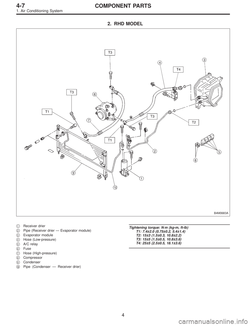
2. RHD MODEL
B4M0683A
�1Receiver drier
�
2Pipe (Receiver drier—Evaporator module)
�
3Evaporator module
�
4Hose (Low-pressure)
�
5A/C relay
�
6Fuse
�
7Hose (High-pressure)
�
8Compressor
�
9Condenser
�
10Pipe (Condenser—Receiver drier)
Tightening torque: N⋅m (kg-m, ft-lb)
T1: 7.4±2.0 (0.75±0.2, 5.4±1.4)
T2: 15±3 (1.5±0.3, 10.8±2.2)
T3: 15±5 (1.5±0.5, 10.8±3.6)
T4: 25±5 (2.5±0.5, 18.1±3.6)
4
4-7COMPONENT PARTS
1. Air Conditioning System
Page 869 of 2248

1. Safety Precautions
1. HFC-134a AIR CONDITIONING SYSTEM
Component parts of the cooling system, refrigerant, com-
pressor oil, and other parts are not the same for the HFC-
134a system and the older CFC-12 system. Do not inter-
change parts or liquid.
Vehicles with HFC-134a air conditioning systems, use only
HFC-134a parts that are indicated on a label attached to
the vehicle. Before performing any maintenance, verify the
type of air conditioning system installed in the vehicle.
B4M0686A
2. COMPRESSOR OIL
Do not use any compressor oil that is not specifically des-
ignated for the HFC-134a air conditioning system; only use
ZXL100PG. Also, do not use HFC-134a compressor oil in
the CFC-12 air conditioning system. If compression oils are
mixed, poor lubrication will result and the compressor itself
may be damaged.
Because HFC-134a compressor oil is very hygroscopic
(easily absorbs moisture), when parts of the air condition-
ing system are being removed, quickly install a blind plug
to prevent contact with the outside air. Also, always make
sure that the service container for compressor oil is tightly
closed except when in use. Store compressor oil in a tightly
closed steel container.
9
4-7SERVICE PROCEDURE
1. Safety Precautions