Page 178 of 2248
B2M0358
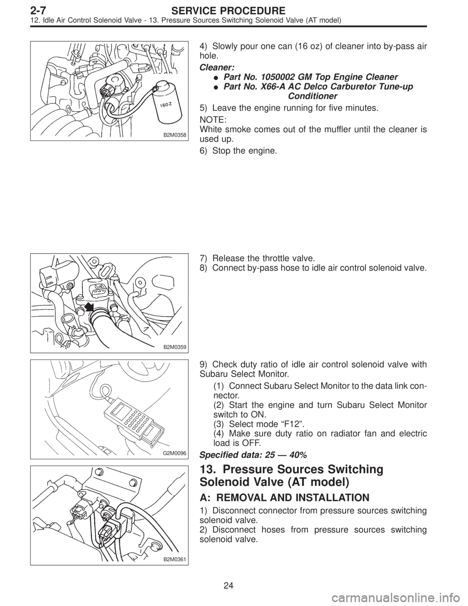
4) Slowly pour one can (16 oz) of cleaner into by-pass air
hole.
Cleaner:
�Part No. 1050002 GM Top Engine Cleaner
�Part No. X66-A AC Delco Carburetor Tune-up
Conditioner
5) Leave the engine running for five minutes.
NOTE:
White smoke comes out of the muffler until the cleaner is
used up.
6) Stop the engine.
B2M0359
7) Release the throttle valve.
8) Connect by-pass hose to idle air control solenoid valve.
G2M0096
9) Check duty ratio of idle air control solenoid valve with
Subaru Select Monitor.
(1) Connect Subaru Select Monitor to the data link con-
nector.
(2) Start the engine and turn Subaru Select Monitor
switch to ON.
(3) Select mode“F12”.
(4) Make sure duty ratio on radiator fan and electric
load is OFF.
Specified data: 25—40%
B2M0361
13. Pressure Sources Switching
Solenoid Valve (AT model)
A: REMOVAL AND INSTALLATION
1) Disconnect connector from pressure sources switching
solenoid valve.
2) Disconnect hoses from pressure sources switching
solenoid valve.
24
2-7SERVICE PROCEDURE
12. Idle Air Control Solenoid Valve - 13. Pressure Sources Switching Solenoid Valve (AT model)
Page 179 of 2248
B2M0358
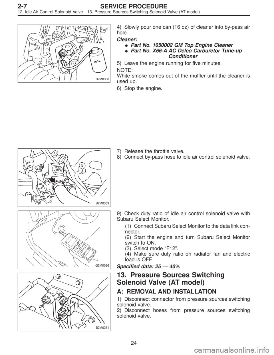
4) Slowly pour one can (16 oz) of cleaner into by-pass air
hole.
Cleaner:
�Part No. 1050002 GM Top Engine Cleaner
�Part No. X66-A AC Delco Carburetor Tune-up
Conditioner
5) Leave the engine running for five minutes.
NOTE:
White smoke comes out of the muffler until the cleaner is
used up.
6) Stop the engine.
B2M0359
7) Release the throttle valve.
8) Connect by-pass hose to idle air control solenoid valve.
G2M0096
9) Check duty ratio of idle air control solenoid valve with
Subaru Select Monitor.
(1) Connect Subaru Select Monitor to the data link con-
nector.
(2) Start the engine and turn Subaru Select Monitor
switch to ON.
(3) Select mode“F12”.
(4) Make sure duty ratio on radiator fan and electric
load is OFF.
Specified data: 25—40%
B2M0361
13. Pressure Sources Switching
Solenoid Valve (AT model)
A: REMOVAL AND INSTALLATION
1) Disconnect connector from pressure sources switching
solenoid valve.
2) Disconnect hoses from pressure sources switching
solenoid valve.
24
2-7SERVICE PROCEDURE
12. Idle Air Control Solenoid Valve - 13. Pressure Sources Switching Solenoid Valve (AT model)
Page 544 of 2248
G4M0520
6. Front Crossmember
A: REMOVAL
1) Disconnect ground cable from battery.
2) Loosen front wheel nuts.
3) Lift-up vehicle, and remove front tires and wheels.
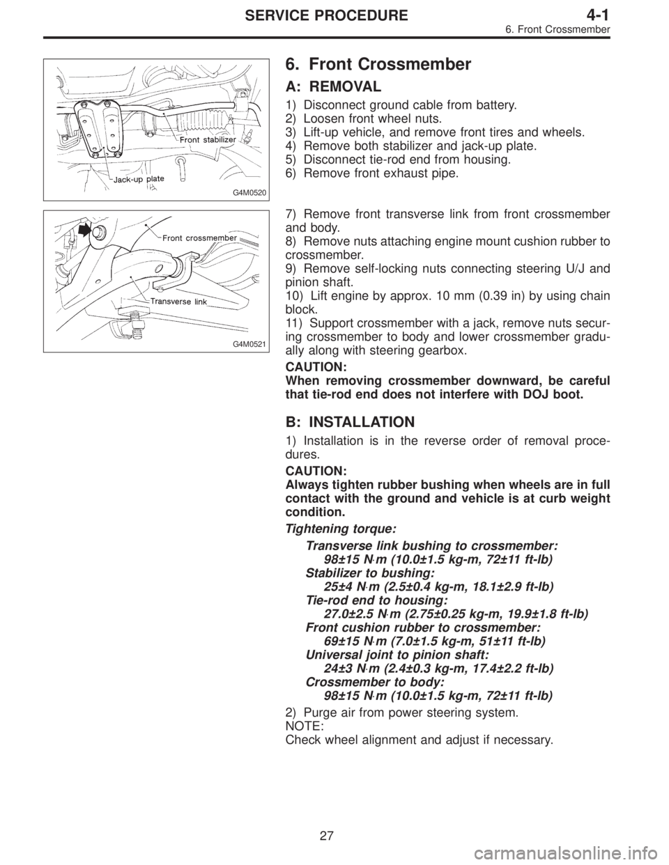
4) Remove both stabilizer and jack-up plate.
5) Disconnect tie-rod end from housing.
6) Remove front exhaust pipe.
G4M0521
7) Remove front transverse link from front crossmember
and body.
8) Remove nuts attaching engine mount cushion rubber to
crossmember.
9) Remove self-locking nuts connecting steering U/J and
pinion shaft.
10) Lift engine by approx. 10 mm (0.39 in) by using chain
block.
11) Support crossmember with a jack, remove nuts secur-
ing crossmember to body and lower crossmember gradu-
ally along with steering gearbox.
CAUTION:
When removing crossmember downward, be careful
that tie-rod end does not interfere with DOJ boot.
B: INSTALLATION
1) Installation is in the reverse order of removal proce-
dures.
CAUTION:
Always tighten rubber bushing when wheels are in full
contact with the ground and vehicle is at curb weight
condition.
Tightening torque:
Transverse link bushing to crossmember:
98±15 N⋅m (10.0±1.5 kg-m, 72±11 ft-lb)
Stabilizer to bushing:
25±4 N⋅m (2.5±0.4 kg-m, 18.1±2.9 ft-lb)
Tie-rod end to housing:
27.0±2.5 N⋅m (2.75±0.25 kg-m, 19.9±1.8 ft-lb)
Front cushion rubber to crossmember:
69±15 N⋅m (7.0±1.5 kg-m, 51±11 ft-lb)
Universal joint to pinion shaft:
24±3 N⋅m (2.4±0.3 kg-m, 17.4±2.2 ft-lb)
Crossmember to body:
98±15 N⋅m (10.0±1.5 kg-m, 72±11 ft-lb)
2) Purge air from power steering system.
NOTE:
Check wheel alignment and adjust if necessary.
27
4-1SERVICE PROCEDURE
6. Front Crossmember
Page 637 of 2248
G4M0114
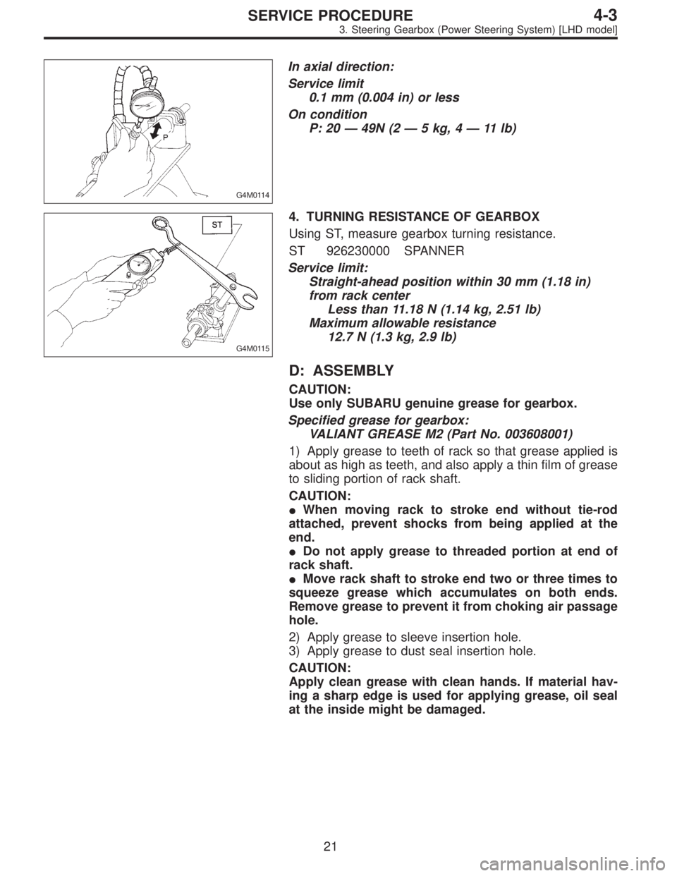
In axial direction:
Service limit
0.1 mm (0.004 in) or less
On condition
P: 20—49N (2—5 kg, 4—11 lb)
G4M0115
4. TURNING RESISTANCE OF GEARBOX
Using ST, measure gearbox turning resistance.
ST 926230000 SPANNER
Service limit:
Straight-ahead position within 30 mm (1.18 in)
from rack center
Less than 11.18 N (1.14 kg, 2.51 lb)
Maximum allowable resistance
12.7 N (1.3 kg, 2.9 lb)
D: ASSEMBLY
CAUTION:
Use only SUBARU genuine grease for gearbox.
Specified grease for gearbox:
VALIANT GREASE M2 (Part No. 003608001)
1) Apply grease to teeth of rack so that grease applied is
about as high as teeth, and also apply a thin film of grease
to sliding portion of rack shaft.
CAUTION:
�When moving rack to stroke end without tie-rod
attached, prevent shocks from being applied at the
end.
�Do not apply grease to threaded portion at end of
rack shaft.
�Move rack shaft to stroke end two or three times to
squeeze grease which accumulates on both ends.
Remove grease to prevent it from choking air passage
hole.
2) Apply grease to sleeve insertion hole.
3) Apply grease to dust seal insertion hole.
CAUTION:
Apply clean grease with clean hands. If material hav-
ing a sharp edge is used for applying grease, oil seal
at the inside might be damaged.
21
4-3SERVICE PROCEDURE
3. Steering Gearbox (Power Steering System) [LHD model]
Page 651 of 2248
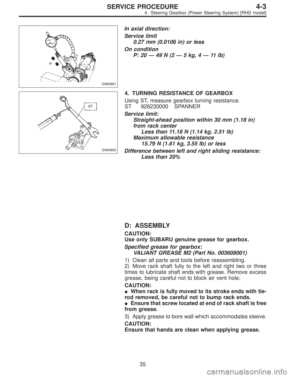
G4M0801
In axial direction:
Service limit
0.27 mm (0.0106 in) or less
On condition
P: 20—49N(2—5 kg, 4—11 lb)
G4M0802
4. TURNING RESISTANCE OF GEARBOX
Using ST, measure gearbox turning resistance.
ST 926230000 SPANNER
Service limit:
Straight-ahead position within 30 mm (1.18 in)
from rack center
Less than 11.18 N (1.14 kg, 2.51 lb)
Maximum allowable resistance
15.79 N (1.61 kg, 3.55 lb) or less
Difference between left and right sliding resistance:
Less than 20%
D: ASSEMBLY
CAUTION:
Use only SUBARU genuine grease for gearbox.
Specified grease for gearbox:
VALIANT GREASE M2 (Part No. 003608001)
1) Clean all parts and tools before reassembling.
2) Move rack shaft fully to the left and right two or three
times to lubricate shaft ends with grease. Remove excess
grease, being careful not to block air vent hole.
CAUTION:
�When rack is fully moved to its stroke ends with tie-
rod removed, be careful not to bump rack ends.
�Ensure that screw located at end of rack shaft is free
from grease.
3) Apply grease to bore wall which accommodates sleeve.
CAUTION:
Ensure that hands are clean when applying grease.
35
4-3SERVICE PROCEDURE
4. Steering Gearbox (Power Steering System) [RHD model]
Page 652 of 2248
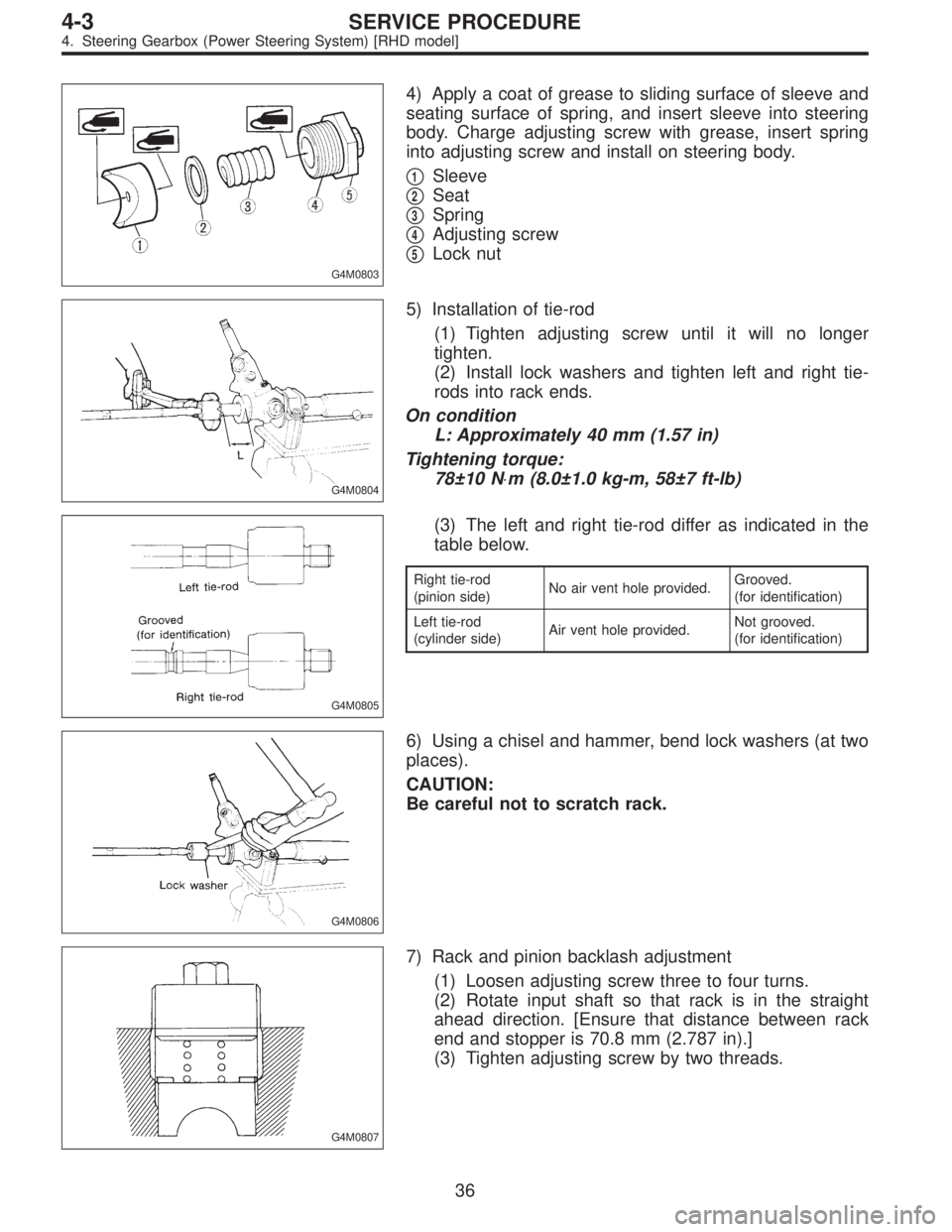
G4M0803
4) Apply a coat of grease to sliding surface of sleeve and
seating surface of spring, and insert sleeve into steering
body. Charge adjusting screw with grease, insert spring
into adjusting screw and install on steering body.
�
1Sleeve
�
2Seat
�
3Spring
�
4Adjusting screw
�
5Lock nut
G4M0804
5) Installation of tie-rod
(1) Tighten adjusting screw until it will no longer
tighten.
(2) Install lock washers and tighten left and right tie-
rods into rack ends.
On condition
L: Approximately 40 mm (1.57 in)
Tightening torque:
78±10 N⋅m (8.0±1.0 kg-m, 58±7 ft-lb)
G4M0805
(3) The left and right tie-rod differ as indicated in the
table below.
Right tie-rod
(pinion side)No air vent hole provided.Grooved.
(for identification)
Left tie-rod
(cylinder side)Air vent hole provided.Not grooved.
(for identification)
G4M0806
6) Using a chisel and hammer, bend lock washers (at two
places).
CAUTION:
Be careful not to scratch rack.
G4M0807
7) Rack and pinion backlash adjustment
(1) Loosen adjusting screw three to four turns.
(2) Rotate input shaft so that rack is in the straight
ahead direction. [Ensure that distance between rack
end and stopper is 70.8 mm (2.787 in).]
(3) Tighten adjusting screw by two threads.
36
4-3SERVICE PROCEDURE
4. Steering Gearbox (Power Steering System) [RHD model]
Page 656 of 2248
![SUBARU LEGACY 1995 Service Repair Manual 5. Control Valve (Power Steering
Gearbox) [LHD model]
NOTE:
This section focuses on the disassembly and reassembly
of control valve. For the inspection and adjustment and the
service procedures for as SUBARU LEGACY 1995 Service Repair Manual 5. Control Valve (Power Steering
Gearbox) [LHD model]
NOTE:
This section focuses on the disassembly and reassembly
of control valve. For the inspection and adjustment and the
service procedures for as](/manual-img/17/57432/w960_57432-655.png)
5. Control Valve (Power Steering
Gearbox) [LHD model]
NOTE:
This section focuses on the disassembly and reassembly
of control valve. For the inspection and adjustment and the
service procedures for associated parts, refer to“Steering
Gearbox”.
G4M0136
�1Power cylinder
�
2Cylinder
�
3Rack piston
�
4Rack axle
�
5Input shaft�
6Torsion bar
�
7Valve housing
�
8Valve body
�
9Control valve�
10Pipe B
�
11Pipe A
�
12Pinion
�
13Pinion axle
A: CHECKING OIL LEAKING POINTS
1. OIL LEAKING POINTS
1) If leak point is other than a, b, c, or d, perform check
step 5) in [W5A2] before dismounting gearbox from
vehicle. If gearbox is dismounted without confirming where
the leak is, it must be mounted again to locate the leak
point.
2) Even if the location of the leak can be easily found by
observing the leaking condition, it is necessary to thor-
oughly remove the oil from the suspected portion and turn
the steering wheel from lock to lock about 30 to 40 times
with engine running, then make comparison of the sus-
pected portion between immediately after and several
hours after this operation.
3) Before starting oil leak repair work, be sure to clean the
gearbox, hoses, pipes, and surrounding parts. After com-
pleting repair work, clean these areas again.
40
4-3SERVICE PROCEDURE
5. Control Valve (Power Steering Gearbox) [LHD model]
Page 665 of 2248
![SUBARU LEGACY 1995 Service Repair Manual 6. Control Valve (Power Steering
Gearbox) [RHD model]
NOTE:
This section focuses on the disassembly and reassembly
of control valve. For the inspection and adjustment and the
service procedures for as SUBARU LEGACY 1995 Service Repair Manual 6. Control Valve (Power Steering
Gearbox) [RHD model]
NOTE:
This section focuses on the disassembly and reassembly
of control valve. For the inspection and adjustment and the
service procedures for as](/manual-img/17/57432/w960_57432-664.png)
6. Control Valve (Power Steering
Gearbox) [RHD model]
NOTE:
This section focuses on the disassembly and reassembly
of control valve. For the inspection and adjustment and the
service procedures for associated parts, refer to“Steering
Gearbox”.
B4M0668A
A: CHECKING OIL LEAKING POINTS
1. OIL LEAKING POINTS
1) If leak point is other than a, b, c, or d, perform check
step 5) in [W6A2] before dismounting gearbox from
vehicle. If gearbox is dismounted without confirming where
the leak is, it must be mounted again to locate the leak
point.
2) Even if the location of the leak can be easily found by
observing the leaking condition, it is necessary to thor-
oughly remove the oil from the suspected portion and turn
the steering wheel from lock to lock about 30 to 40 times
with engine running, then make comparison of the sus-
pected portion between immediately after and several
hours after this operation.
3) Before starting oil leak repair work, be sure to clean the
gearbox, hoses, pipes, and surrounding parts. After com-
pleting repair work, clean these areas again.
49
4-3SERVICE PROCEDURE
6. Control Valve (Power Steering Gearbox) [RHD model]