1995 NISSAN ALMERA N15 check oil
[x] Cancel search: check oilPage 687 of 1701
SMA525AON-VEHICLE
SERVICE
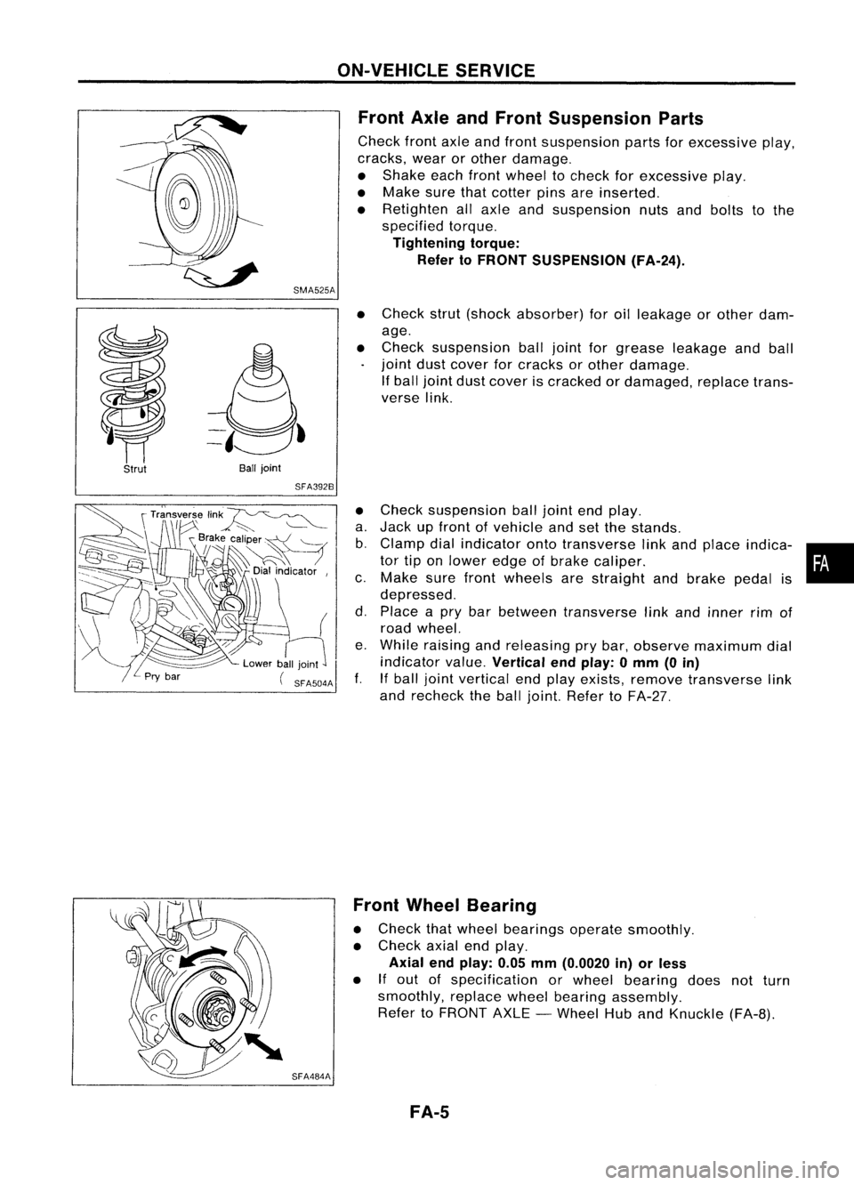
Front AxleandFront Suspension Parts
Check frontaxleandfront suspension partsforexcessive play,
cracks, wearorother damage.
• Shake eachfrontwheel tocheck forexcessive play.
• Make surethatcotter pinsareinserted.
• Retighten allaxle andsuspension nutsandbolts tothe
specified torque.
Tightening torque:
Refer toFRONT SUSPENSION (FA-24).
Strut
Ball
joint
SFA392B
•
Check strut(shock absorber) foroilleakage orother dam-
age.
• Check suspension balljoint forgrease leakage andball
joint dustcover forcracks orother damage.
If ball joint dustcover iscracked ordamaged, replacetrans-
verse link.
• Check suspension balljoint endplay.
a. Jack upfront ofvehicle andsetthe stands.
b. Clamp dialindicator ontotransverse linkand place indica- •
tor tiponlower edgeofbrake caliper. •
c. Make surefront wheels arestraight andbrake pedalis
depressed.
d. Place apry bar between transverse linkand inner rimof
road wheel.
e. While raising andreleasing prybar, observe maximum dial
indicator value.
Vertical endplay: 0mm (0in)
f. Ifball joint vertical endplay exists, remove transverse link
and recheck theball joint. Refer toFA-27.
SFA484A Front
Wheel Bearing
• Check thatwheel bearings operatesmoothly.
• Check axialendplay.
Axial endplay: 0.05mm(0.0020 in)orless
• If
out ofspecification orwheel bearing doesnotturn
smoothly, replacewheelbearing assembly.
Refer toFRONT AXLE-Wheel HubandKnuckle (FA-B).
FA-5
Page 688 of 1701
ON-VEHICLESERVICE
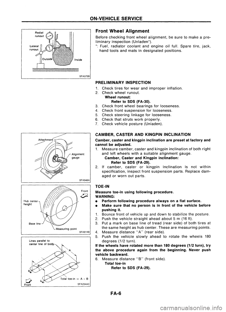
Front Wheel Alignment
Before checking frontwheel alignment, besure tomake apre-
liminary inspection (Unladen*).
*: Fuel, radiator coolantandengine oilfull. Spare tire,jack,
hand tools andmats indesignated positions.
SFA575B PRELIMINARY INSPECTION
1. Check tiresforwear andimproper inflation.
2. Check wheelrunout.
Wheel runout:
Refer toSOS (FA-30).
3. Check frontwheel bearings forlooseness.
4. Check frontsuspension forlooseness.
5. Check steering linkageforlooseness.
6. Check thatstruts workproperly.
7. Check vehicle posture (Unladen).
TOE-IN Measure toe-inusingfollowing procedure.
WARNING:
• Perform following procedure alwaysonaflat surface.
• Make surethatnoperson isin front ofthe vehicle before
pushing it.
1. Bounce frontofvehicle upand down tostabilize theposture.
2. Push thevehicle straight aheadabout5m (16 ft).
3. Put amark onbase lineoftread (rearside) ofboth tires at
the same height ashub center. Thesearemeasuring points.
4. Measure distance"A"(rear side).
5. Push thevehicle slowlyaheadtorotate thewheels 180
degrees (1/2turn).
If the wheels haverotated morethan180degrees
(112
turn), try
the above procedure againfromthebeginning. Neverpush
vehicle backward.
6. Measure distance"B"(front side).
Total toe-in
Refer toSOS (FA-29).
CAMBER,
CASTERANDKINGPIN INCLINATION
Camber, casterandkingpin inclination arepreset atfactory and
cannot beadjusted.
1. Measure camber,casterandkingpin inclination ofboth right
and leftwheels withasuitable alignment gauge.
Camber, CasterandKingpin inclination:
Refer toSOS (FA-29).
2. Ifcamber, casterorkingpin inclination isnot within
specification, inspectfrontsuspension parts.Replace dam-
aged orworn outparts.
Front
SFA948A
SFA614B
SFA234AC
Lines
parallel to
center lineofbody
Q
Front
Hub
center
height
FA-6
Page 693 of 1701
SFA496AFRONT
AXLE
Wheel HubandKnuckle (Cont'd)
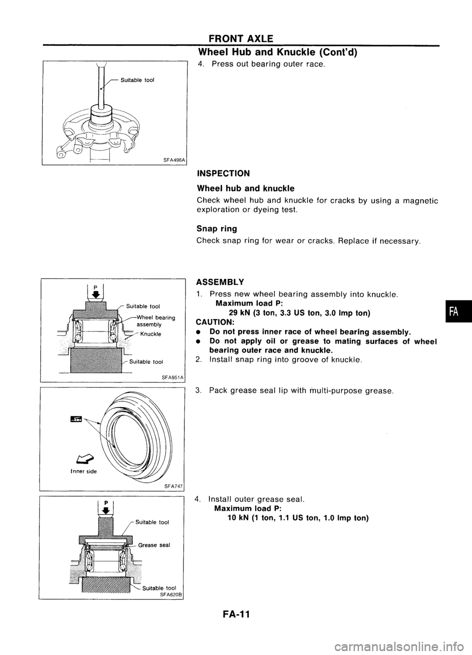
4. Press outbearing outerrace.
INSPECTION
Wheel hubandknuckle
Check wheel huband knuckle forcracks byusing amagnetic
exploration ordyeing test.
Snap ring
Check snapringforwear orcracks. Replace ifnecessary.
Wheel bearing
assembly
~ Knuckle
SFA951A
SFA747
Suitable tool
SFA620B ASSEMBLY
1. Press newwheel bearing assembly intoknuckle.
Maximum loadP: •
29 kN (3ton, 3.3USton, 3.0Imp ton)
i
CAUTION:
• Donot press innerraceofwheel bearing assembly.
• Do not apply oilorgrease tomating surfaces ofwheel
bearing outerraceandknuckle.
2. Install snapringintogroove ofknuckle.
3. Pack grease seallipwith multi-purpose grease.
4. Install outergrease seal.
Maximum loadP:
10 kN (1ton, 1.1USton, 1.0Imp ton)
FA-11
Page 707 of 1701
Suitable
bar
SFA610BFRONT
SUSPENSION
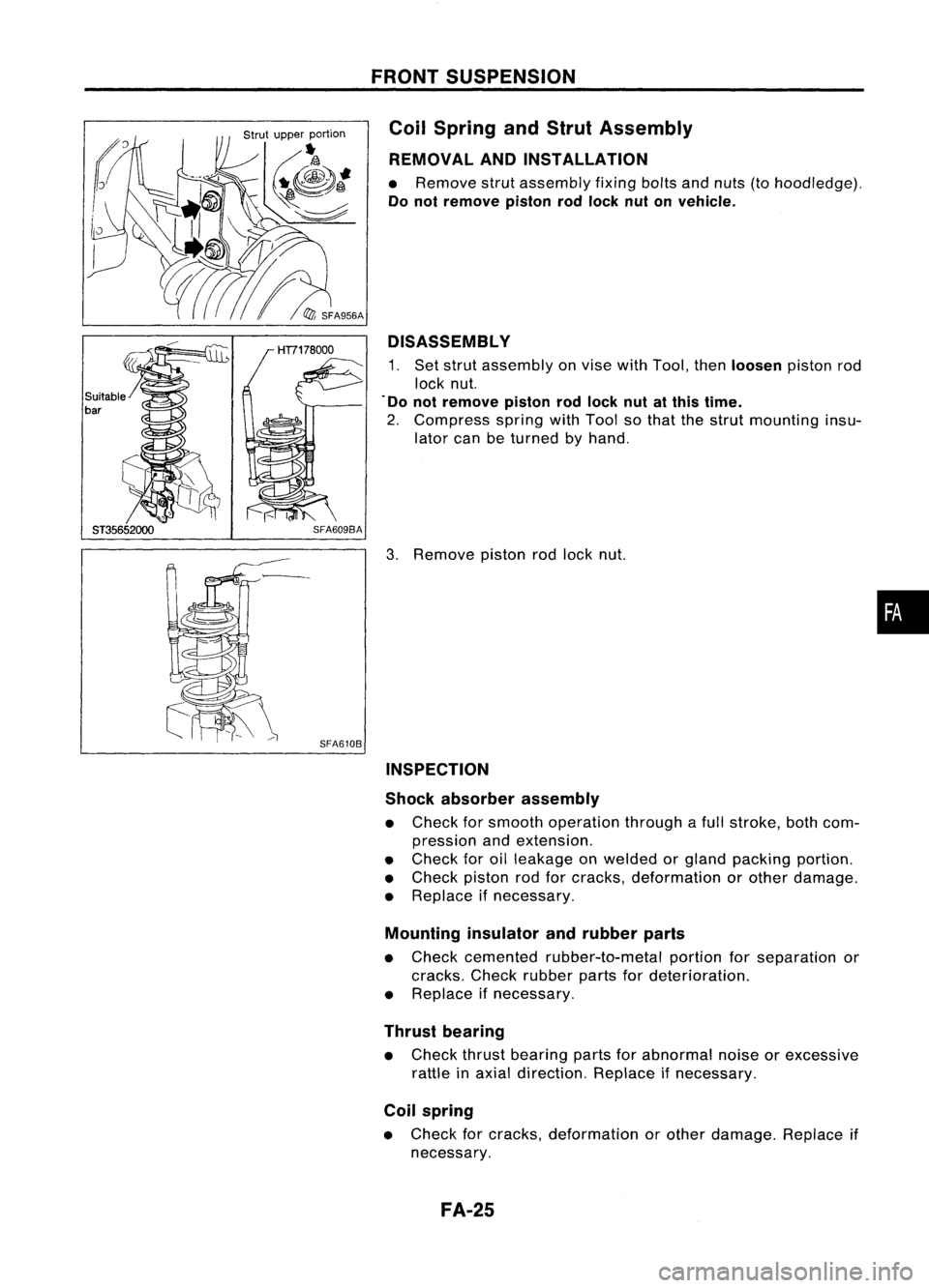
Coil Spring andStrut Assembly
REMOVAL ANDINSTALLATION
• Remove strutassembly fixingboltsandnuts (tohoodledge).
Do not remove pistonrodlock nutonvehicle.
DISASSEMBL Y
1. Set strut assembly onvise withTool, then
loosen
pistonrod
lock nut.
. Do not remove pistonrodlock nutatthis time.
2. Compress springwithTool sothat thestrut mounting insu-
lator canbeturned byhand.
3. Remove pistonrodlock nut.
INSPECTION
Shock absorber assembly
• Check forsmooth operation throughafull stroke, bothcom-
pression andextension.
• Check foroilleakage onwelded orgland packing portion.
• Check pistonrodforcracks, deformation orother damage.
• Replace ifnecessary.
Mounting insulatorandrubber parts
• Check cemented rubber-to-metal portionforseparation or
cracks. Checkrubber partsfordeterioration.
• Replace ifnecessary.
Thrust bearing
• Check thrustbearing partsforabnormal noiseorexcessive
rattle inaxial direction. Replaceifnecessary.
Coil spring
• Check forcracks, deformation orother damage. Replaceif
necessary.
FA-25
•
Page 721 of 1701
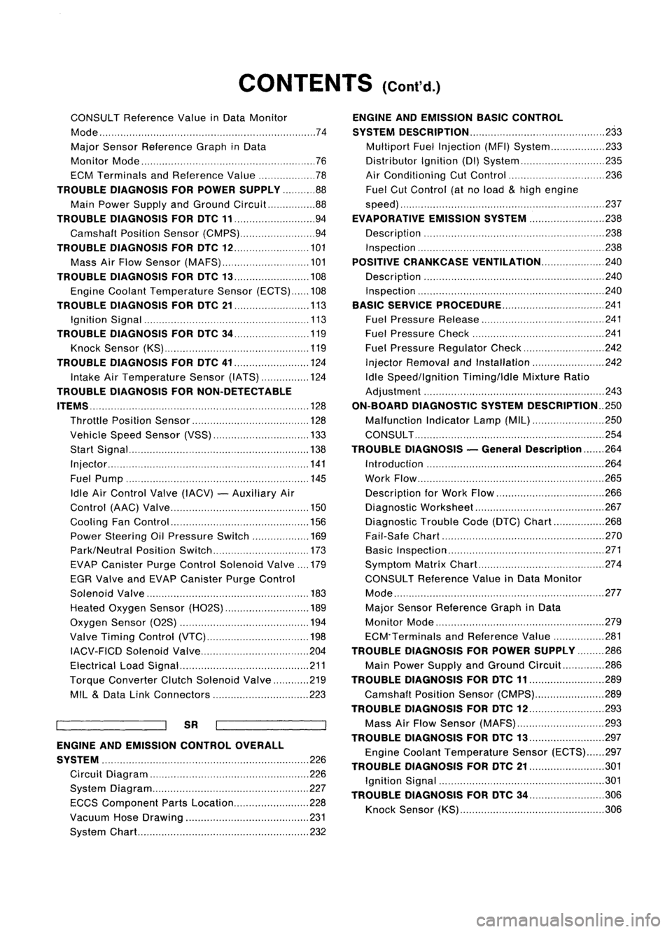
CONTENTS(Cont'd.)
CONSULT Reference ValueinData Monitor
Mode 74
Major Sensor Reference GraphinData
Monitor Mode 76
ECM Terminals andReference Value 78
TROUBLE DIAGNOSIS FORPOWER SUPPLY 88
Main Power Supply andGround Circuit.. 88
TROUBLE DIAGNOSIS FORDTC11 94
Camshaft PositionSensor(CMPS) 94
TROUBLE DIAGNOSIS FORDTC
12 101
Mass AirFlow Sensor (MAFS) 101
TROUBLE DIAGNOSIS FORDTC
13 108
Engine Coolant Temperature Sensor(ECTS) 108
TROUBLE DIAGNOSIS FORDTC
21 113
Ignition Signal 113
TROUBLE DIAGNOSIS FORDTC
34 119
Knock Sensor (KS) 119
TROUBLE DIAGNOSIS FORDTC
41 124
Intake AirTemperature Sensor(IATS) 124
TROUBLE DIAGNOSIS FORNON-DETECTABLE
ITEMS , '"
.128
Throttle Position Sensor 128
Vehicle SpeedSensor (VSS) 133
Start Signal 138
Injector 141
Fuel Pump 145
Idle AirControl Valve(IACV) -Auxiliary Air
Control (AAC)Valve 150
Cooling FanControl 156
Power Steering OilPressure Switch 169
Park/Neutral PositionSwitch 173
EVAP Canister PurgeControl Solenoid Valve179
EGR Valve andEVAP Canister PurgeControl
Solenoid Valve 183
Heated Oxygen Sensor(H02S) 189
Oxygen Sensor(02S) 194
Valve Timing Control (VTC) 198
IACV-FICD SolenoidValve 204
Electrical LoadSignal 211
Torque Converter ClutchSolenoid Valve 219
MIL
&
Data LinkConnectors 223
SR
ENGINE ANDEMISSION CONTROL OVERALL
SYSTE M
226
Circuit Diagram 226
System Diagram 227
ECCS Component PartsLocation 228
Vacuum HoseDrawing 231
System Chart... 232
ENGINE
ANDEMISSION BASICCONTROL
SYSTEM DESCRiPTION
233
Multipart FuelInjection (MFI)System 233
Distributor Ignition
(01)
System 235
Air Conditioning CutControl 236
Fuel CutControl (atnoload
&
high engine
speed) 237
EVAPORATIVE EMISSIONSYSTEM
238
Description 238
Inspection 238
POSITIVE CRANKCASE VENTILATION
240
Description 240
Inspection 240
BASIC SERVICE
PROCEDURE 241
Fuel Pressure Release 241
Fuel Pressure Check 241
Fuel Pressure Regulator Check 242
Injector Removal andInstallation 242
Idle Speed/Ignition Timing/IdleMixtureRatio
Adjustment 243
ON-BOARD DIAGNOSTIC SYSTEMDESCRIPTION ..250
Malfunction IndicatorLamp(MIL) 250
CONSULT 254
TROUBLE DIAGNOSIS -General Description
264
Introduction 264
Work Flow 265
Description forWork Flow 266
Diagnostic Worksheet 267
Diagnostic TroubleCode(DTC) Chart 268
Fail-Safe Chart 270
Basic Inspection 271
Symptom MatrixChart. 274
CONSULT Reference ValueinData Monitor
Mode 277
Major Sensor Reference GraphinData
Monitor Mode 279
ECM"Terminals andReference Value 281
TROUBLE DIAGNOSIS FORPOWER SUPPLY
286
Main Power Supply andGround Circuit.. 286
TROUBLE DIAGNOSIS FORDTC
11 289
Camshaft PositionSensor(CMPS) 289
TROUBLE DIAGNOSIS FORDTC
12 293
Mass AirFlow Sensor (MAFS) 293
TROUBLE DIAGNOSIS FORDTC
13 297
Engine Coolant Temperature Sensor(ECTS) 297
TROUBLE DIAGNOSIS FORDTC
21 301
Ignition Signal 301
TROUBLE DIAGNOSIS FORDTC
34 306
Knock Sensor (KS) 306
Page 722 of 1701
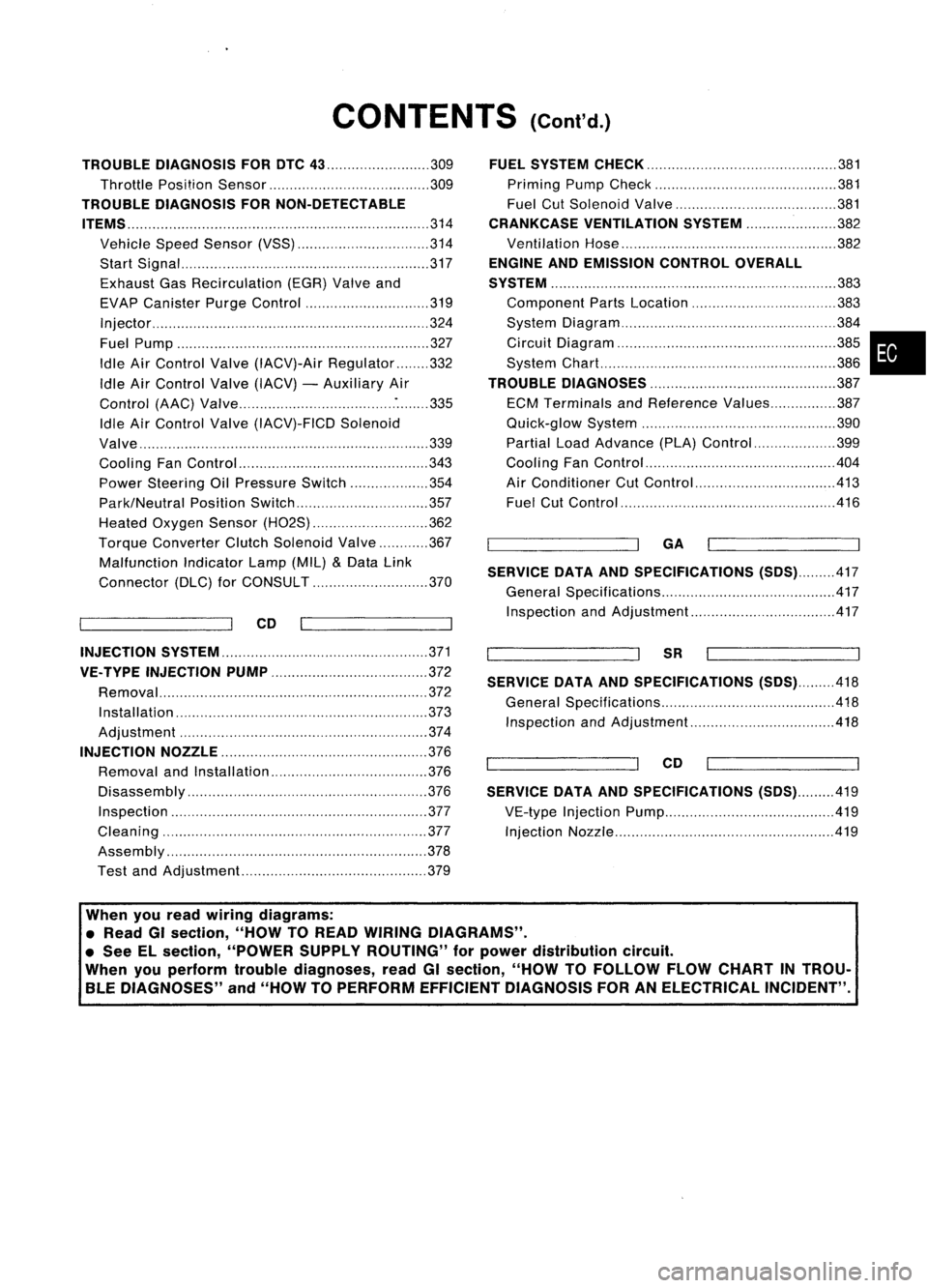
CONTENTS(Cont'd.)
TROUBLE DIAGNOSIS FORDTC
43 309
Throttle Position Sensor 309
TROUBLE DIAGNOSIS FORNON-DETECTABLE
ITEMS
314
Vehicle SpeedSensor (VSS) 314
Start Signal 317
Exhaust GasRecirculation (EGR)Valveand
EVAP Canister PurgeControl 319
Injector 324
Fuel Pump 327
Idle AirControl Valve(IACV)-Air Regulator 332
Idle AirControl Valve(IACV) -Auxiliary Air
Control (AAC)Valve :335
Idle AirControl Valve(IACV)-FICD Solenoid
Valve '"339
Cooling FanControl 343
Power Steering OilPressure Switch 354
Park/Neutral PositionSwitch 357
Heated Oxygen Sensor(H02S) 362
Torque
Converter
ClutchSolenoid Valve 367
Malfunction IndicatorLamp(MIL)
&
Data Link
Connector (DLC)forCONSULT 370
CD
INJECTION SYSTEM
371
VE.TYPE INJECTION PUMP
372
Removal 372
Installation 373
Adjustment 374
INJECTION NOZZLE
376
Removal andInstallation 376
Disassembly 376
Inspection 377
Cleaning 377
Assembly 378
Test andAdjustment 379
FUEL
SYSTEM CHECK
381
Priming PumpCheck 381
Fuel CutSolenoid Valve 381
CRANKCASE VENTILATION SYSTEM
382
Ventilation Hose 382
ENGINE ANDEMISSION CONTROLOVERALL
SYSTEM
383
Component PartsLocation 383
System Diagram 384
Circuit Diagram ,385
System Chart. 386
TROUBLE DIAGNOSES
387
ECM Terminals andReference Values 387
Quick-glow System 390
Partial LoadAdvance (PLA)Control 399
Cooling FanControl 404
Air Conditioner CutControl 413
Fuel CutControl 416
GA
SERVICE DATAANDSPECIFICATIONS
(505).417
General Specifications 417
Inspection andAdjustment.. 417
SR
SERVICE DATAANDSPECIFICATIONS
(505).418
General Specifications 418
Inspection andAdjustment.. .418
CD
SERVICE DATAANDSPECIFICATIONS
(505).419
VE-type Injection Pump 419
Injection Nozzle 419
•
When youread wiring diagrams:
• Read GIsection, "HOWTOREAD WIRING DIAGRAMS" .
• See Elsection, "POWER SUPPLYROUTING" forpower distribution circuit.
When youperform troublediagnoses, readGIsection, "HOWTOFOllOW FLOWCHART INTROU-
BLE DIAGNOSES" and"HOW TOPERFORM EFFICIENT DIAGNOSIS FORANELECTRICAL INCIDENT".
Page 754 of 1701

BASICSERVICE PROCEDURE
Idle Speedllgnition TiminglldleMixtureRatio
Adjustment
PREPARATION
• Make surethatthefollowing partsarein
good order.
(1) Battery
(2) Ignition system
(3) Engine oiland coolant levels
(4) Fuses
(5) ECM harness connector
(6) Vacuum hoses
(7) Airintake system
(Oil filler cap,oillevel gauge, etc.)
(8) Fuel pressure
(9)' Engine compression
(10) Throttle valve
(11) EGR valve operation -For Europe and
Israel andAustralia, andGA15DE M/Tmod-
els
Overall inspection sequence
INSPECTION
(12)
Evaporative emissionsystem
• On models equipped withairconditioner,
checks shouldbecarried outwhile theair
conditioner is"OFF".
• On models equipped withautomatic
transaxle, whenchecking idlespeed, ignition
timing andmixture ratio,checks shouldbe
carried outwhile shiftlever isin
"N"
position.
• When measuring
"CO"
percentage, insert
probe morethan40cm (15.7 in)into tailpipe .•
• Turn offheadlamps, heaterblower, rear
defogger.
• Keep frontwheels pointed straight ahead.
• Make thecheck afterthecooling fanhas
stopped.
Perform diagnostic testmode
1/
(Self-diagnostic results).
Check
&
adjust ignition timing.
Check
&
adjust idlespeed. NG
Repair orreplace.
Check oxygen sensor*1 function.
OK
Check
oxygen sensor*1 har-
ness.
Check CO%.
NG
NG
Repair orreplace harness.
OK Replace oxygensensor*1.
INSPECTION END Check
emission controlparts NGCheck oxygen sensor*1 function. OK
and repair orreplace ifneces-
sary.
*1: Heated oxygen sensor(ForEurope andIsrael, andAustralia AfTmodels)
Oxygen sensor(Except forEurope andIsrael, andAustralia AfTmodels)
EC-35
Page 772 of 1701

ON-BOARDDIAGNOSTIC SYSTEMDESCRIPTION
CONSULT (Cont'd)
ACTIVE TESTMODE
TEST ITEM CONDITION JUDGEMENT
CHECKITEM(REMEDY)
• Engine: Returntothe original
•Harness andconnector
FUEL INJECTION trouble
condition If
trouble symptom disappears,
•Fuel injectors
• Change theamount offuel see
CHECK ITEM.
injection usingCONSULT . •
Oxygen sensor*1
• Engine: Afterwarming up,idle
IACV-AACIV the
engine.
Enginespeedchanges according •Harness andconnector
OPENING •
Change theIACV-AAC valve
tothe opening percent. •
IACV-AAC valve
opening percentusingCON-
SULT.
• Engine: Returntothe original
•Harness andconnector
ENG COOLANT trouble
condition
Iftrouble symptom disappears, •
Engine coolant temperature
TEMP •
Change theengine coolant
.
see CHECK ITEM. sensor
temperature indicationusing
•Fuel injectors
CONSULT.
• Engine: Returntothe original
trouble condition
Iftrouble symptom disappears,
IGNITION TIMING•
Timing light:Set •
Adjust initialignition timing
• Retard theignition timingusingsee
CHECK ITEM.
CONSULT .
• Engine: Afterwarming up,idle •
Harness andconnector
the engine. •
Compression
POWER •
A/C switch "OFF"
Enginerunsrough ordies . •
Injectors
BALANCE •
Shift lever "N" •
Power transistor
• Cut offeach injector signalone •
Spark plugs
at atime using CONSULT. •
Ignition coils
• Ignition switch:ON
COOLING FAN*3•
Turn thecooling fan"ON" and
Cooling fanmoves andstops. •
Harness andconnector
"OFF", or"LOW" and"HI" •
Cooling fanmotor
and "OFF" usingCONSULT .
• Ignition switch:ON(Engine
FUEL PUMP stopped)
Fuelpump relaymakes theoper- •Harness andconnector
• Turn thefuel pump relay"ON"
RELAY and"OFF" usingCONSULT ating
sound. •
Fuel pump relay
and listen tooperating sound.
EGRC SOLENOID
VALVE (EVAP canister
•Ignition switch:ON
purge control
•Turn solenoid valve"ON" and Solenoid
valvemakes anoperat- •
Harness andconnector
solenoid valveor
EGR valve
&
"OFF"
withtheCONSULT andingsound. •
Solenoid valve
EVAP canister listen
tooperating sound.
purge control
solenoid valve)
•Ignition switch:ON
VALVE TIMING •
Turn solenoid valve"ON" and Solenoid
valvemakes anoperat- •
Harness andconnector
SOL*2 "OFF"
usingCONSULT anding
sound. •
Solenoid valve
listen tooperating sound.
SELF-LEARNING •
Inthis test, thecoefficient ofself-learning controlmixture ratioreturns tothe original coefficient by
CONT touching
"CLEAR" onthe screen.
*1: Heated oxygen sensor(ForEurope andIsrael, andAustralia A/Tmodels)
Oxygen sensor(Except forEurope andIsrael, andAustralia A/Tmodels)
*2: GA16DE except forEurope andIsrael
*3: GA16DE engine A/Tmodels forEurope without heavydutykithave a2- step control [ON/OFF] system."LOW"and"HI"
are shown onCONSULT screentorepresent "ON"condition.
EC-53
•