Page 292 of 1701

AD22VF SBR776B
SBR772 FRONT
DISCBRAKE
Removal
WARNING:
Clean brakepadswithavacuum dustcollector tominimize the
hazard ofairborne asbestos orother materials.
CAUTION:
Suspend caliperassembly withwire soasnot tostretch brake
hose.
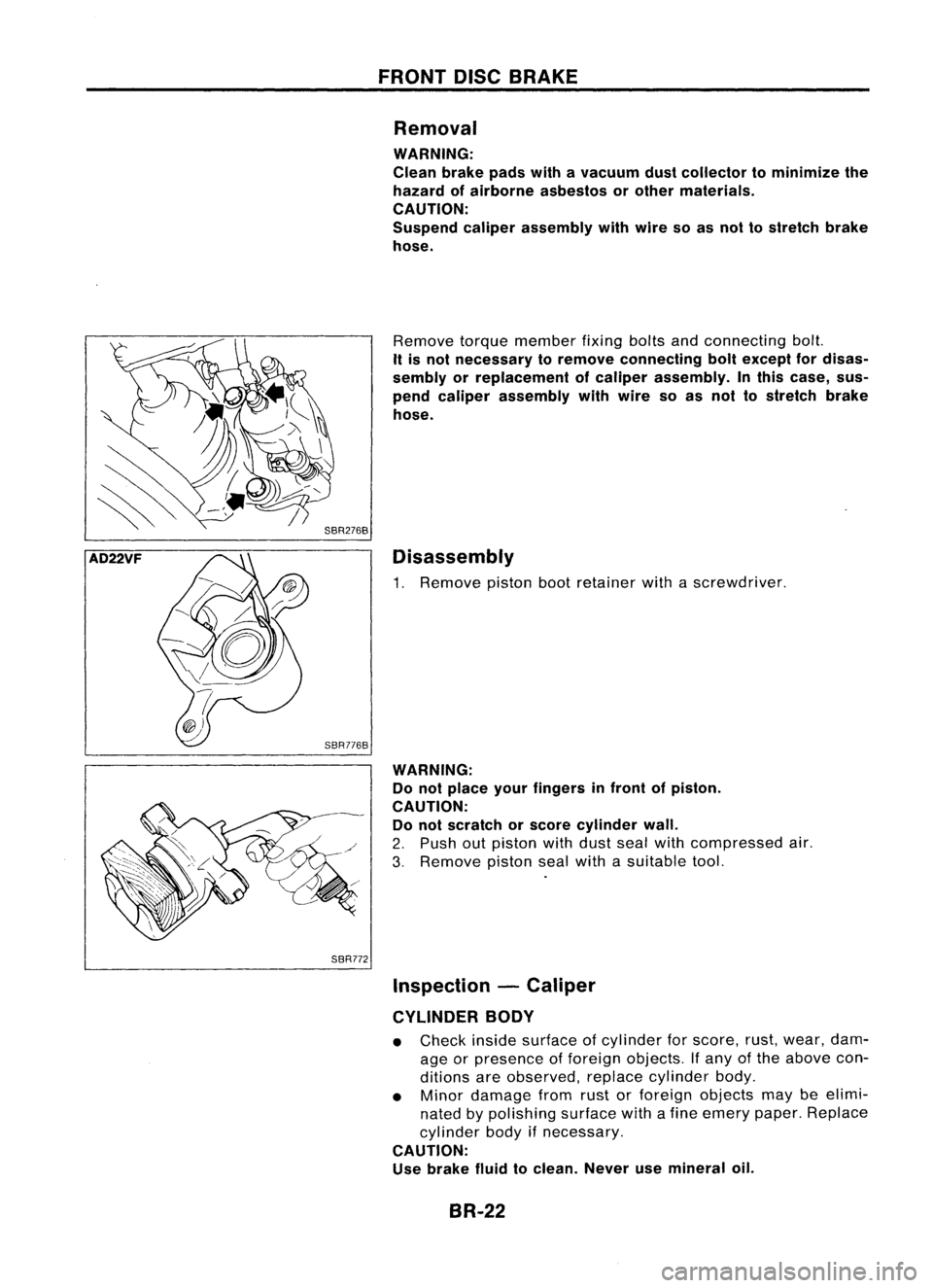
Remove torquemember fixingboltsandconnecting bolt.
It is not necessary toremove connecting boltexcept fordisas-
sembly orreplacement ofcaliper assembly. Inthis case, sus-
pend caliper assembly withwire soas not tostretch brake
hose.
Disassembly
1. Remove pistonbootretainer withascrewdriver.
WARNING: Do not place yourfingers infront ofpiston.
CAUTION: Do not scratch orscore cylinder wall.
2. Push outpiston withdust sealwithcompressed air.
3. Remove pistonsealwith asuitable tool.
Inspection -Caliper
CYLINDER BODY
• Check insidesurface ofcylinder forscore, rust,wear, dam-
age orpresence offoreign objects. Ifany ofthe above con-
ditions areobserved, replacecylinder body.
• Minor damage fromrustorforeign objects maybeelimi-
nated bypolishing surfacewithafine emery paper.Replace
cylinder bodyifnecessary.
CAUTION: Use brake fluidtoclean. Neverusemineral oil.
BR-22
Page 302 of 1701

l
--,II
~//
SBR656
SBR026D REAR
DISCBRAKE
Disassembly (Cont'd)
c. Remove pistonseal.
Be careful nottodamage cylinderbody.
4. Remove returnspring, toggleleverandcable guide.
Inspection -Caliper
CAUTION: Use brake fluidtoclean cylinder. Neverusemineral
oil.
CYLINDER BODY
• Check insidesurface ofcylinder forscore, rust,wear, dam-
age orpresence offoreign objects. Ifany ofthe above con-
ditions areobserved, replacecylinder body.
• Minor damage fromrustorforeign objects maybeelimi-
nated bypolishing surfacewithafine emery paper.
Replace cylinder bodyifnecessary.
TORQUE MEMBER
Check forwear, cracks orother damage. Replaceifnecessary.
PISTON
CAUTION:
Piston sliding surface ;splated. Donot polish withemery paper
even ifrust orforeign objects isstuck tosliding surface.
Check pistonforscore, rust,wear, damage orpresence offor-
eign objects. Replace ifany ofthe above conditions are
observed.
SLIDE PIN,PINBOLT, ANDPINBOOT
Check forwear, cracks orother damage.
Replace ifany ofthe above conditions areobserved.
BR-32
Page 339 of 1701

TROUBLEDIAGNOSES
SBR969CB
ABS
relay box
~
o
DO
!MJ
•
Diagnostic
Procedure2(Not Self-diagnostic
item)
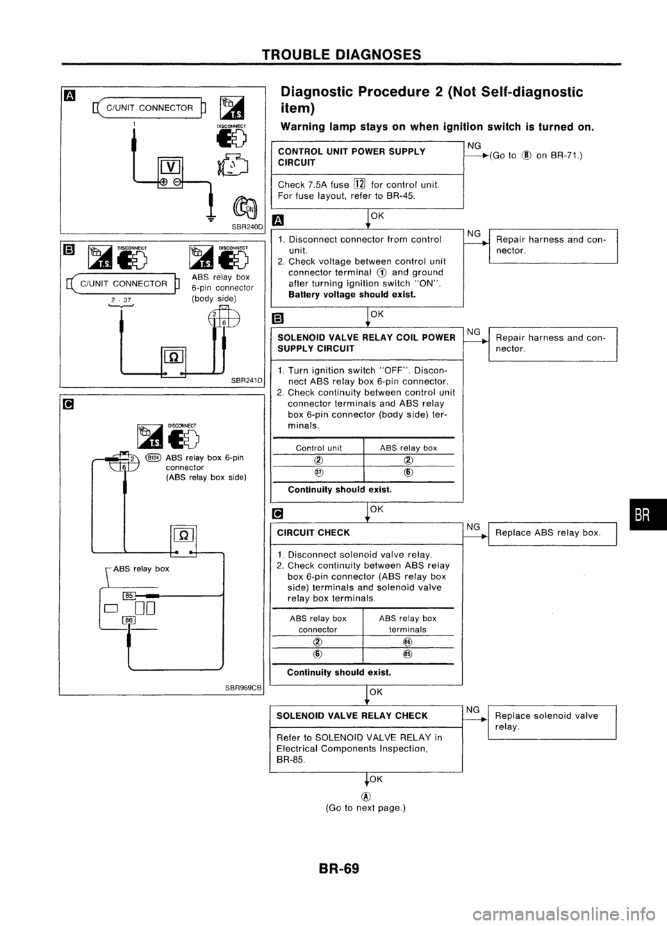
Warning lampstays onwhen ignition switchisturned on.
CONTROL UNITPOWER SUPPLY NG
CIRCUIT ----"""'(Go
to
(!)
onBR-71.)
Check 7.5Afuse
[ll]
forcontrol unit.
For fuse layout, refertoBR-45.
m
OK
1. Disconnect connectorfromcontrol NG
Repair harness andcon-
unit.
----.......
nector.
2. Check voltage between controlunit
connector terminal
(i)
and ground
alter turning ignition switch"ON".
Battery voltage shouldexist.
[;]
~OK
SOLENOID VALVERELAYCOILPOWER NG
Repair harness andcon-
SUPPL YCIRCUIT
----+
nector.
1. Turn ignition switch"OFF". Discon-
nect ABS relay box6-pin connector.
2. Check continuity betweencontrolunit
connector terminalsandABS relay
box 6-pin connector (bodyside)ter-
minals.
Control unit ABS
relay box
@ @
@
CID
Continuity shouldexist.
[!]
~OK
CIRCUIT CHECK
~Replace
ABSrelay box.
1. Disconnect solenoidvalverelay.
2. Check continuity betweenABSrelay
box 6-pin connector (ABSrelay box
side) terminals andsolenoid valve
relay boxterminals.
ABS relay box ASSrelay box
connector terminals
@ @
CID
@
Continuity shouldexist.
OK
SOLENOID VALVERELAYCHECK NG
Replace solenoid valve
~
relay.
Refer toSOLENOID VALVERELAY in
Electrical Components Inspection,
BR-85.
.OK
SBR240D
SBR241D
ASS
relay box
6-pin connector
(body side)
E$B
~i5
~ @)
ABSrelay box6-pin
~ connector
(ABS relayboxside)
(
C/UNIT
CONNECTOR
1
~i5
( C/UNIT CONNECTOR
P
2 .37
'--v--'
@
(Go tonext page.)
BR-69
Page 369 of 1701
CLUTCHDISCANDCLUTCH COVER
~1st: 10-20(1.0-2.0,7.2-14)
2nd: 22-29 (2.2 -3.0 ,16 -22)
ACL019
SEC.
300
o
Clutchdisc
• Do not clean insolvent.
• When installing, becareful thatgrease from
main drive shaft doesnotadhere toclutch disc. Clutch
cover
m
(iJ:
Apply lithium-based greaseincluding
molybdenum disulphide.
~ :N'm (Kg-m, ft-Ib).
•
SCL221 Clutch
Disc
INSPECTION
Check thefollowing items,andreplace ifnecessary.
• Clutch disc,forburns, discoloration, oilorgrease leakage
• Clutch disc,forwear offacing
Wear limitoffacing surface torivet head:
0.3 mm (0.012 in)
• Clutch disc,forbacklash ofspline andrunout offacing.
Maximum backlashofspline (atouter edgeofdisc):
Model 180 0.7mm (0.028 in)
Model 190
and 200 0.8mm (0.031 in)
Model 215 0.9mm(0.035in)
Runout limit:
1.0 mm (0.039 in)
Distance ofrunout checkpoint(from hubcenter):
Model 180
85mm (3.35 in)
Model 190
90mm (3.54 in)
Model 200
95mm (3.74 in)
Model 215102.5mm (4.04in)
CL-11
Page 374 of 1701

CONTENTS(Conl'd.)
Front FogLamp Aiming Adjustment.. 101
Rear FogLamp/Wiring Diagram-R/FOG -102
Turn Signal andHazard Warning Lamps/
Schematic 106
Turn Signal andHazard Warning
Lamps/Wiring Diagram-TURN - 107
Turn Signal andHazard Warning
Lamps/Trouble Diagnoses 113
Combination FlasherUnitCheck 113
Bulb Specifications 114
INTERIOR LAMP 115
Illumination/Schematic 115
Illumination/Wiring Diagram-ILL - 116
Interior, Spot,Trunk Room andLuggage
Room Lamps/Wiring Diagram-INT/L - 122
Bulb Specifications 126
METER ANDGAUGES 127
Combination Meter 127
Speedometer, Tachometer,Temp.andFuel
Gauges/Wiring Diagram-METER - 129
Inspection/Fuel GaugeandWater
Temperature Gauge 133
Inspection/Tachometer 134
Inspection/Speedometer andVehicle Speed
Sensor 135
Fuel Tank Gauge UnitCheck 137
Thermal Transmitter Check 137
Vehicle SpeedSensor SignalCheck 137
WARNING LAMPSANDBUZZER 138
Warning Lamps/Schematic 138
Warning Lamps/Wiring Diagram-WARN -139
Oil Pressure SwitchCheck 151
Fuel Warning LampSensor Check 151
Diode Check 151
Warning BuzzerUnit... 151
Warning Buzzer/System Description 152
Warning Buzzer/Wiring Diagram
- BUZZER - 154
Components Inspection-Warning Buzzer 157
WIPER ANDWASHER 160
Front Wiper andWasher/System Description160
Front Wiper andWasher/Wiring Diagram
- WIPER - 162
Front Wiper Amplifier Check 166
Front Wiper Installation andAdjustment.. 166
Front Wiper Linkage 167
Front Washer NozzleAdjustment... 168
Front Washer TubeLayout 168
Rear Wiper andWasher/System Description169Rear
Wiper andWasher/Wiring Diagram
- WIP/R - 171
Rear Wiper Amplifier Check 175
Rear Wiper Installation andAdjustment.. 175
Rear Washer NozzleAdjustment 175
Rear Washer TubeLayout.. 176
Check Valve(forrear washer) 176
Headlamp WiperandWasher/Wiring Diagram
- HLC - 177
Headlamp WiperMotorCheck 179
Headlamp WiperInstallation 179
Headlamp WasherTubeLayout.. 179
Check Valve(Forheadlamp washer) 179
POWER WINDOW 180
System Description 180
Schematic 183
Wiring Diagram -WINDOW - 185
Trouble Diagnoses 197
POWER DOORLOCK 198
System Description 198
Schematic 200
Wiring Diagram -D/LOCK - 202
Trouble Diagnoses -Type 1(For Europe and
Austral ia) 212
Trouble Diagnoses -Type 2(Except for
Europe andAustralia) 216
POWER DOORMIRROR 220
Wiring Diagram -MIRROR - 220
ELECTRIC SUNROOF 224
Wiring Diagram -SROOF - 224
HORN, CIGARETTE LIGHTERANDCLOCK 226
Wiring Diagram -HORN - 226
REAR WINDOW DEFOGGER ANDDOOR
MIRROR DEFOGGER 230
System Description (Formodels withdaytime
light system) 230
Wirin.g Diagram -DEF - 231
Filament Check 235
Fi lament Repai
r
236
AUDIO ANDANTENNA 237
Audio/System Description 237
Wiring Diagram -AUDIO - 238
Radio FuseCheck 243
Location ofAntenna 243
Antenna RodReplacement.. 243
HEATED SEAT 245
Wiring Diagram -H/SEAT - 245
NATS (Nissan Anti-Theft System) 247
System Description 247
System Composition 247
Page 523 of 1701

Ohmmeter- + WARNING
LAMPSANDBUZZER
Oil Pressure SwitchCheck
Oil pressure
Continuity
kPa (bar, kg/cm
2,
psi)
More than10-20
NO
Engine
start
(0.10-0.20, 0.1-0.2, 1.4-2.8)
Less than10-20
YES
Engine
stop
(0.10-0.20, 0.1-0.2, 1.4-2.8)
SEL748K
Test lamp 3.4WON
\ ,I
"
/
Ballery
Test lamp 3.4W OFF
~0
CD
Ballery
Gasoline MEL623D
SEL901F
Check
thecontinuity betweentheterminals ofoil pressure
switch andbody ground.
Fuel Warning LampSensor Check
• Itwill take ashort timeforthe bulb tolight.
Diode Check
• Check continuity usinganohmmeter.
• Diode isfunctioning properlyiftest results areasshown in
the figure atleft.
NOTE:
Specification mayvary depending onthe type oftester. Before
performing thisinspection, besure torefer tothe instruction
manual forthe tester tobe used.
• Diodes forwarning lampsarebuilt intothecombination
meter printed circuit.
Refer to"Combination Meter"(EL-127).
Warning BuzzerUnit
• Seat beltwarning lampiscontrolled bythe warning buzzer
unit.
Refer to"Warning Buzzer"(EL-152).
EL-151
•
Page 607 of 1701
REARWINDOW DEFOGGER ANDDOOR MIRROR DEFOGGER
[+1
6 volts (normal filament)
[-1
SEL263 Filament
Check
1. Attach probecircuit tester(involt range) tomiddle portion
of each filament.
SEL 122R
Burned outpoint
12 volts
•
When measuring voltage,wraptinfoil around thetop ofthe
negative probe.Thenpress thefoil against thewire with
your finger.
2. Ifa filament isburned out,circuit testerregisters 0or 12
volts.
[+1
[-]
o
volts
SEL265
SEL266
3.
To locate burned outpoint, moveprobe alongfilament.
Tester needle willswing abruptly whenprobe passes the
point.
EL-235
•
Page 684 of 1701
PRECAUTIONSANDPREPARATION
Precautions
• When installing rubberparts,finaltightening mustbecar-
ried outunder unladen condition* withtires onground.
*: Fuel, radiator coolantandengine oilfull. Spare tire,
jack,
hand tools andmats indesignated positions.
• After installing removedsuspension parts,check wheel
alignment andadjust ifnecessary.
• Use flare nutwrench whenremoving orinstalling brake
tubes.
• Always torquebrakelineswhen installing.
Tool number
Tool name
SBR820B
Special Service Tools
Description
HT72520000
Ball joint remover Removing
tie-rodouterendandlower ball
joint
NT146
HT71780000
Spring compressor
ST35652000
Strut attachment
NT144
Removing
andinstalling coilspring
Fixing strutassembly
NT145
GG94310000
Flare nuttorque wrench
KV38106700
KV381 06800
Differential sideoilseal
protector
NT406
NT147
FA-2
Removing
andinstalling brakepiping
a:
10mm (0.39 in)
Installing driveshaft
LH: KV38106700
RH: KV38106800