Page 97 of 1701
REPAIRFORCOMPONENT PARTS
High Clutch
SEC. 315
Fa< th.oumh" of,Iuloh ,h.of. (d".,pI".... dd,I ...
PI'@(if)
,,',' to
fh'
"'ow
010.... ""00. ~)~
Driven
plate
Retaining plate* Input
shaft assembly
(High clutch drum)
Except model34X81
Snap ring
f:1
m
@•
Apply petroleum jelly.
@.
ApplyATF
* ;Select proper thickness. Retaining
Snap ring
l
Driven
plate
-- Drive plate Retaining
plate*-
Model
34X81
Driven
plate
1.5
mm
(0.059
in)
Driven plate
i
2.0
mm
•.•. (0.079
in)
SAT0841
•
Nylon cloth
SAT176D
Input shaft
1/5'"
hog
SAT177D DISASSEMBLY
1. Check operation ofhigh clutch.
a. Apply compressed airtooil hole ofinput shaft.
• Stop upahole onopposite sideofinput shaft.
b. Check tosee that retaining platemoves tosnap ring.
c. Ifretaining platedoesnotcontact snapring,
• O-ring mightbedamaged.
• Oilseal might bedamaged.
• Fluid might beleaking pastpiston checkball.
2. Remove sealrings frominput shaft.
AT-97
Page 98 of 1701
Snapring,
REPAIR
FORCOMPONENT PARTS
High Clutch (Cont'd)
3. Remove snapring.
4. Remove driveplates, drivenplatesandretaining plate.
SAT178D
5.Set Tool onspring retainer andremove snapringfrom high
clutch drumwhile compressing returnsprings.
• Set Tool directly abovesprings.
• Donot expand snap
ring
excessively.
6. Remove springretainer andreturn springs.
• Donot remove returnsprings fromspring retainer.
SAT617H
7.Remove pistonfromhighclutch drumbyturning it.
8. Remove O-ringandoilseal from piston.
SAT139E INSPECTION
Reverse clutchsnapring,spring retainer andreturn
springs
• Check fordeformation, fatigueordamage.
• Replace ifnecessary.
• When replacing springretainer andreturn springs, replace
them asaset.
AT-98
Page 99 of 1701

•
Seal
ringclearance
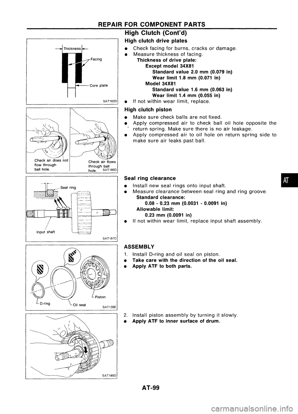
• Install newseal rings ontoinput shaft.
• Measure clearance betweensealringandring groove.
Standard clearance:
0.08 -0.23 mm(0.0031 -0.0091 in)
Allowable limit:
0.23 mm(0.0091 in)
• If
not within wearlimit,replace inputshaftassembly.
REPAIR
FORCOMPONENT PARTS
High Clutch (Cont'd)
High clutch driveplates
• Check facingforburns, cracks ordamage.
• Measure thickness offacing.
Thickness ofdrive plate:
Except model34X81
Standard value2.0mm (0.079 in)
Wear limit1.8mm (0.071 in)
Model 34X81
Standard value1.6mm (0.063 in)
Wear limit1.4mm (0.055 in)
SAT162D •
Ifnot within wearlimit,replace.
High clutch piston
• Make surecheck ballsarenotfixed.
• Apply compressed airtocheck balloilhole opposite the
return spring. Makesurethere isno air leakage.
• Apply compressed airtooil hole onreturn spring sideto
make sureairleaks pastball.
Facing
Core plate
Check airflows
through ball
hole. SAT186D
Input shaft
I
I
Check airdoes not
flow through
ball hole.
SAT187D
ASSEMBLY
1. Install O-ringandoilseal onpiston.
• Take carewiththedirection ofthe oilseal.
• Apply ATFtoboth parts.
2. Install pistonassembly byturning itslowly.
• Apply ATFtoinner surface ofdrum.
AT-99
Page 102 of 1701
andOverrun Clutch
REPAIR
FORCOMPONENT
Forward Clutch PARTS
Spring retainer Overrun
clutch
piston
CD
Snap ring
~ Retaining plate
*
~ Drive plate
o
Driven plate
CID
Dish plate
Oilseal~~
.~
* :
Select
@D:
Applyx~~per thickness.
SAT942HA
DISASSEMBLY
1. Check operat'
~: ~;t~" bearin~o~e~~i~:;ard clutchandov
c. Ch~:k ~ompressed airt~n forward ciutch,;;run clutch.
o see that
011
hole off rum.
retaining plateorwardclutchd
. movestos rum.
nap ring.
Bearing
retainer
•
• •
If
r~taining plated
D~nng mightboesnotconta
0,1
seal m"hedamaged ctsnap ring
F
ig
t
b d' '
luid might beamaged
e leak' '
mg past piston ch
eck ball.
AT.102
Page 104 of 1701

SAT140E
REPAIR
FORCOMPONENT PARTS
Forward ClutchandOverrun Clutch(Cont'd)
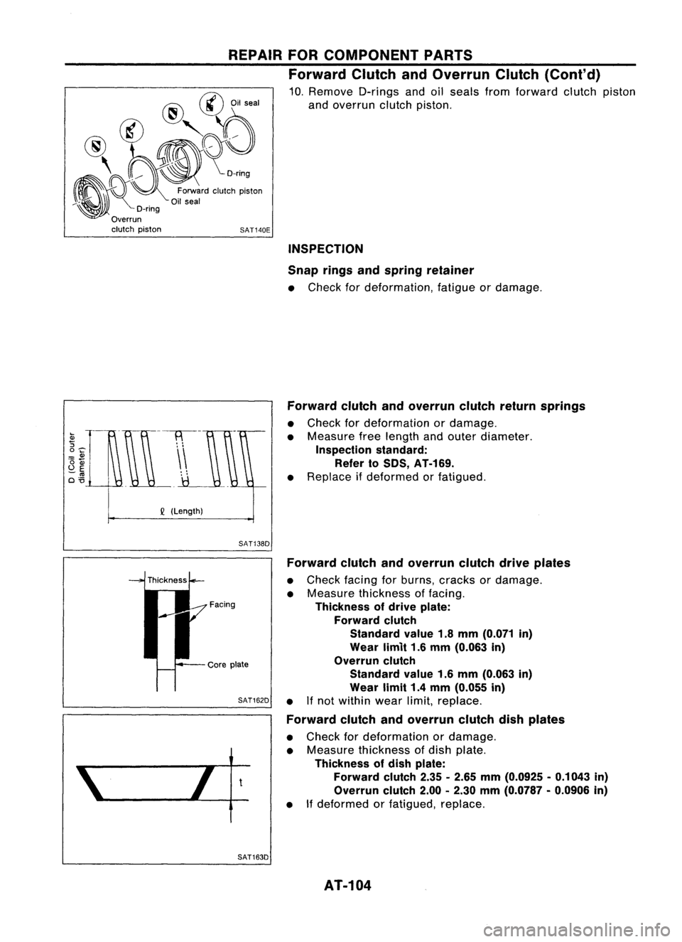
10. Remove D-ringsandoilseals fromforward clutchpiston
and overrun clutchpiston.
@
@
Oilseal
@
@'r:rY;)
, ~~o
~~o:~::'"
"'Ioh
pi","
l\~)t
D-rlng
Overrun clutch piston
INSPECTION
Snap ringsandspring retainer
• Check fordeformation, fatigueordamage.
Forward clutchandoverrun clutchreturnsprings
• Check fordeformation ordamage.
• Measure freelength andouter diameter.
Inspection standard:
Refer toSOS, AT-169.
• Replace ifdeformed orfatigued.
Q
(Length)
SAT138D
Facing
Core plate
SAT162D
t
Forward
clutchandoverrun clutchdriveplates
• Check facingforburns, cracks ordamage.
• Measure thickness offacing.
Thickness ofdrive plate:
Forward clutch
Standard value1.8mm (0.071 in)
Wear limit1.6mm (0.063 in)
Overrun clutch
Standard value1.6mm (0.063 in)
Wear limit1.4mm (0.055 in)
• Ifnot within wearlimit,replace.
Forward clutchandoverrun clutchdishplates
• Check fordeformation ordamage.
• Measure thickness ofdish plate.
Thickness ofdish plate:
Forward clutch2.35-2.65 mm(0.0925 -0.1043 in)
Overrun clutch2.00-2.30 mm(0.0787 -0.0906 in)
• Ifdeformed orfatigued, replace.
SAT163D AT-104
Page 105 of 1701

Checkairdoes notflow
through ballhole. REPAIR
FORCOMPONENT PARTS
Forward ClutchandOverrun Clutch(Cont'd)
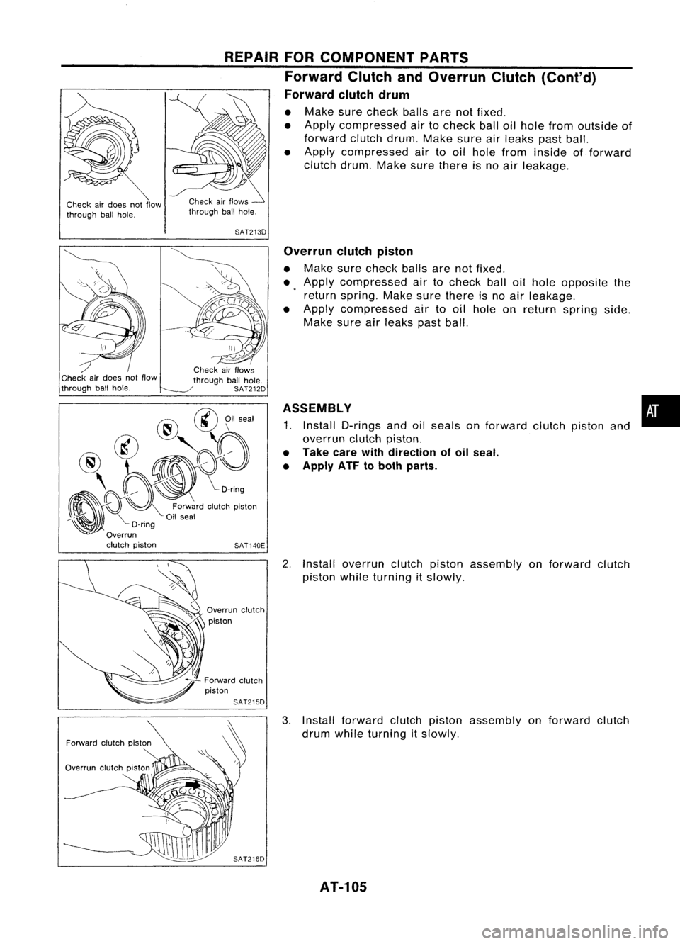
Forward clutchdrum
• Make surecheck ballsarenotfixed.
• Apply compressed airtocheck balloilhole from outside of
forward clutchdrum.Makesureairleaks pastball.
• Apply compressed airtooil hole from inside offorward
clutch drum.Makesurethere isno air leakage.
SAT213D
@ @Oilseal
@,~~~
~ O;',':'doI"toh
pi","
~'U,.,
O-nng
Overrun
clutch piston SAT140EOverrun
clutchpiston
• Make surecheck ballsarenotfixed.
• Apply compressed airtocheck balloilhole opposite the
return spring. Makesurethere isno air leakage.
• Apply compressed airtooil hole onreturn spring side.
Make sureairleaks pastball.
pistonand.
ASSEMBLY
1. Install O-rings andoilseals onforward clutch
overrun clutchpiston.
• Take carewithdirection ofoil seal.
• Apply ATF toboth parts.
Check
airflows
through ballhole.
SAT212D
Check
airdoes notflow
through ballhole.
Overrunclutch
piston
2.
Install overrun clutchpiston assembly onforward clutch
piston whileturning itslowly.
3. Install forward clutchpiston assembly onforward clutch
drum while turning itslowly.
AT-105
Page 108 of 1701
REPAIRFOR
COMPONENT PARTS
Low
&
Reverse Brake
SAT943HA
Dish
plate
Drive
plate
Retaining
plate
*
Driven plate
Retaining plate
Driven plate
Drive
plate
* :
Select
~: Applyx~~per thickness.
SEC.
315
For the numb
refer tothe b:~O~ clutch sheets (dri
cross-section
veplates anddI
,
rven plates),
DISASSEMBL Y
1. Check operat'
a. Apply co Ionoflow
&
r
b. Check tmpressed airtoo,el vherse brake
c If
0
see that
I
ole oft .
. retaining platdretaining plateransmission ca
• D-rin .eoes n
t
moves
t
se.
• Oil gmight bedama
0
contact snap
.0
snap ring.
seal might
be
ged. ring,
• FluId might bdamaged
e leak' .
Ing past piston h
c eck ball
2. Stand trans .,
3. Remove sn~l1IS~lOn case.
4. Remov .p nng.
d' ednve plate
Ish plates fromts,~riven plate
ransmlssio s,
n case. retaining
platesand
AT-108
Page 109 of 1701
REPAIRFORCOMPONENT PARTS
Low
&
Reverse Brake(Conl'd)
5. Set Tool onspring retainer andremove snapringwhile
compressing returnsprings.
• Set Tool directly abovereturnsprings.
• Donot expand snapringexcessively.
6. Remove springretainer andreturn springs.
• Donot remove returnsprings fromspring retainer.
7. Apply compressed airtooil hole oftransmission casewhile
holding piston.
8. Remove pistonfromtransmission case
by
turning it.
9. Remove D-ringandoilseal from piston.
piston
SAT618H
INSPECTION
Low
&
reverse clutchsnapring,spring retainer and
return springs
• Check fordeformation, fatigueordamage.
• Replace ifnecessary.
• When replacing springretainer andreturn springs, replace
them asaset.
AT-109
•