Page 110 of 1701
REPAIRFORCOMPONENT PARTS
Low
&
Reverse Brake(Coni'd)
Low &reverse brakedriveplate
• Check facing forburns, cracks ordamage.
• Measure thickness offacing.
Facing Thicknessofdrive plate:
Standard value2.0mm (0.079 in)
Wear limit1.8mm (0.071 in)
• Ifnot within wearlimit,replace.
SAT162D Low
&
reverse brakedishplates
• Check fordeformation ordamage.
• Measure thickness ofdish plate.
Thickness ofdish plate:
3.00 -3.30 mm(0.1181 -0.1299 in)
• If
deformed orfatigued, replace.
SAT163D ASSEMBLY
1. Install D-ring andoilseal onpiston.
• Take carewiththedirection ofthe oilseal.
• Apply ATFtoO-ring andoilseal.
2. Stand transmission case.
3. Install piston assembly ontransmission casewhile turning
it slowly.
• Apply ATFtoinner surface oftransmission case.
4. Install returnsprings andspring retainer onpiston.
AT-110
Page 157 of 1701
SAT397D
Straightedge SAT695D
SAT696D ASSEMBLY
11. Apply compressed airtooil holes oftransmission caseand
check operation ofbrake band.
Adjustment 3
FINAL DRIVE ENDPLAY
_. Except model34X81-
• Measure clearance betweendifferential sidebearing and
transmission case.
• Select proper thickness ofadjusting shimsothat end play
is within specifications.
1. Measure dimension 'T"between sidebearing fittingsur-•
face oftransmission caseandconverter housingfittingsur-
face oftransmission case.
"T/':
indication ofgauge
2. Measure thickness ofstraightedge "t".
T
= T
1 -
t
3. Place finaldrive assembly onconverter housing.
4. Measure dimension "U"between endofdifferential case
and transmission casefitting surface ofconverter housing.
AT-157
Page 159 of 1701
3-5 (0.12 •0.20)
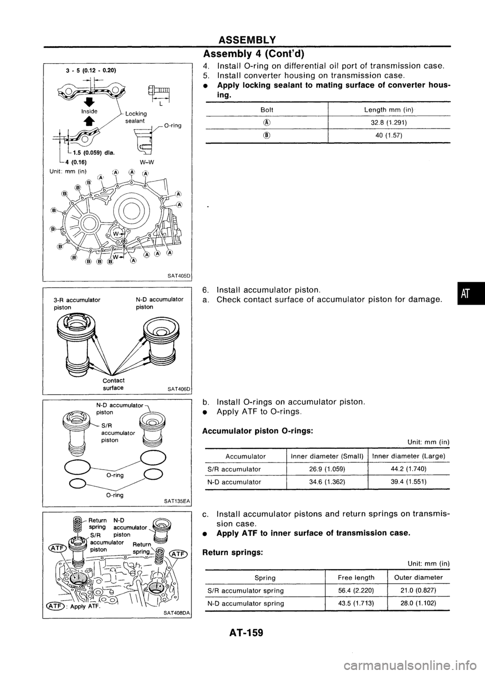
6.Install accumulator piston.
a. Check contact surface ofaccumulator pistonfordamage.
ASSEMBLY
Assembly 4(Cont'd)
4. Install a-ring ondifferential oilport oftransmission case.
5. Install converter housingontransmission case.
• Apply locking sealant tomating surface ofconverter hous-
ing.
•
Length
mm(in)
32.8 (1.291)
40 (1.57)
@
@
Bolt
SAT405D
w-w
N-D accumulator
piston
Locking
sealant
~O'i"9
3-R accumulator
piston
Unit:
Contactsurface
SAT406D
N-D accumUlato'e
~iston ~
SIR ~
accumulator
piston
o
~C)
O~
O-ring
b.
Install a-rings onaccumulator piston.
• Apply ATFtoa-rings.
Accumulator pistonO-rings:
Unit:mm(in)
Accumulator Inner
diameter (Small) Inner
diameter (Large)
SIR
accumulator
26.9
(1.059) 44.2
(1.740)
N-D accumulator
34.6
(1.362) 39.4
(1.551)
SAT135EA
~ Return N-D ~
~ spring accumulator ~
~S/R piston
@)
accumulator Return
ATF .
t
pIS on spring~
tATi="
~~ ~~'\\~
~~U~~~-1C .....~.~ ..
}~y)~:
° ~~~'
o*lf
_~o_
00\\
II~o
~: ApplyATF.
r
c.
Install accumulator pistonsandreturn springs ontransmis-
sion case.
• Apply ATFtoinner surface oftransmission case.
Return springs:
Unit:mm(in)
Spring Free
length Outer
diameter
SIR
accumulator spring
56.4
(2.220) 21.0
(0.827)
N-D accumulator spring
43.5
(1.713) 28.0(1.102)
SAT408DA
AT-159
Page 225 of 1701
BODYEND
Body Front End
• When removing orinstalling hood,placeacloth orother padding onhood. Thisprevents vehiclebody
from being scratched.
• Bumper fasciaismade ofplastic. Donot use excessive forceandbesure tokeep oilaway fromit.
• Hood adjustment: Adjustathinge portion.
• Hood lockadjustment: Afteradjusting, checkhoodlockcontrol operation. Applyacoat ofgrease to
hood locks engaging mechanism.
• Hood opener: Donot attempt tobend cable forcibly. Doingsoincreases effortrequired tounlock
hood.
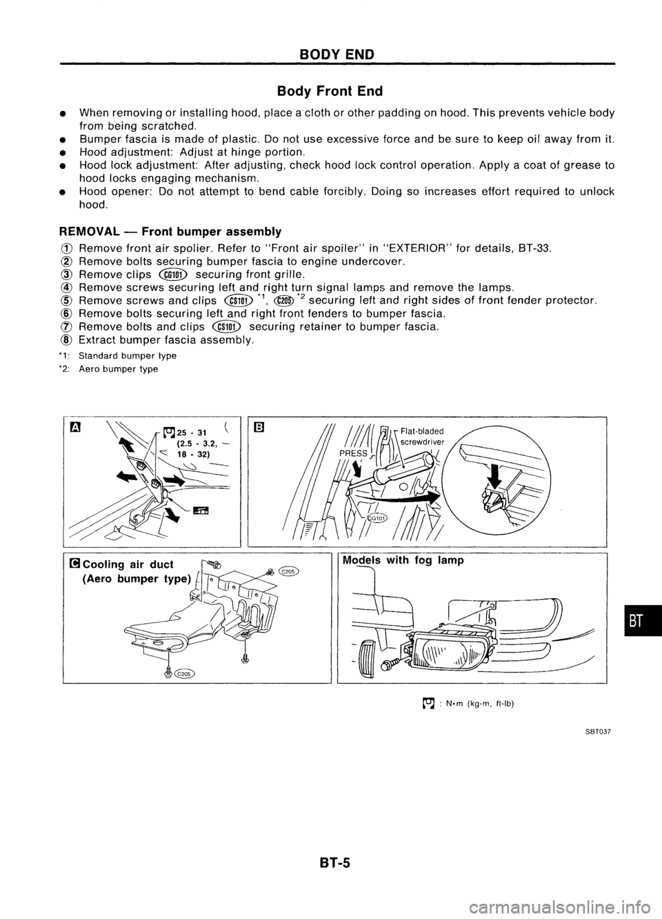
REMOVAL -Front bumper assembly
CD
Remove frontairspolier. Referto"Front
air
spoiler" in"EXTERIOR" fordetails, BT-33.
@
Remove boltssecuring bumperfasciatoengine undercover.
CID
Remove clips
@QD
securing frontgrille.
@
Remove screwssecuring leftand right turnsignal lampsandremove thelamps.
@
Remove screwsandclips
@W
*1,
@
*2
securing
leftand right sides offront fender protector.
@)
Remove boltssecuring leftand right front fenders tobumper fascia.
([) Remove boltsandclips
@W
securing retainertobumper fascia.
@)
Extract bumper fasciaassembly.
*1: Standard bumpertype
*2: Aero bumper type
to.J:
N'm (kg-m, ft-Ib)
SBT037
B1-5
•
Page 227 of 1701
BODYEND
Body RearEndandOpener
4-DOOR SEDAN
• When removing orinstalling trunklid,place acloth orother padding onrear fender. Thisprevents
vehicle bodyfrombeing scratched.
• Bumper fasciaismade ofplastic. Donot use excessive forceandbesure tokeep oilaway fromit.
• Trunk lidadjustment: Adjustathinge-trunk lidportion forproper trunklidfit.
• Trunk lidlock system adjustment: Adjuststriker sothat itis inthe center ofthe lock. After
adjustment, checktrunklidlock operation.
• Opener cable:Donot attempt tobend cable usingexcessive force.
• After installation, makesurethattrunk lidand fuel filler lidopen smoothly.
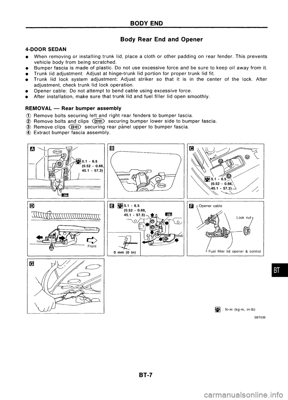
REMOVAL -Rear bumper assembly
CD
Remove boltssecuring leHand right rearfenders tobumper fascia.
@
Remove boltsandclips
@ID
securing bumperlowersidetobumper fascia.
@
Remove clips
@ID
securing rearpimel upper tobumper fascia.
@
Extract bumper fasciaassembly.
rn
'11IInff\
\W,\\CC\\\\\\\\\\\\\\
[;I
~5.1 .6.5
(;I
(0.52 •0.66,
45.1 -57.3)~n
m
__ \.QL_OIT~~T~
Jf-~~
o
mm
(0
in)
B1-7 Fuel
fillerlidopener &control
~ :N'm (kg-m, in-Ib)
SBT039
•
Page 275 of 1701
CHECKANDADJUSTMENT
OK
MINMax.
line
Min. line
SBR418C
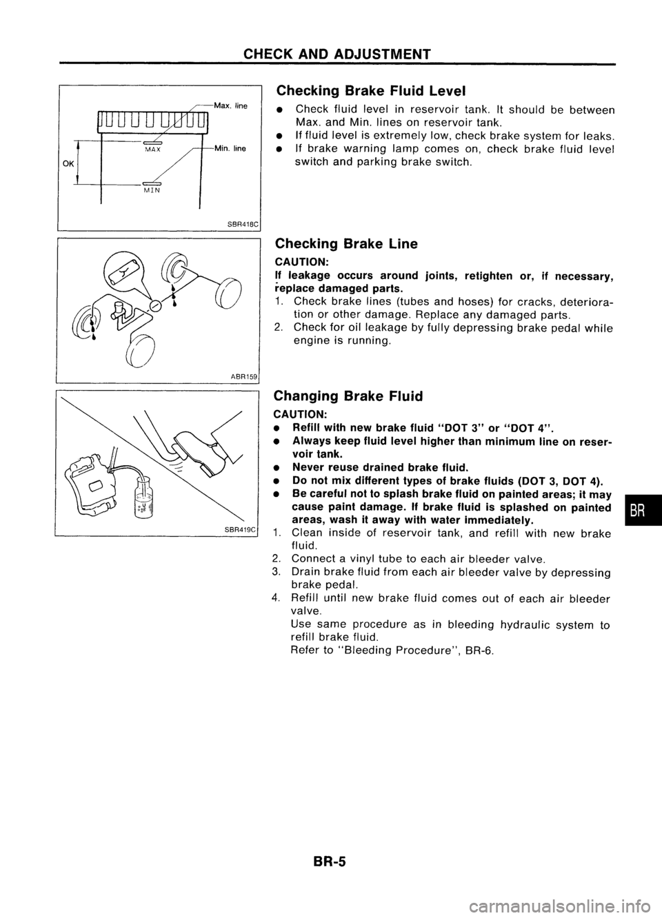
Checking
BrakeFluidLevel
• Check fluidlevel inreservoir tank.Itshould bebetween
Max. andMin. lines onreservoir tank.
• Iffluid level isextremely low,check brakesystem forleaks.
• Ifbrake warning lampcomes on,check brakefluidlevel
switch andparking brakeswitch.
ABR159
SBR419C
Checking
BrakeLine
CAUTION: If leakage occursaround joints,retighten or,ifnecessary,
replace damaged parts.
1. Check brakelines(tubes andhoses) forcracks, deteriora-
tion orother damage. Replaceanydamaged parts.
2. Check foroilleakage byfully depressing brakepedalwhile
engine isrunning.
Changing BrakeFluid
CAUTION:
• Refill withnewbrake fluid"DOT 3"or"DOT 4".
• Always keepfluidlevel higher thanminimum lineonreser-
voir tank.
• Never reusedrained brakefluid.
• Donot mix different typesofbrake fluids(DOT3,DOT 4).
• Becareful nottosplash brakefluidonpainted areas;itmay •
cause paintdamage. Ifbrake fluidissplashed onpainted :•
areas, washitaway withwater immediately.
1. Clean inside ofreservoir tank,andrefill withnewbrake
fluid.
2. Connect avinyl tubetoeach airbleeder valve.
3. Drain brake fluidfrom each airbleeder valvebydepressing
brake pedal.
4. Refill untilnewbrake fluidcomes outofeach airbleeder
valve.
Use same procedure asinbleeding hydraulic systemto
refill brake fluid.
Refer to"Bleeding Procedure", BR-6.
BR-5
Page 282 of 1701
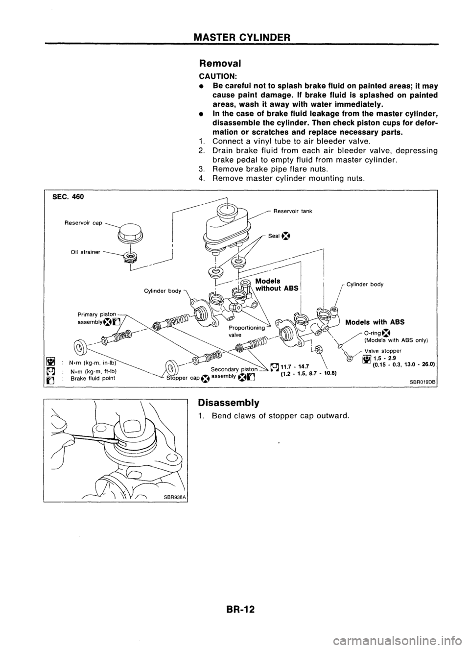
MASTERCYLINDER
Removal
CAUTION:
• Becareful nottosplash brakefluidonpainted areas;itmay
cause paintdamage. Ifbrake fluidissplashed onpainted
areas, washitaway withwater immediately.
• Inthe case ofbrake fluidleakage fromthemaster cylinder,
disassemble thecylinder. Thencheck piston cupsfordefor-
mation orscratches andreplace necessary parts.
1. Connect avinyl tubetoair bleeder valve.
2. Drain brake fluidfrom each airbleeder valve,depressing
brake pedaltoempty fluidfrom master cylinder.
3. Remove brakepipeflare nuts.
4. Remove mastercylinder mounting nuts.
Models withASS
/O-ring~
'V
(ModelswithABS only)
'\~ /'Valve stopper
T@" ~
1.5.2.9
(0.15.0.3, 13.0•26.0)
o
l-~
~ 11.7 -14.7 \
(1.2 -1.5, 8.7-10.8)
SBR019DB
Seal~
___
Reservoir tank
jJ'JD~----
~ ..-:'J
C'9 ---
Secondarypiston
Stopper cap~assembly
~f]
Cylinder
body
N.m (kg-m, in-Ib)
N.m (kg-m. ft-Ib)
Brake fluidpoint
Reservoir
cap
----g
Oil strainer ----. ~
L------- -
SEC.
460
Disassembly
1. Bend claws ofstopper capoutward.
BR-12
Page 287 of 1701
SBR225B
----a
MoreIh.. 24mm
(0.94 In)
----------r:~
---------~~~----------
Connect hoseuntilitcontacts
protrusion onvacuum tube.
VACUUM
HOSE
Removal andInstallation
CAUTION:
When installing vacuumhoses,payattention tothe following
points.
• Donot apply anyoilorlubricants tovacuum hoseandcheck
valve.
• Insert vacuum tubeintovacuum hoseasshown.
• Install checkvalve, paying attention toits direction.
TYPE 1
Intake manifold Brakebooster
; C::::::::'::::~:d
q
SBR498A
CAUTION
~
... ENG. TYPE
2
Inspection
HOSES ANDCONNECTORS
Check vacuum lines,connections andcheck valvefor
airtightness, improperattachment, chafinganddeterioration.
BR-17
•