Page 1023 of 1701
Repairharness orcon-
nectors.
Replace resistor.
NG
NG
CHECK COMPONENT
(Resistor).
Refer to"COMPONENT INSPECTION"
on next page.
CHECK
INPUTSIGNAL CIRCUIT.
1. Stop engine.
2. Disconnect ignitioncoilharness con-
nector.
3. Strip tapecovering resistor.
4. Disconnect ECMharness connector.
5. Check harness continuity between
ignition coilterminal
CID
and resistor
terminal
(!).
resistor terminal
@
and ECM terminal
@.
Continuity shouldexist.
If OK, check harness forshort.
OK
TROUBLE
DIAGNOSIS FORDTC21
Ignition Signal(Cont'd)
@
SEF471Q
(;J~i5
~i5
1
~~Q~
'Cf~OONNlliOR~
LllJ
~i5
cffu
[ill
Disconnectandreconnect harnesscon-
nectors inthe circuit. Thenretest.
Trouble isnot fixed.
Check ECMpinterminals fordamage
and check theconnection ofECM har-
ness connector. Reconnect ECMhar-
ness connector andretest.
INSPECTION END
EC-304
Page 1024 of 1701
•
Approximately
25kQ
Resistance
[at25'C (77'F)]
0.5 -1.0Q
Terminal
(J) -@
(Primary coil)
(J) -
@
(Secondary coil)
For checking secondary coil,remove distributor capand
measure resistance betweencoiltower metaltip
@
and
terminal
(f).
If NG, replace distributor assemblyasaunit.
Ignition
coil
1. Disconnect ignitioncoilharness connector.
2. Check resistance asshown inthe figure.
AEC902
MEC719B
TROUBLE
DIAGNOSIS FORDTC21
Ignition Signal(Cont'd)
COMPONENT INSPECTION
LCoiltower meta/tip
Powertransistor
1. Disconnect camshaftpositionsensor
&
power transistor
harness connector andignition coilharness connector.
2. Check power transistor resistance betweenterminals
CID
and
@.
Terminals Resistance
Result
NotOQ
OK
@
and
@
on
NG
If NG, replace distributor assembly.
Resistor
1. Disconnect resistorharness connector.
2. Check resistance betweenterminals
CD
and
CID
Resistance:
Approximately
2.2kQ
[at
25°C (77°F»
If NG, replace resistor.
EC-305
Page 1044 of 1701

•
INSPECTION END
Check thefollowing.
• Harness connectors
@,@
• Harness connectors
@,
• Harness foropen or
short between injector
and ignition switch
If NG, repair harness or
connectors.
OK
NG
OK
@
INSPECTION
START
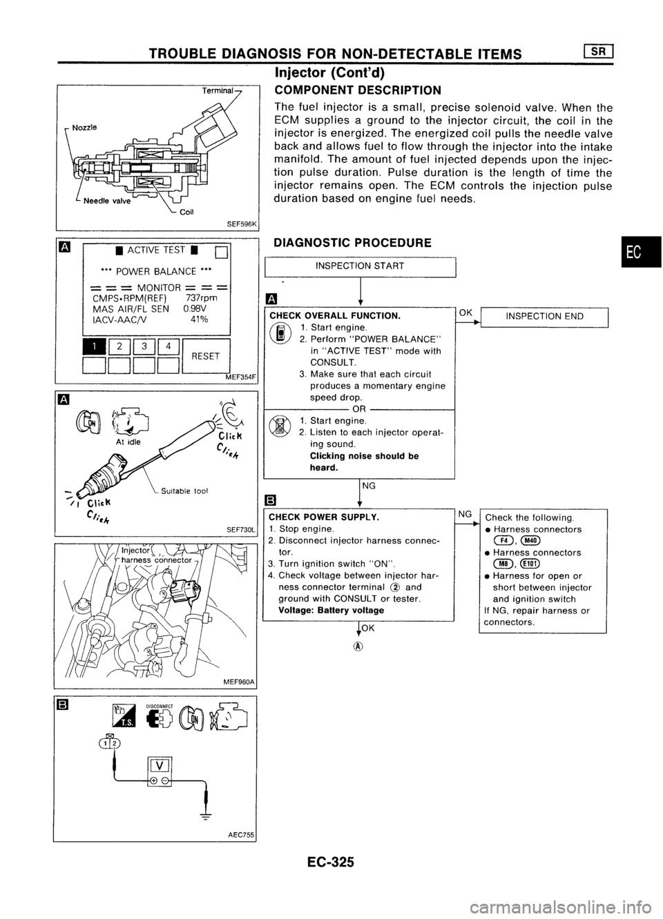
DIAGNOSTIC
PROCEDURE
CHECK OVERALL FUNCTION.
(ij\
1.Start engine.
~ 2.Perform "POWER BALANCE"
in "ACTIVE TEST"modewith
CONSULT.
3. Make surethateach circuit
produces amomentary engine
speed drop.
OR
~ 1.Start engine.
~ 2.Listen toeach injector operat-
ing sound.
Clicking noiseshould be
heard.
CHECK POWER SUPPLY.
SEF730L
1.Stop engine.
2. Disconnect injectorharness connec-
tor.
3. Turn ignition switch"ON".
4. Check voltage between injectorhar-
ness connector terminal
@
and
ground withCONSULT ortester.
Voltage: Batteryvoltage
SEF596K
I~~
Click
Ct.
I~-+
TROUBLE
DIAGNOSIS FORNON-DETECTABLE ITEMS
Injector
{Cont'd)
COMPONENT DESCRIPTION
The fuel injector isasmall, precise solenoid valve.Whenthe
ECM supplies aground tothe injector circuit,thecoil inthe
injector isenergized. Theenergized coilpulls theneedle valve
back andallows fueltoflow through theinjector intotheintake
manifold. Theamount offuel injected depends upontheinjec-
tion pulse duration. Pulseduration isthe length oftime the
injector remains open.TheECM controls theinjection pulse
duration basedonengine fuelneeds.
• ACTIVE TEST.
0
••• POWER BALANCE •••
= ==
MONITOR
=
=
=
CMPS.RPM(REF) 737rpm
MAS AIR/FL SENO.98V
IACV-AACjV 41%
110Q]~~
DDDDL:::J
MEF354F
--
/1
MEF960AAEC755 EC-325
Page 1074 of 1701

MEC730B
•
INSPECTION
START
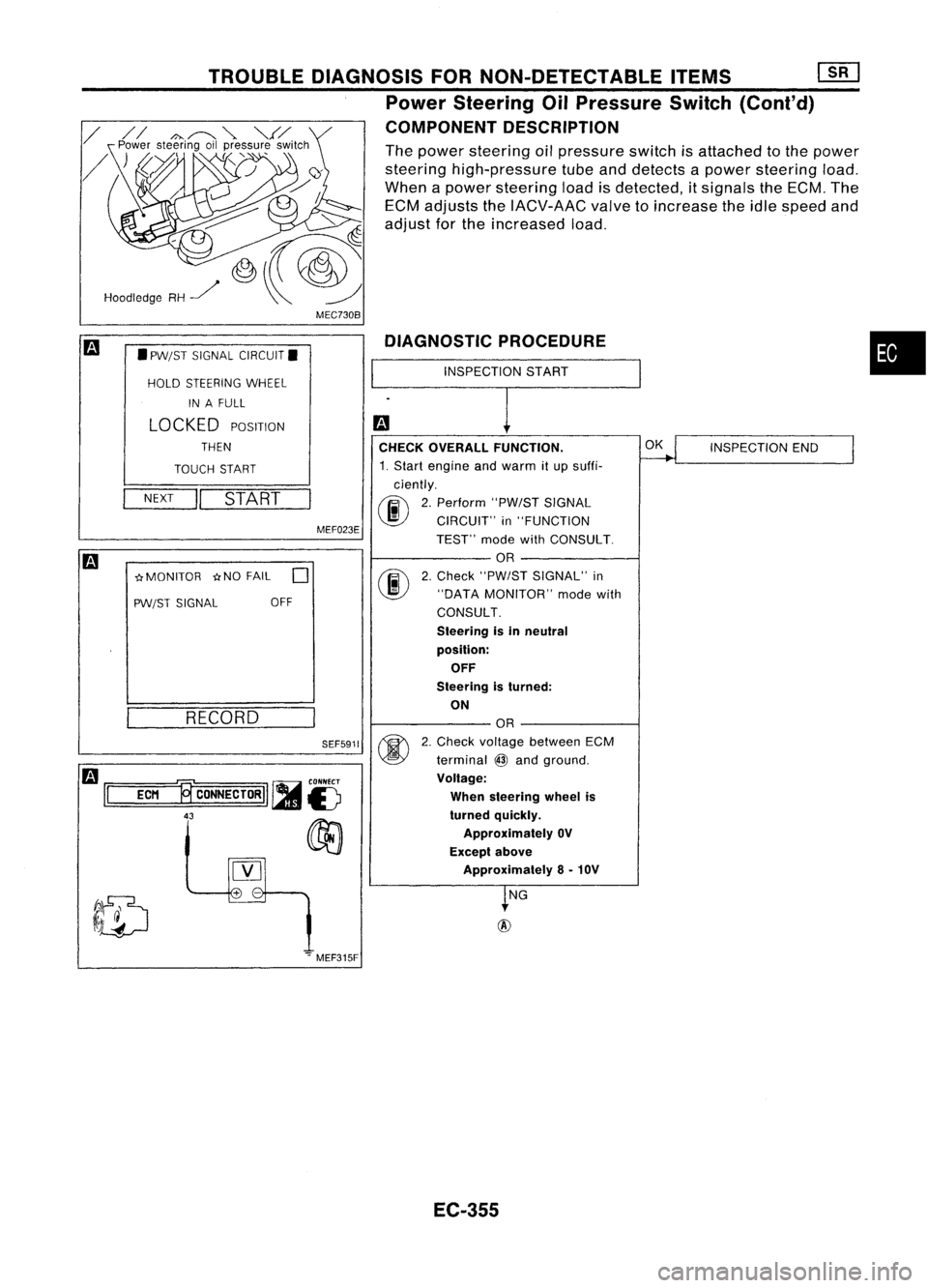
DIAGNOSTIC
PROCEDURE
CHECK OVERALL FUNCTION.
~
INSPECTION
END
I
1. Start engine andwarm itup suffi-
ciently.
00
2.
Perform "PW/STSIGNAL
CIRCUIT" in"FUNCTION
TEST" modewithCONSULT.
OR
@
2.
Check "PW/ST SIGNAL" in
"DATA MONITOR" modewith
CONSULT.
Steering isin neutral
position: OFF
Steering isturned:
ON
OR
@
2.
Check voltage between ECM
terminal
@
and ground.
Voltage:
When steering wheelis
turned quickly.
Approximately OV
Except above
Approximately 8-10V
~NG
+
-
SEF5911
MEF023E
TROUBLE
DIAGNOSIS FORNON-DETECTABLE ITEMS[][]
Power Steering OilPressure Switch(Cont'd)
COMPONENT DESCRIPTION
The power steering oilpressure switchisattached tothe power
steering high-pressure tubeanddetects apower steering load.
When apower steering loadisdetected, itsignals theECM. The
ECM adjusts theIACV-AAC valvetoincrease theidle speed and
adjust forthe increased load.
RECORD
NEXT
II
START
•
PW/ST SIGNAL CIRCUIT.
HOLD STEERING WHEEL
IN AFULL
LOCKED
POSITION
THEN
TOUCH START
-crMONITOR -crNOFAIL
0
PW/ST SIGNAL OFF
Hoodledge
RH~
m
1='
=EC=M
=.,~
CONNECTORII ~
is
43
00
[Y]
.".MEF315F
EC-355
Page 1075 of 1701

TROUBLEDIAGNOSIS FORNON-DETECTABLE ITEMS
mJ
Power Steering OilPressure Switch
(Cont'd)
~i5
dIb
~i5
II
ECM
~CONNECTORII
43 AEC760
SEF501Q
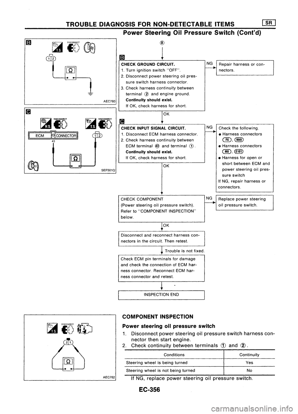
@
1
CHECK GROUND CIRCUIT. NG
Repair harness orcon-
1. Turn ignition switch"OFF".
--..
nectors.
2. Disconnect powersteering oilpres-
sure switch harness connector.
3. Check harness continuity between
terminal
@
and engine ground.
Continuity shouldexist.
If OK, check harness forshort.
OK
[!J
CHECK INPUTSIGNAL CIRCUIT. NG
Check thefollowing.
1. Disconnect ECMharness connector.
--..
•Harness connectors
2. Check harness continuity between
CID,@
ECM terminal
@
and terminal
CD.
•
Harness connectors
Continuity shouldexist.
@,@D
If OK, check harness forshort. •
Harness foropen or
OK short
between ECMand
power steering oilpres-
sure switch
If NG, repair harness or
connectors.
Power steering oilpressure switch
1. Disconnect powersteering oilpressure switchharness con-
nector thenstart engine.
2. Check continuity betweenterminals
CD
and
@.
~
to
ID
~
CHECK
COMPONENT
(Power steering oilpressure switch).
Refer to"COMPONENT INSPECTION"
below.
OK
Disconnect andreconnect harnesscon-
nectors inthe circuit. Thenretest.
Trouble isnot fixed.
Check ECMpinterminals fordamage
and check theconnection ofECM har-
ness connector. ReconnectECMhar-
ness connector andretest.
INSPECTION END
COMPONENT INSPECTION
Conditions
Steering wheelisbeing turned
Steering wheelisnot being turned NG
Replace powersteering
oil pressure switch.
Continuity
Yes
No
AEC762
IfNG, replace powersteering oilpressure switch.
EC-356
Page 1096 of 1701

SEF830INJECTION
NOZZLE
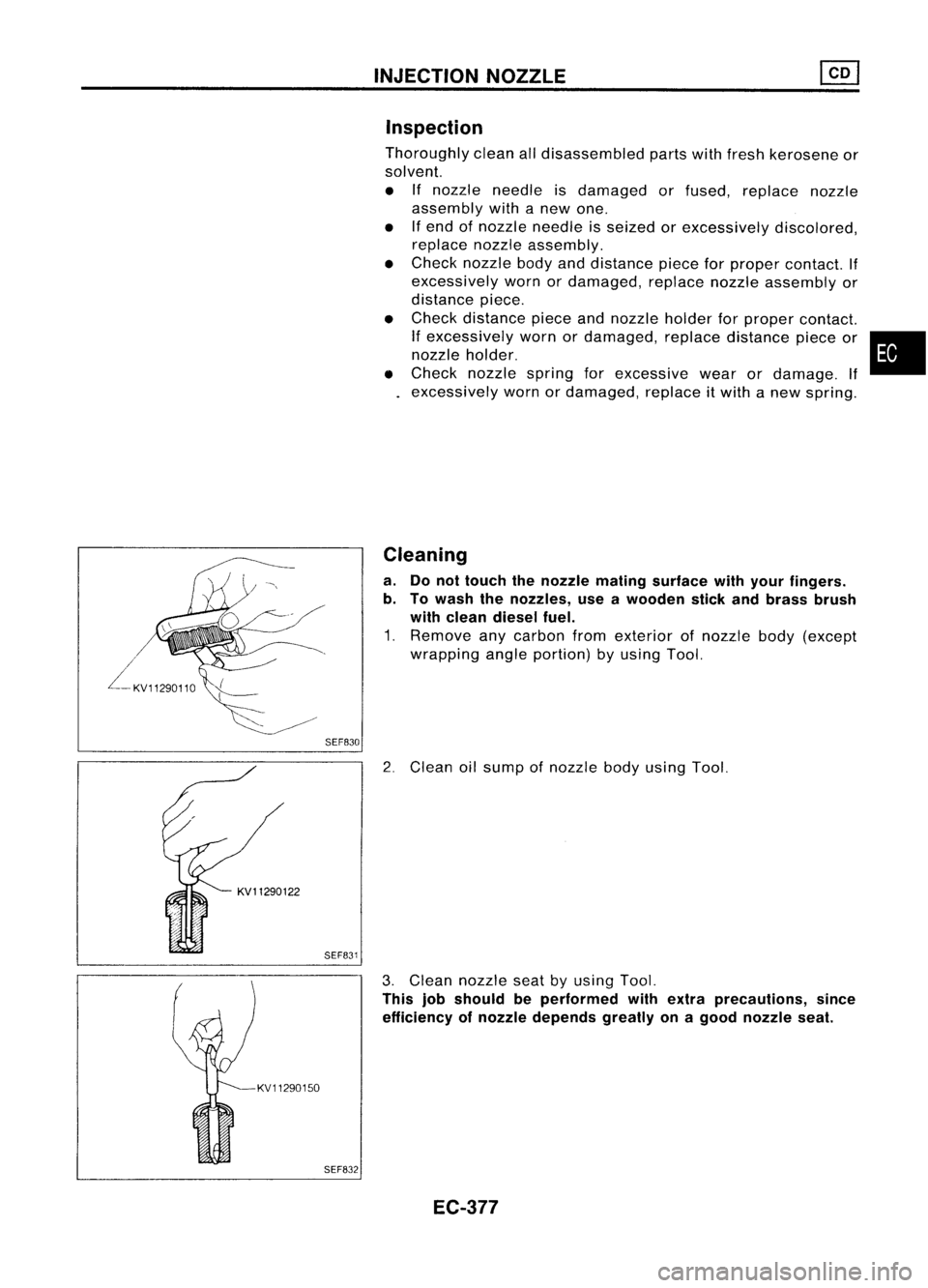
Inspection
Thoroughly cleanalldisassembled partswithfresh kerosene or
solvent.
• Ifnozzle needle isdamaged orfused, replace nozzle
assembly withanew one.
• Ifend ofnozzle needle isseized orexcessively discolored,
replace nozzleassembly.
• Check nozzle bodyanddistance pieceforproper contact. If
excessively wornordamaged, replacenozzleassembly or
distance piece.
• Check distance pieceandnozzle holderforproper contact.
If
excessively wornordamaged, replacedistance pieceor•
nozzle holder.
• Check nozzle springforexcessive wearordamage. If
excessively wornordamaged, replaceitwith anew spring.
Cleaning
a. Donot touch thenozzle mating surface withyour fingers.
b. Towash thenozzles, useawooden stickandbrass brush
with clean diesel fuel.
1. Remove anycarbon fromexterior ofnozzle body(except
wrapping angleportion) byusing Tool.
2. Clean oilsump ofnozzle bodyusing Tool.
KV11290150 SEF831
SEF832
3.
Clean nozzle seatbyusing Tool.
This jobshould beperformed withextra precautions, since
efficiency ofnozzle depends greatlyonagood nozzle seat.
EC-377
Page 1116 of 1701
TROUBLEDIAGNOSES ~
Quick-glow System(Cont'd)
• If
NG.
check component partsandtheir related harness
according tothe following chart.
Parts which should bechecked
Terminal Fuse Glowin-
No. Battery IFusible Glow
Key-in Ignition
dicatorHarness
link relay
switch switch
bulb
@
XX
X
@
X
X X X
@
XX
X X
@,@
XX XX
@
XX X
X X
@
X
X XX
COMPONENT INSPECTION
Glow relay
1. Check relayforcoil continuity.
Continuity shouldexist.
2. Check relayforproper operation.
Coil voltage Continuity
Contactpoint
OV
NoOFF
12V
Yes ON
•
Ohmmeter SEC5648
SEF630K Glow
plug
1. Remove glowplugconnecting plate.
2. Check eachglow plugforcontinuity.
Continuity shouldexist:
Approximately 0.650
• IfNG, replace glowplug.
EC-397
Page 1122 of 1701
If
NG, replace powersteering oilpressure switch.
Solenoid
timer
1. Disconnect solenoidtimerharness connector.
2. Apply battery voltage tosolenoid timerterminals andlisten
for operating sound.
•
No
Operating
sound
Yes
Condition
With battery voltage applied
Without batteryvoltage applied
TROUBLE
DIAGNOSES ~
Partial LoadAdvance (PLA)Control (Cont'd)
COMPONENT INSPECTION
Engine speedsensor
1. Disconnect enginespeedsensor harness connector.
2. Check resistance betweenterminals
@
and
CID.
Resistance: Approximately 1.6Q
If
NG, replace fuelpump.
EC-403