Page 1167 of 1701
•
less
than 0.18(0.0071)
0.12
-0.20 (0.0047 -0.0079)
0.05 -0.09 (0.0020 -0.0035)
0.05 -0.11 (0.0020 -0.0043)
0.05 -0.09 (0.0020 -0.0035)
Body
toouter gearclearance
CD
Outer geartoinner gearclearance
@
Housing toinner gearclearance @
Housing toouter gearclearance
@
Inner geartohousing clearance @
If
itexceeds thelimit, replace gearsetorentire oilpump
assembly.
SLC560A
ENGINE
LUBRICATION SYSTEM
Oil Pump (Cont'd)
INSPECTION
Using afeeler gauge, checkthefollowing clearances.
Unit:mm(in)
SLC561C
SLC568A REGULATOR VALVEINSPECTION
1. Visually inspectcomponents forwear anddamage.
2. Check oilpressure regulator valvesliding surface andvalve
spring.
3. Coat regulator valvewithengine oil.Check that
it
falls freely
into thevalve holebyitsown weight.
If
damaged, replaceregulator valvesetoroil pump assembly.
SLC049B LC-29
Page 1168 of 1701
ENGINELUBRICATION SYSTEM
Oil Pump (Cont'd)
OIL PRESSURE RELIEFVALVEINSPECTION
Inspect oilpressure reliefvalve (indicated byarrow) for
movement, cracksandbreaks bypushing theball. Ifreplace-
ment isnecessary, removevalvebyprying itout with asuitable
tool. Install anew valve inplace bytapping it.
SLC446 OilCooler
SEC. 150-213
RHO
tOJ
16-21
(1.6. 2.1,12•15)
/
tOJ
34-44
11 ~
f:1
(3.5 -4.5, 25-33)
Front ~ LHO
:N.m (kg-m, ft-Ib)
Front
~
SLC047B
CD
Oilcooler
@
Connector
@
a-ring
@
Oilfilter bracket
@
Gasket
@
Cover
INSPECTION
1. Check oilcooler element andhousing forcracks.
2. Check coolant inletofoil cooler forclogging byblowing
through it.
Replace itifnecessary.
Oil cooler
SLC465A LC-30
Page 1178 of 1701

Oilpressure checkSERVICE
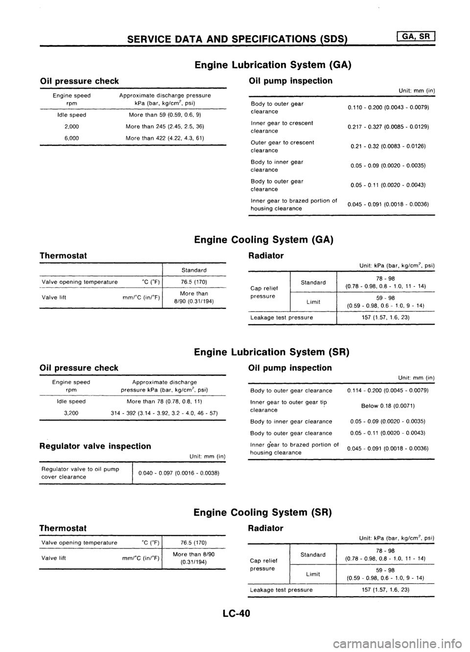
DATAANDSPECIFICATIONS (50S)
Engine Lubrication System(GA)
Oil pump inspection
I
GA, SR
I
Engine speed
rpm
Idle speed
2,000
6,000
Approximate
dischargepressure
kPa (bar, kg/cm?, psi)
More than
59(0.59, 0.6,9)
More than
245(2.45, 2.5,36)
More than
422(4,22, 4.3,61)
Body
toouter gear
clearance
Inner geartocrescent
clearance
Outer geartocrescent
clearance
Body toinner gear
clearance
Body toouter gear
clearance
Inner geartobrazed portionof
housing clearance Unit:
mm(in)
0.110 -0.200 (0.0043 -0.0079)
0.217 -0.327 (0.0085 -0.0129)
0.21 -0.32 (0.0083 -0.0126)
0.05 -0.09 (0.0020 -0.0035)
0.05 -0 11 (0.0020 -0.0043)
0.045 -0.091 (0.0018 -0.0036)
Thermostat Engine
Cooling System(GA)
Radiator
Standard Unit:
kPa(bar, kg/cm?, psi)
Valve opening temperature °C("F)
Valve lift mml'C(inI'F)
76.5
(170)
More than
8/90 (0.31/194)
Standard
Cap relief
pressure Limit
Leakage testpressure
78
-98
(0.78 -0.98, 0.8-10, 11-14)
59 -98
(059 -0.98, 06-10, 9-14)
157 (1.57, 16,23)
Oil pressure check Engine
Lubrication System(SR)
Oil pump inspection
Engine speed
rpm
Idle speed
3,200
Approximate
discharge
pressure kPa(bar,
kg/cm?,
psi)
More than
78(0.78, 0.8,11)
314 -392 (3.14 -3.92, 3.2-4.0, 46-57)
Body
toouter gearclearance
Inner geartoouter geartip
clearance . Unit:
mm(in)
0,114 -0,200 (0.0045 -0.0079)
Below
0.18(0.0071)
Regulator valveinspection
Unit:mm(in) Body
toinner gearclearance
Body toouter gearclearance
Inner g-eartobrazed portionof
housing clearance
0.05
-0.09 (0.0020 -0.0035)
0.05 -0.11 (0.0020 -0,0043)
0.045 -0,091 (0,0018 -0,0036)
Regulator valvetooil pump
cover clearance
Thermostat 0040
-0097 (0,0016 -0.0038)
Engine Cooling System(SR)
Radiator
Valve opening temperature
Valve lift
°C
(OF)
mml"C
(inI"F)
765
(170)
More than
8/90
(0,31/194)
Standard
Cap relief
pressure Limit
Leakage testpressure
LC-40
Unit:
kPa(bar, kg/em?, psi)
78 -98
(0.78 -0,98, 0.8-1,0, 11-14)
59 -98
(0,59 -0.98, 0.6-1.0, 9-14)
157 (1.57, 1.6,23)
Page 1179 of 1701
SERVICEOATAAND SPECIFICATIONS (SOS)
Oil pressure check Engine
Lubrication System
Oil pump inspection
Unit:mm(in)
Body toouter gearclearance 0.12-0.20 (0.0047 -0.0079)
Outer geartoinner gearclearance Lessthan0.18(0.0071)
Engine
rpm
Idle speed
2,000 Approximate
dischargepressure
kPa (bar, kg/cm
2,
psi)
More than59(0.59, 0.6,9)
294 (2.9, 3,43) Housing
toinner gearclearance
Housing toouter gearclearance
Inner geartohousing clearance 0.05
-0.09 (0.0020 -0.0035)
0.05 -0.11 (0.0020 -0.0043)
0.05 -0.09 (0.0020 -0.0035)
•
Thermostat Engine
Cooling System
Radiator
Unit:kPa(bar, kg/cm
2,
psi)
Leakage testpressure
Valve
opening temperature
°c
(OF)
Valve lift
mmrC
(inrF)
88
(190)
More than10/100 (0.39/212) Cap
relief
pressure
LC-41
Standard
Limit 78
-98 (0.78 -0.98, 0.8-1.0,11 -14)
59 -98 (0.59 -0.98, 06-1.0, 9-14)
157 (1.57,1.6,23)
Page 1180 of 1701

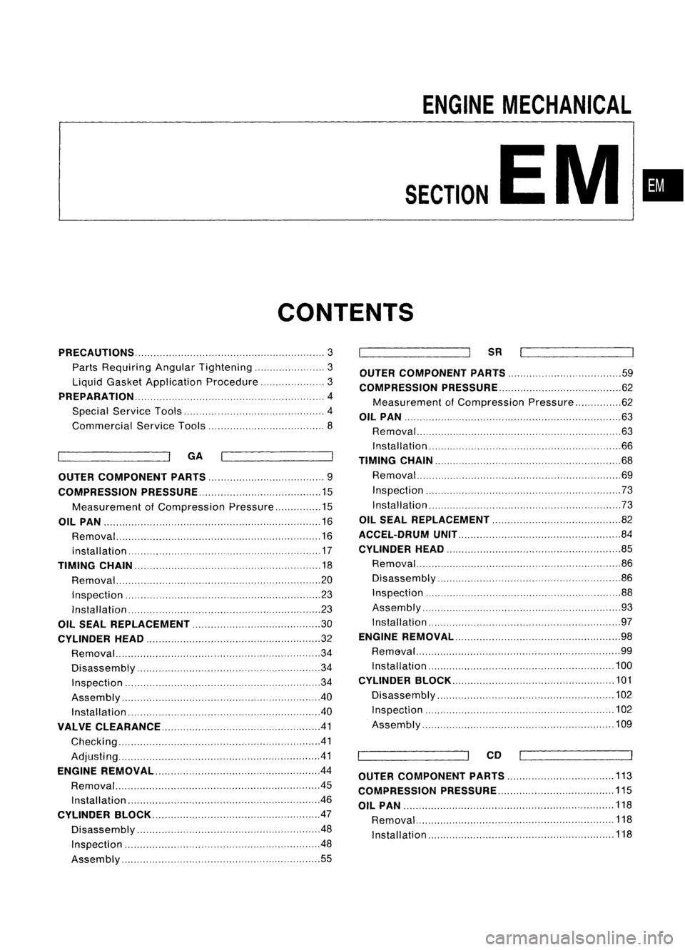
ENGINEMECHANICAL
SECTION
EM
CONTENTS
•
PRECAUTIONS
3
Parts Requiring AngularTightening 3
Liquid Gasket Application Procedure 3
PREPARATION 4
Special Service Tools 4
Commercial ServiceTools 8
GA
OUTER COMPONENT PARTS 9
COMPRESSION PRESSURE 15
Measurement ofCompression Pressure 15
OIL PAN 16
Removal 16
installation 17
TIMING CHAIN
18
Removal. 20
Inspection 23
Installation 23
OIL SEAL REPLACEMENT 30
CYLINDER HEAD 32
Removal 34
Disassembly 34
Inspection 34
Assembly 40
Installation 40
VALVE CLEARANCE 41
Checking 41
Adjusti ng 41
ENGINE REMOVAL .44
Removal 45
Ins taIIat ion " 46
CYLINDER BLOCK 47
Disassembly 48
Inspection 48
Assembly 55
SR
OUTER COMPONENT PARTS 59
COMPRESSION PRESSURE 62
Measurement ofCompression Pressure 62
OIL PAN
63
Removal 63
Installation ,66
TIMING CHAIN 68
Removal 69
Inspection 73
Installation ,73
OIL SEAL REPLACEMENT 82
ACCEL-DRUM UNIT 84
CYLINDER HEAD
85
Removal 86
Disassembly 86
Inspection 88
Assembly 93
Installation , 97
ENGINE REMOVAL 98
RemGval 99
Installation "100
CYLINDER BLOCK 101
Disassembly 102
Inspection , 102
Assembly 109
CD
OUTER COMPONENT PARTS
113
COMPRESSION PRESSURE 115
OIL PAN 118
Removal 118
Installation 118
Page 1194 of 1701

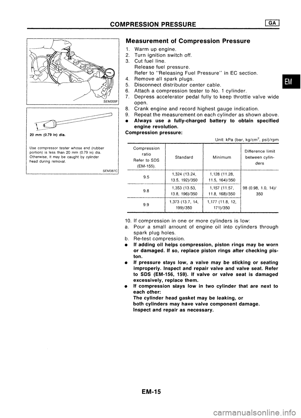
COMPRESSIONPRESSURE
20
mm
(O.79 In)dls.
Use compressor testerwhose end(rubber
portion) isless than 20mm (0.79 in)dia.
Otherwise, itmay becaught bycylinder
head during removal.
SEM387CMeasurement
ofCompression Pressure
1. Warm upengine.
2. Turn ignition switchoff.
3. Cut fuel line.
Release fuelpressure.
Refer to"Releasing FuelPressure" inEC section. •
4. Remove allspark plugs.
5. Disconnect distributorcentercable.
6. Attach acompression testertoNO.1 cylinder.
7. Depress accelerator pedalfullytokeep throttle valvewide
open.
8. Crank engine andrecord highest gaugeindication.
9. Repeat themeasurement oneach cylinder asshown above.
• Always useafully-charged batterytoobtain specified
engine revolution.
Compression pressure:
Unit:kPa(bar, kg/cm
2,
psi)/rpm
Compression Differencelimit
ratio
Standard
Refer toSOS Minimum
betweencylin-
(EM-155). ders
9.5 1,324
(13.24, 1,128(11.28,
13.5, 192)/350 11.5,164)/350
9.8 1,353
(1353, 1,157(11.57, 98(0.98, 1.0,14)/
13.8, 196)/350 11.8,168)/350
350
9.9 1,373
(13.7, 14, 1,177(11.8,12,
199)/350 171)/350
10.
If
compression inone ormore cylinders islow:
a. Pour asmall amount ofengine oilinto cylinders through
spark plugholes.
b. Re-test compression,
• Ifadding oilhelps compression, pistonringsmaybeworn
or damaged. Ifso, replace pistonringsafterchecking pis-
ton.
• Ifpressure stayslow,avalve maybesticking orseating
improperly. Inspectandrepair valveandvalve seat.Refer
to SOS (EM-156, 159).Ifvalve orvalve seatisdamaged
excessively, replacethem.
• Ifcompression stayslowintwo cylinder thatarenext to
each other:
The cylinder headgasket maybeleaking, or
both cylinders mayhave valve component damage.
Inspect andrepair asnecessary.
EM-15
Page 1202 of 1701
TIMINGCHAIN
Inspection
Check forcracks andexcessive wearatroller links.Replace if
necessary.
•
SEM1190
No. 1cylinder atTDC
Installation
1. Position crankshaft sothat No.1piston isat TOC andkey
way isat 12 o'clock.
a. Install crankshaft sprocket.
• Make suremating marksoncrankshaft sprocketfacefront
of engine.
b. Install oilpump drivespacer.
SEM377CC
--40
rollers
2.
Install chainguide.
3. Install crankshaft sprocketandlower timing chain.
• Settiming chainbyaligning itsmating markwiththeone on
crankshaft sprocket.
• Make suresprocket's matingmarkfaces engine front.
• The number oflinks between alignment marksare thesame
for the leftand ri.Qht sides. Eithersidecanbeused during
alignment withthesprocket.
SEM127F
/
Same number link
///
40 rollers-
• :Mating mark(different color)
EM-23
Page 1203 of 1701

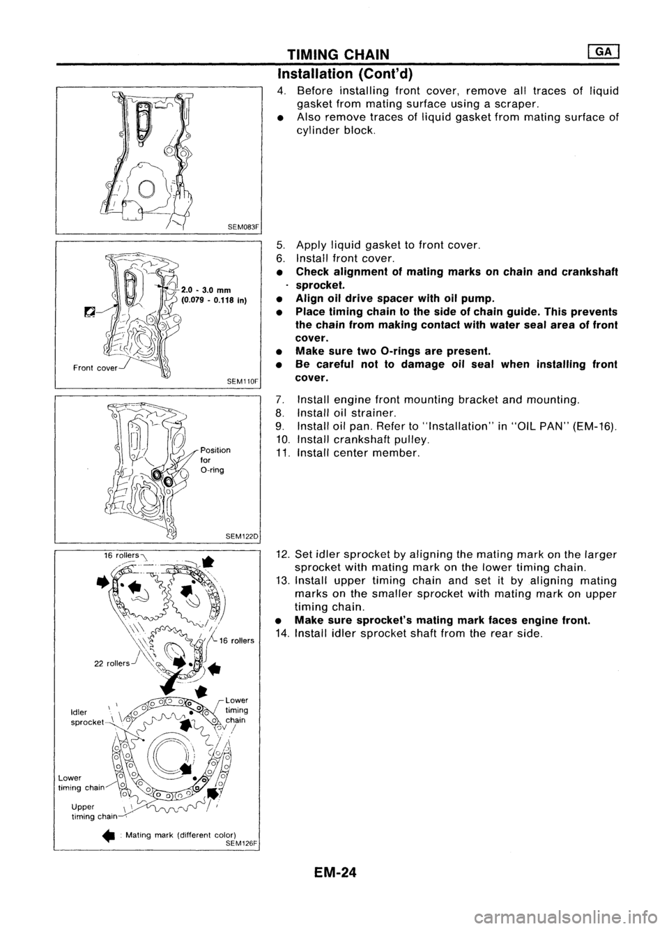
TIMINGCHAIN ~
Installation (Cont'd)
4. Before installing frontcover, remove alltraces ofliquid
gasket frommating surface usingascraper.
• Also remove tracesofliquid gasket frommating surface of
cylinder block.
5. Apply liquidgasket tofront cover.
6. Install frontcover.
• Check alignment ofmating marksonchain andcrankshaft
sprocket.
• Align oildrive spacer withoilpump.
• Place timing chaintothe side ofchain guide. Thisprevents
the chain frommaking contact withwater sealarea offront
cover.
• Make suretwoO-rings arepresent.
• Be careful nottodamage oilseal when installing front
cover.
7. Install engine frontmounting bracketandmounting.
8. Install oilstrainer.
9. Install oilpan. Refer to"Installation" in"OIL PAN" (EM-16).
10. Install crankshaft pulley.
11. Install center member.
12. Set idler sprocket byaligning themating markonthe larger
sprocket withmating markonthe lower timing chain.
13. Install uppertiming chainandsetitby aligning mating
marks onthe smaller sprocket withmating markonupper
timing chain.
• Make suresprocket's matingmarkfaces engine front.
14. Install idlersprocket shaftfromtherear side.
SEM083F
SEM110F
SEM122D
Position
for
O-ring
Front
cover
Upper timing chain
•. Mating mark(different color)
SEM126F
Idler
sprocket
Lower
timing chain
EM-24