1995 NISSAN ALMERA N15 check oil
[x] Cancel search: check oilPage 1318 of 1701
![NISSAN ALMERA N15 1995 Service Manual
SEM530D
CYLINDER
HEAD
[£[]
Installation (Cont'd)
Relation between pistonaverage projection andcylinder head
gasket (ChartA)
Average valueof
Gasketthickness Grade
piston projec-
mm(in) (Number NISSAN ALMERA N15 1995 Service Manual
SEM530D
CYLINDER
HEAD
[£[]
Installation (Cont'd)
Relation between pistonaverage projection andcylinder head
gasket (ChartA)
Average valueof
Gasketthickness Grade
piston projec-
mm(in) (Number](/manual-img/5/57349/w960_57349-1317.png)
SEM530D
CYLINDER
HEAD
[£[]
Installation (Cont'd)
Relation between pistonaverage projection andcylinder head
gasket (ChartA)
Average valueof
Gasketthickness Grade
piston projec-
mm(in) (Number
of
tions notches)
mm (in)
Newparts
Inassembly
1.25 (0.0492) 1.1~gg~
0
Less than
0.505 (0.0433
~ggg;~)
(0.0199) 1.15_+gg~
1.30 (0.0512)
(0.0453~ggg~g) 1
0.505 -0.555
1.35(0.0931) 1.20_+gg~
(0.0199 -0.0219)
(0.0472~ggg~g ) 2
.
Over
0.555 1.25_+gg~
(0.0219) 1.40
(0.0551)
(0.0492~ggg~g ) 3
Step 6
Check ifthe average valueofeach projection obtainedfrom
step 2is larger thanthemax. value ofthe standard projection
(of selected gasket)incremented by0.05 mm(0.0020 in).
If so, use gasket thatis1grade thicker. Ifnot so,use gasket as
selected instep 4.
•
Example
Unit:mm(in)
Step Cylinder
No.
1 2 34
Item
M1M2M3 M4M1 M2M3 M4M1
M2M3
.
M4 M1
M2M3M4
1. Measured
value 0.53
0.560.53 0.560.59 0.55 0.59
0550.53 0.580.57
0.54
0.58 0.51052 0.57
(0.0209) (0.0220)(0.0209)(0.0220)
(0.0232)(0.0217)
(0.0232)(0.0217)(0.0209)(0.0228)(0.0224)(0.0213)(0.0228) (0.0201)(0.0205) (0.0224)
Average 0.545 0.57
0.555 0.545
2 value
ofeach
(0.0215) (0.0224)-(0.0219)
(0.0215)
piston
Average
3 value
ofall 055375(0.02180)
pistons
4. Round
off
0.554(0.0218)'1
value
Determined
5. gasket
thick-
120(0.0472) (Grade8)
ness (Tempo-
rarily)
X: Maximum valueofstandard projection ofselected gasket...0.555 (0.0219) (inchart A)
+
0.05 (0.0020)
=
0.605 (0.0238)
6. Y:Maximum valueinstep 2
=
0.57 (0.0224)
The relationship betweenXand Yis "X
>
Y.... 2
Determined
7. gasket thick- 1.20(0.0472) (Grade8)'2
ness (Finally)
*1: IIthe average value
01
projections lorallpistons is,lor example, 0.553(7)5,as shown inthe table above, itshould berounded oilasfol-
lows:
II the digit inthe forth decimal place(which isenclosed byacircle inthis case) issmaller than5,the average valueshould beregarded
as 0.553 mm(0.0218 in);ilitis larger than5,the average valueshould beregarded as0.554 mm(0.0218 in).
*2: IIX
<
Y, then thethicker gradeCgasket mustbeused.
EM-139
Page 1325 of 1701
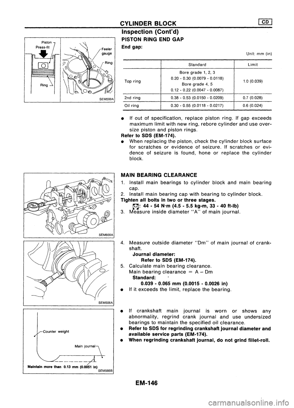
Feelergauge
SEM599A
SEM506A
Main jOUrnal~
Maintain morethan0.13mm(0.0051 In)
SEM566B CYLINDER
BLOCK
Inspection (Cont'd)
PISTON RINGENDGAP
End gap:
Unit:mm(in)
Standard Limit
Bore grade 1,2, 3
Top ring 0.20
-0.30 (0.0079 -0.0118)
1.0(0.039)
Bore grade 4,5
0.12 -0.22 (0.0047 -0.0087)
2nd ring 0.38-0.53 (0.0150 -0.0209) 0.7(0.028)
Oil ring 0.30
-0.55 (0.0118 -0.0217) 0.6(0.024)
• Ifout ofspecification, replacepistonring.Ifgap exceeds
maximum limitwithnewring, rebore cylinder anduseover-
size piston andpiston rings.
Refer toSOS (EM-174).
• When replacing thepiston, checkthecylinder blocksurface
for scratches orevidence ofseizure. Ifscratches orevi-
dence ofseizure isfound, honeorreplace thecylinder
block.
MAIN BEARING CLEARANCE
1. Install mainbearings tocylinder blockandmain bearing
cap.
2. Install mainbearing capwith bearing tocylinder block.
Tighten allbolts intwo orthree stages.
~: 44-54 N'm (4.5-5.5 kg-m, 33-40 ft-Ib)
3. Measure insidediameter" A"ofmain journal.
4. Measure outsidediameter "Om"ofmain journal ofcrank-
shaft.
Journal diameter:
Refer toSOS (EM-174).
5. Calculate mainbearing clearance.
Main bearing clearance
=
A-Om
Standard:
0.039 -0.065 mm(0.0015 -0.0026 in)
• Ifitexceeds thelimit, replace thebearing.
• Ifcrankshaft mainjournal isworn orshows any
abnormality, regrindcrankjournal anduseundersized
bearings tomaintain thespecified oilclearance.
• Refer toSOS forregrinding crankshaftjournaldiameter and
available serviceparts(EM-174).
• When regrinding crankshaftjournal,donot grind fillet-roll.
EM-146
Page 1328 of 1701
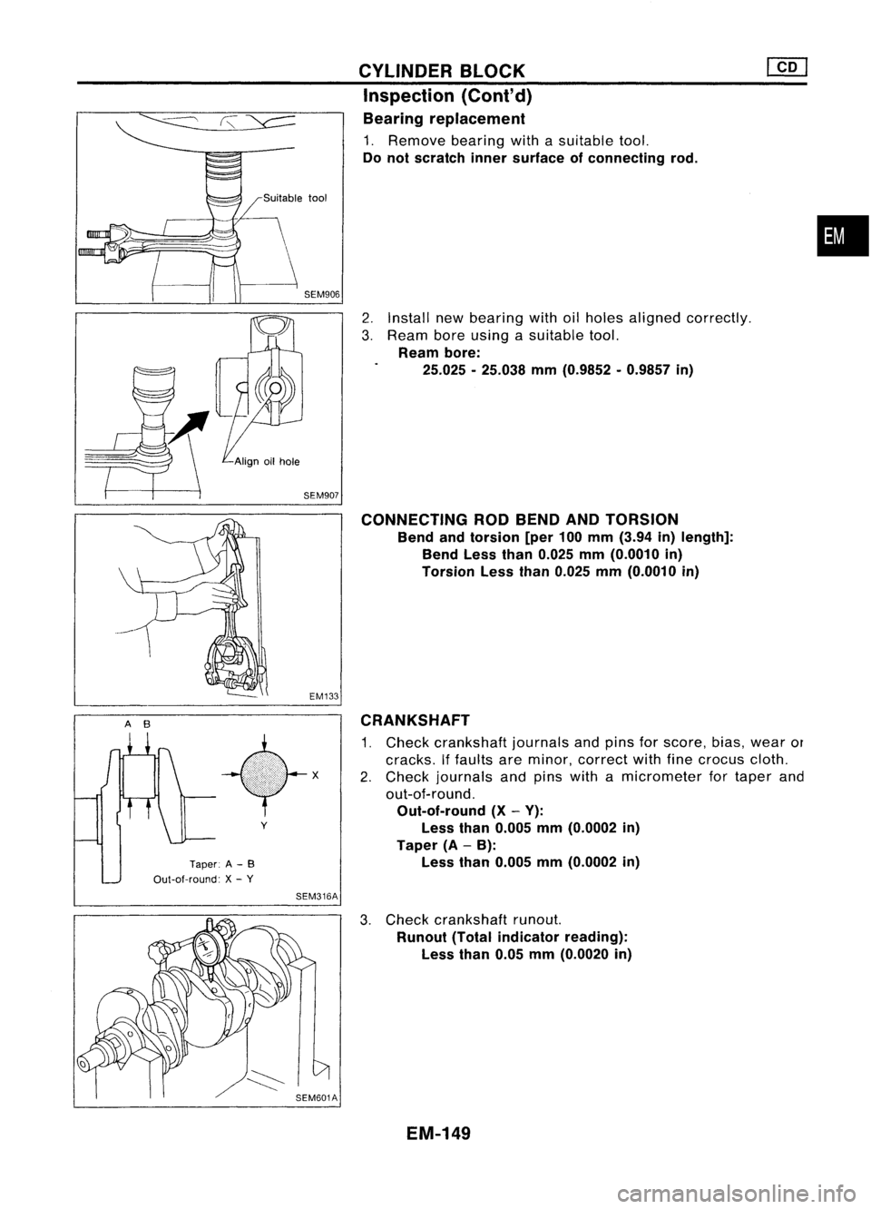
AB
Taper:A-B
Out-ot-round: X-y
y
SEM316A CYLINDER
BLOCK
Inspection (Cont'd)
Bearing replacement
1. Remove bearingwithasuitable tool.
Do not scratch innersurface ofconnecting rod.
2. Install newbearing withoilholes aligned correctly.
3. Ream boreusing asuitable tool.
Ream bore:
25.025 -25.038 mm(0.9852 -0.9857 in)
CONNECTING RODBEND ANDTORSION
Bend andtorsion [per100mm (3.94 in)length]:
Bend Lessthan0.025 mm(0.0010 in)
Torsion Lessthan0.025 mm(0.0010 in)
CRANKSHAFT
1. Check crankshaft journalsandpins forscore, bias,wear or
cracks. Iffaults areminor, correct withfinecrocus cloth.
2. Check journals andpins withamicrometer fortaper and
out-of-round.
Out-of-round (X-V):
Less than0.005 mm(0.0002 in)
Taper (A-B):
Less than0.005 mm(0.0002 in)
•
3. Check crankshaft runout.
Runout (Totalindicator reading):
Less than0.05mm(0.0020 in)
EM-149
Page 1355 of 1701
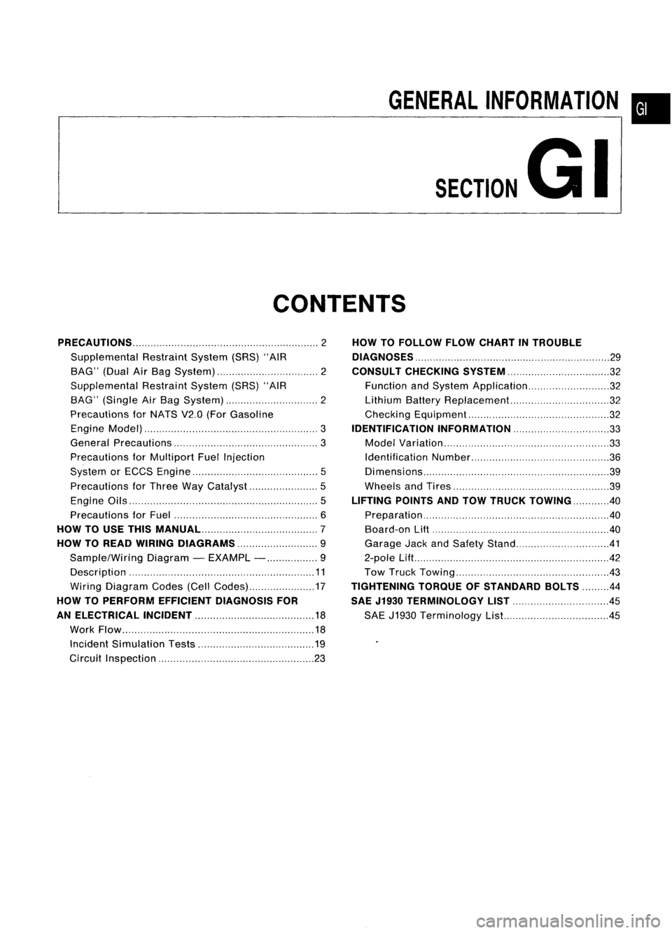
GENERALINFORMATION •
SECTION
G
I
CONTENTS
PRECAUTIONS 2
Supplemental RestraintSystem(SRS)"AIR
BAG" (DualAirBag System) 2
Supplemental RestraintSystem(SRS)"AIR
BAG" (Single AirBag System) 2
Precautions forNATS V2.0(ForGasoline
Engine Model) 3
General Precautions 3
Precautions forMultiport FuelInjection
System orECCS Engine 5
Precautions forThree WayCatalyst 5
Engine Oils 5
Precautions forFuel 6
HOW TOUSE THIS
MANUAL 7
HOW TOREAD WIRING DIAGRAMS 9
Sample/Wiring Diagram-EXAMPL - 9
Description 11
Wiring Diagram Codes(CellCodes) 17
HOW TOPERFORM EFFICIENT DIAGNOSIS FOR
AN ELECTRICAL INCIDENT 18
Work Flow 18
Incident Simulation Tests 19
Circuit Inspection 23
HOW
TOFOLLOW FLOWCHART INTROUBLE
DIAGNOSES 29
CONSULT CHECKING SYSTEM
32
Function andSystem Application 32
Lithium BatteryReplacement.. 32
Checking Equipment 32
IDENTIFICATION INFORMATION 33
Model Variation 33
Identification Number 36
Di mens ions 39
Wheels andTires 39
LIFTING POINTSANDTOW TRUCK TOWING ..40
Preparation 40
Board-on
Lift
40
Garage JackandSafety Stand 41
2-pole Lift 42
Tow Truck Towing 43
TIGHTENING TORQUEOFSTANDARD BOLTS
44
SAE J1930 TERMINOLOGY LIST 45
SAE J1930 Terminology List.. 45
Page 1359 of 1701
PRECAUTIONS
General Precautions (Cont'd)
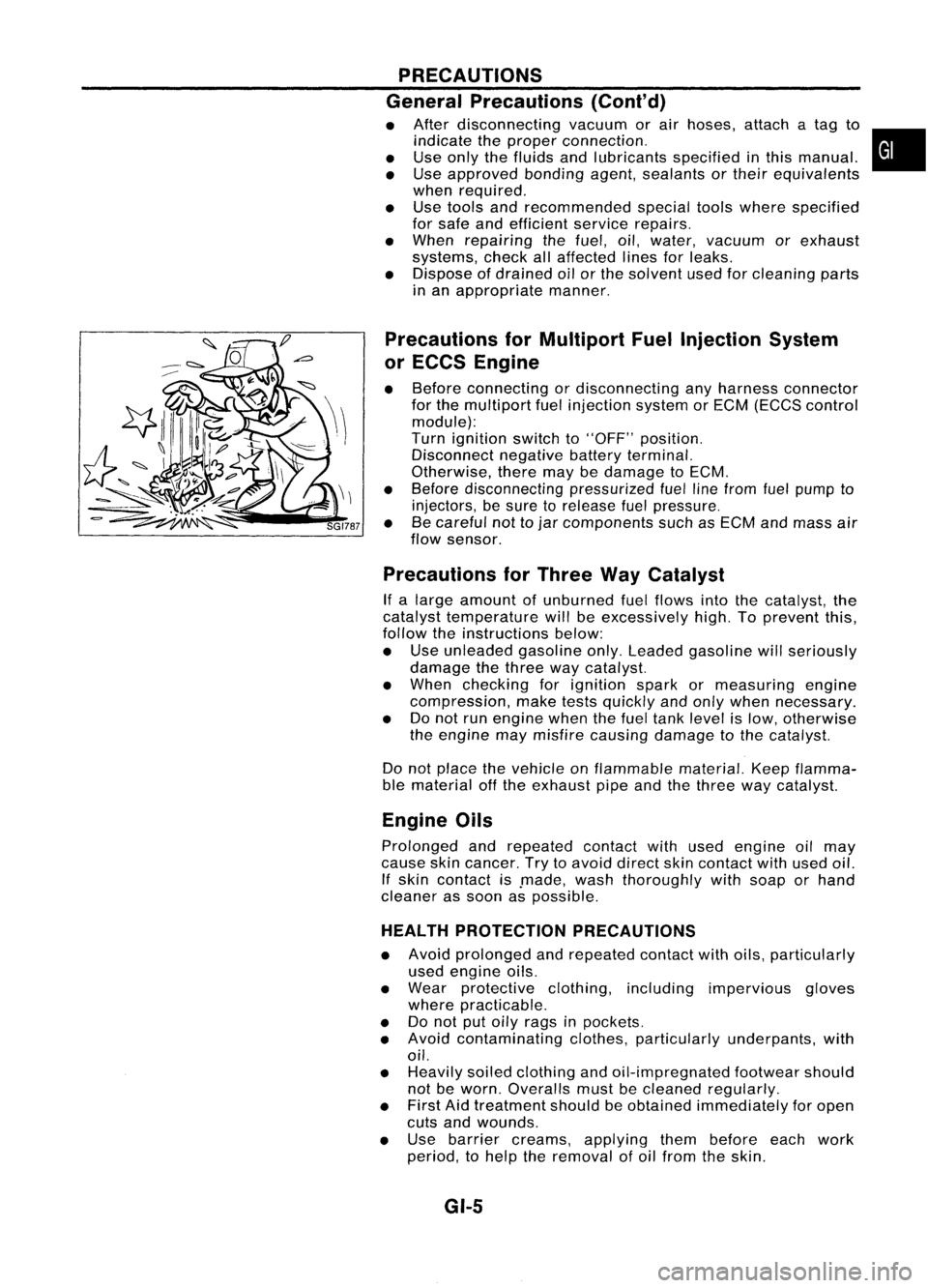
• After disconnecting vacuumorair hoses, attachatag to
indicate theproper connection.
• Use only thefluids andlubricants specifiedinthis manual.
• Use approved bondingagent,sealants ortheir equivalents
when required.
• Use tools andrecommended specialtoolswhere specified
for safe andefficient servicerepairs.
• When repairing thefuel, oil,water, vacuum orexhaust
systems, checkallaffected linesforleaks.
• Dispose ofdrained oilorthe solvent usedforcleaning parts
in an appropriate manner.
Precautions forMultiport FuelInjection System
or ECCS Engine
• Before connecting ordisconnecting anyharness connector
for the multiport fuelinjection systemorEGM (EGGS control
module):
Turn ignition switchto"OFF" position.
Disconnect negativebatteryterminal.
Otherwise, theremaybedamage toEGM.
• Before disconnecting pressurizedfuellinefrom fuelpump to
injectors, besure torelease fuelpressure.
• Becareful nottojar components suchasEGM andmass air
flow sensor.
Precautions forThree WayCatalyst
If a large amount ofunburned fuelflows intothecatalyst, the
catalyst temperature willbeexcessively high.Toprevent this,
follow theinstructions below:
• Use unleaded gasolineonly.Leaded gasoline willseriously
damage thethree waycatalyst.
• When checking forignition sparkormeasuring engine
compression, maketestsquickly andonly when necessary.
• Donot run engine whenthefuel tank level islow, otherwise
the engine maymisfire causing damage tothe catalyst.
Do not place thevehicle onflammable material.Keepflamma-
ble material offthe exhaust pipeandthethree waycatalyst.
Engine Oils
Prolonged andrepeated contactwithused engine oilmay
cause skincancer. Trytoavoid direct skincontact withused oil.
If skin contact is.made, washthoroughly withsoap orhand
cleaner assoon aspossible.
HEALTH PROTECTION PRECAUTIONS
• Avoid prolonged andrepeated contactwithoils, particularly
used engine oils.
• Wear protective clothing,including impervious gloves
where practicable.
• Donot putoily rags inpockets.
• Avoid contaminating clothes,particularly underpants, with
oil.
• Heavily soiledclothing andoil-impregnated footwearshould
not beworn. Overalls mustbecleaned regularly.
• First Aidtreatment shouldbeobtained immediately foropen
cuts andwounds.
• Use barrier creams, applying thembefore eachwork
period, tohelp theremoval ofoil from theskin.
GI-5
•
Page 1360 of 1701
PRECAUTIONS
Engine Oils(ConI' d)
• Wash withsoap andwater toensure alloil isremoved (skin
cleansers andnailbrushes willhelp). Preparations contain-
ing lanolin replace thenatural skinoilswhich havebeen
removed.
• Donot use gasoline, kerosine, dieselfuel,gasoil,thinners
or solvents forcleaning skin.
• If
skin disorders develop,obtainmedical advicewithout
delay.
• Where practicable, degreasecomponents priortohandling.
• Where thereisarisk ofeye contact, eyeprotection should
be worn, forexample, chemicalgogglesorface shields; in
addition aneye wash facility should beprovided.
ENVIRONMENTAL PROTECTIONPRECAUTIONS
Burning usedengine oilinsmall space heaters orboilers can
be recommended onlyforunits ofapproved design.Theheat-
ing system mustmeettherequirements ofHM Inspectorate of
Pollution forsmall burners ofless than 0.4MW. Ifin doubt check
with theappropriate localauthority and/ormanufacturer ofthe
approved appliance.
Dispose ofused oiland used oilfilters through authorized
waste disposal contractors tolicensed wastedisposal sites,or
to the waste oilreclamation trade.Ifin doubt, contact thelocal
authority foradvice ondisposal facilities.
It is illegal topour used oilontothe ground, downsewers or
drains, orinto water courses.
The regulations concerningthepollution ofthe environment
will vary between regions.
Precautions forFuel
GASOLINE ENGINE:
For Europe
Unleaded gasolineofat least 95octane (RON)
CAUTION: Do not use leaded gasoline. Usingleaded gasoline willdamage
the catalytic converter.
Except Europe
Unleaded gasolineofat least 91octane (RON)
DIESEL ENGINE*:
Diesel fuelofat least 50cetane
If two types ofdiesel fuelareavailable, usesummer or
winter fuelproperly according tothe following temperature
conditions.
• Above -rc(20°F) Summer typediesel fuel.
• Below
-rc
(20°F) Wintertypediesel fuel.
CAUTION:
• Donot use home heating oil,gasoline, orother alternate
fuels inyour diesel engine. Theuseofthose cancause
engine damage.
• Donot use summer fuelattemperature below_7°C(20°F).
The cold temperatures willcause waxtoform inthe fuel. As
a result, itmay prevent theengine fromrunning smoothly.
• Donot add gasoline orother alternate fuelstodiesel fuel.
GI-6
Page 1362 of 1701
HOWTOUSE THIS MANUAL
ManualTransaxle/Transmission
Automatic Transaxle/
Transmission
Air Conditioner
Power Steering
Special Service Tools
Society ofAutomotive Engineers,
Inc.
Automatic Transmission Fluid
Drive range 1stgear
Drive range 2ndgear
Drive range 3rdgear
Drive range 4thgear
Overdrive
2nd range 2ndgear
2nd range 1stgear
1st range 2ndgear
1st range 1stgear
A/C
PIS
Tool SAE
ATF
0
1
O
2
0
3
0
4
00
2
2
2
1
1
2
1
1
•
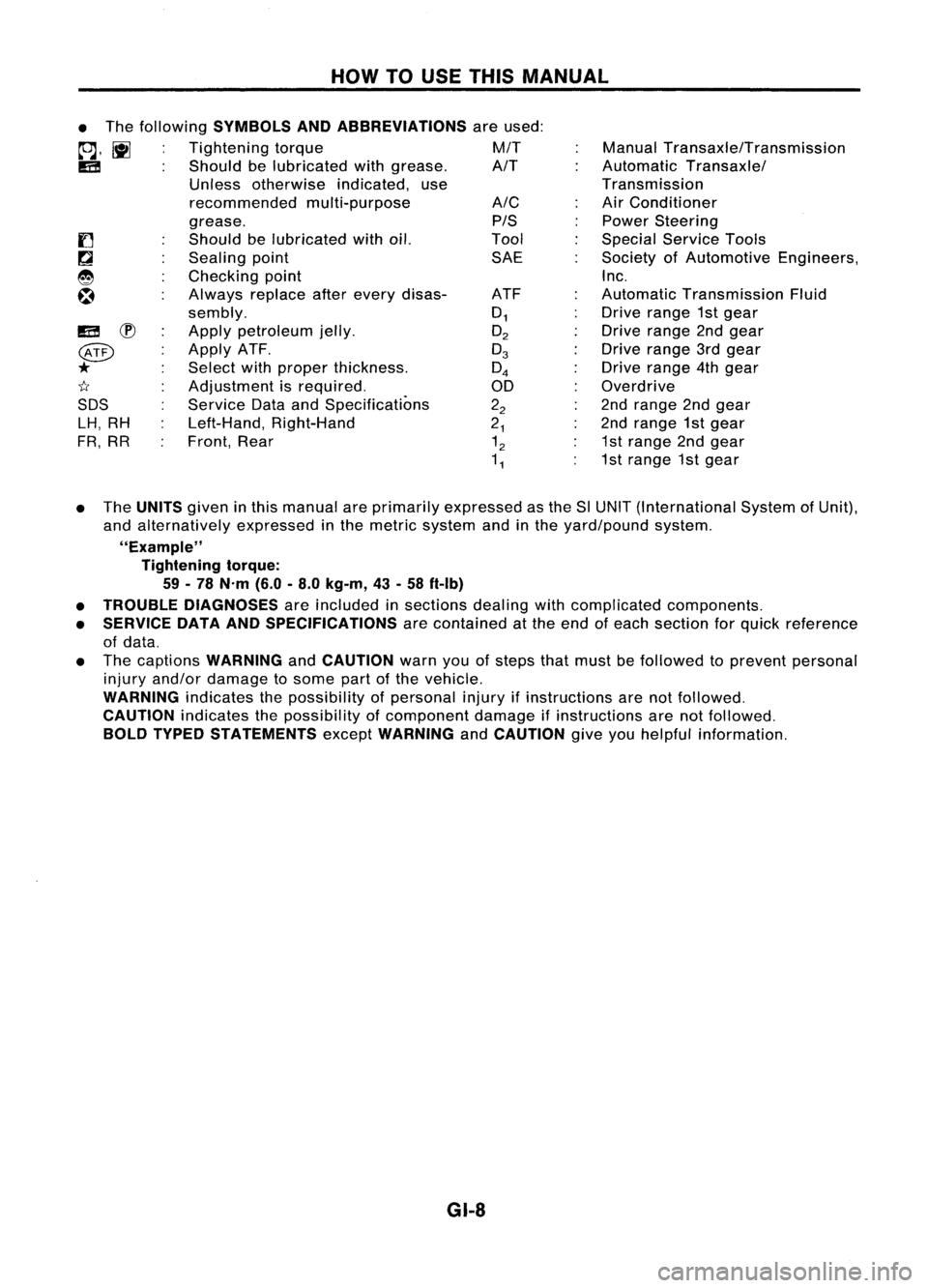
The following
SYMBOLS ANDABBREVIATIONS
areused:
to;J,
l\tI
Tightening torque M/T
IE!
Shouldbelubricated withgrease. A/T
Unless otherwise indicated,use
recommended multi-purpose
grease.
Should belubricated withoil.
Sealing point
Checking point
Always replaceafterevery disas-
sembly.
Apply petroleum jelly.
Apply ATF.
Select withproper thickness.
Adjustment isrequired.
Service DataandSpecifications
Left-Hand, Right-Hand
Front, Rear
IE!
~
@
*
1I
SDS LH, RH
FR, RR
• The
UNITS
giveninthis manual areprimarily expressed asthe SlUNIT (International SystemofUnit),
and alternatively expressedinthe metric system andinthe yard/pound system.
"Example" Tightening torque:
59 -78 N'm (6.0-8.0 kg-m, 43-58 ft-Ib)
• TROUBLE DIAGNOSES
areincluded insections dealingwithcomplicated components.
• SERVICE DATAANDSPECIFICATIONS
arecontained atthe end ofeach section forquick reference
of data.
• The captions
WARNING
and
CAUTION
warnyouofsteps thatmust befollowed toprevent personal
injury and/or damage tosome partofthe vehicle.
WARNING
indicatesthepossibility ofpersonal injuryifinstructions arenotfollowed.
CAUTION
indicatesthepossibility ofcomponent damageifinstructions arenotfollowed.
BOLD TYPED STATEMENTS
except
WARNING
and
CAUTION
giveyouhelpful information.
GI-8
Page 1412 of 1701
DESCRIPTION
Refrigeration Cycle
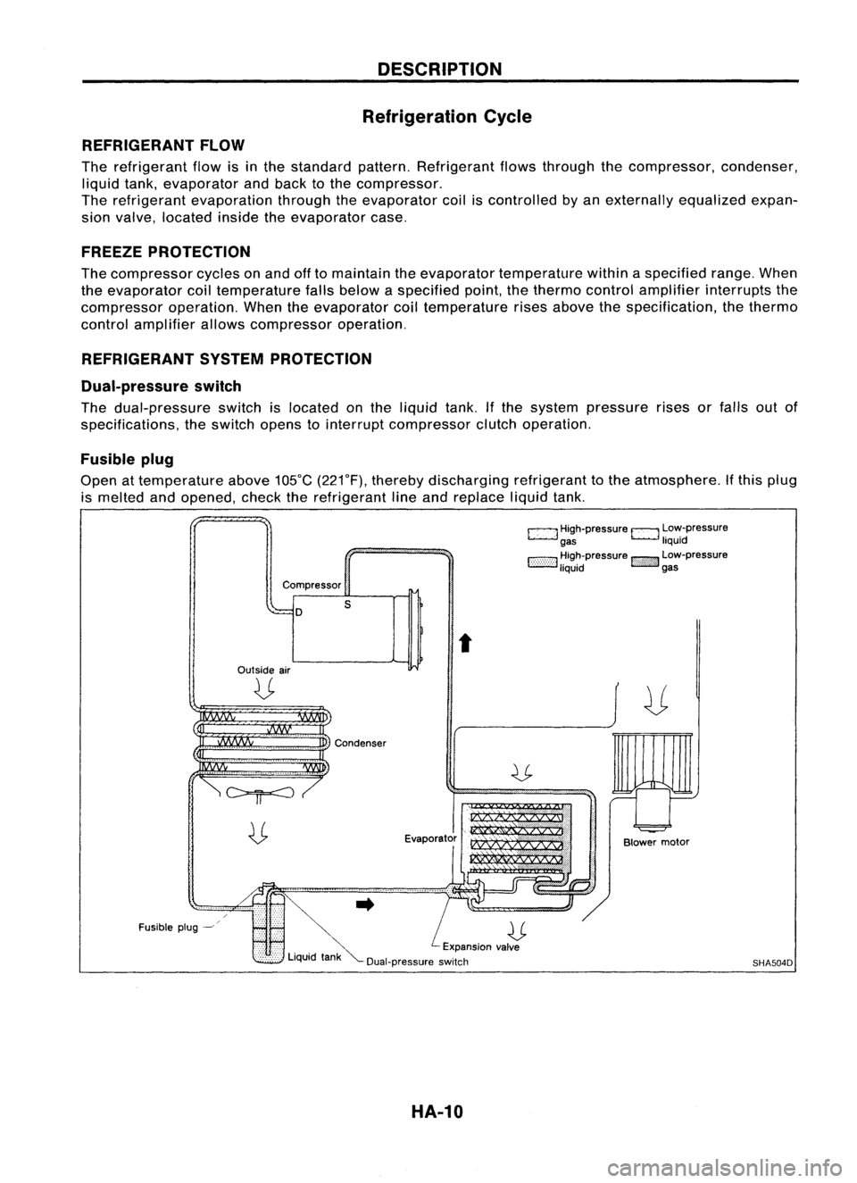
REFRIGERANT FLOW
The refrigerant flowisinthe standard pattern.Refrigerant flowsthrough thecompressor, condenser,
liquid tank,evaporator andback tothe compressor.
The refrigerant evaporation throughtheevaporator coiliscontrolled byan externally equalizedexpan-
sion valve, located insidetheevaporator case.
FREEZE PROTECTION
The compressor cyclesonand offtomaintain theevaporator temperature withinaspecified range.When
the evaporator coiltemperature fallsbelow aspecified point,thethermo controlamplifier interrupts the
compressor operation.Whentheevaporator coiltemperature risesabove thespecification, thethermo
control amplifier allowscompressor operation.
REFRIGERANT SYSTEMPROTECTION
Dual-pressure switch
The dual-pressure switchislocated onthe liquid tank.Ifthe system pressure risesorfalls outof
specifications, theswitch openstointerrupt compressor clutchoperation.
Fusible plug
Open attemperature above105°C(221°F), thereby discharging refrigeranttothe atmosphere. Ifthis plug
is melted andopened, checktherefrigerant lineand replace liquidtank.
c:::::.J
High-pressure
EJ
Low-pressure
gas liquid
1:-:-:-:-::-:-::-:-:1
~~~~pressure
!::i'i'i':}':J
~~:-pressure
Compressor
D
Outside air
U
s
t
Fusible plug-~
~..
U
'" Expansionvalve
Liquid tank"'--Dual-pressure switch
HA-10
Blower
motor
SHA504D