Page 1267 of 1701
SEM925CCYLINDER
HEAD
Disassembly (Cont'd)
12. Remove valveoilseal with asuitable tool.
Inspection
CYLINDER HEADDISTORTION
. Head surface flatness:
Standard Less than0.03mm(0.0012 in)
Limit
0.1 mm (0.004 in)
If beyond thespecified limit,replace orresurface.
Resurfacing limit:
The resurfacing limitofcylinder headisdetermined bythe cyl-
inder block resurfacing inan engine.
Amount ofcylinder headresurfacing is
"A".
Amount ofcylinder blockresurfacing is
"B".
The maximum limitisas follows:
A
+
B
=
0.2 mm (0.008 in)
After resurfacing cylinderhead,check thatcamshaft rotates
freely byhand. Ifresistance isfelt, cylinder headmustbe
replaced.
Nominal cylinderheadheight:
136.9 -137.1 mm(5.390 -5.398 in)
CAMSHAFT VISUALCHECK
Check camshaft forscratches, seizureandwear.
CAMSHAFT RUNOUT
1. Measure camshaft runoutatthe center journal.
Runout (Totalindicator reading):
Standard Less than0.02mm(0.0008 in)
Limit
0.1 mm (0.004 in)
2. Ifitexceeds thelimit, replace camshaft.
EM-88
Page 1274 of 1701
![NISSAN ALMERA N15 1995 Service Manual CYLINDERHEAD
ill]
Assembly (Cont'd)
10. Install valvecomponent parts.
• Install valves withlarger diameter headonthe intake side.
•
Wide pitch
Narrow pitch
Paint mark
Cylinder headside
S NISSAN ALMERA N15 1995 Service Manual CYLINDERHEAD
ill]
Assembly (Cont'd)
10. Install valvecomponent parts.
• Install valves withlarger diameter headonthe intake side.
•
Wide pitch
Narrow pitch
Paint mark
Cylinder headside
S](/manual-img/5/57349/w960_57349-1273.png)
CYLINDERHEAD
ill]
Assembly (Cont'd)
10. Install valvecomponent parts.
• Install valves withlarger diameter headonthe intake side.
•
Wide pitch
Narrow pitch
Paint mark
Cylinder headside
SEM085D•
Always usenew valve oilseal.
Refer toOIL SEAL REPLACEMENT.
• Before installing valveoilseal, install valvespring seat.
.' Install valvespring (uneven pitchtype) withitsnarrow
pitched sidetoward cylinder headside(paint mark).
• After installing valvecomponent parts,tapvalve stemtip
with plastic hammer toassure aproper fit.
11. Check hydraulic lashadjusters.
a. Push rocker armathydraulic lashadjuster location, andsee
if rocker armmoves. Ifitmoves atleast 1mm (0.04 in),it
indicates thatthere isair inthe high pressure chamber.
Noise willbeemitted fromhydraulic lashadjuster ifengine
is started without bleeding air.
b. Remove hydraulic lashadjuster anddipinacontainer filled
with engine oil.While pushing plungerasshown infigure,
lightly pushcheck ballusing athin rod. Airiscompletely
bled when plunger nolonger moves.
Air cannot bebled from thistype oflash adjuster byrunning the
engine.
SEM093D
• rEngine oil
- - , t-=1=i
Proper
rod
SEM772C
Rocker arm9UVide
Rock~rarm
Shim
Hydraulic
I
.,h
.dj"'"
i\\ j
12.
Install rocker arms,shims, rockerarmguides andhydrau-
lic lash adjusters.
CAUTION: Install allparts intheir original positions.
SEM202D EM-95
Page 1301 of 1701

TIMINGBELT
Camshaft TimingBelt(Cont'd)
INSPECTION
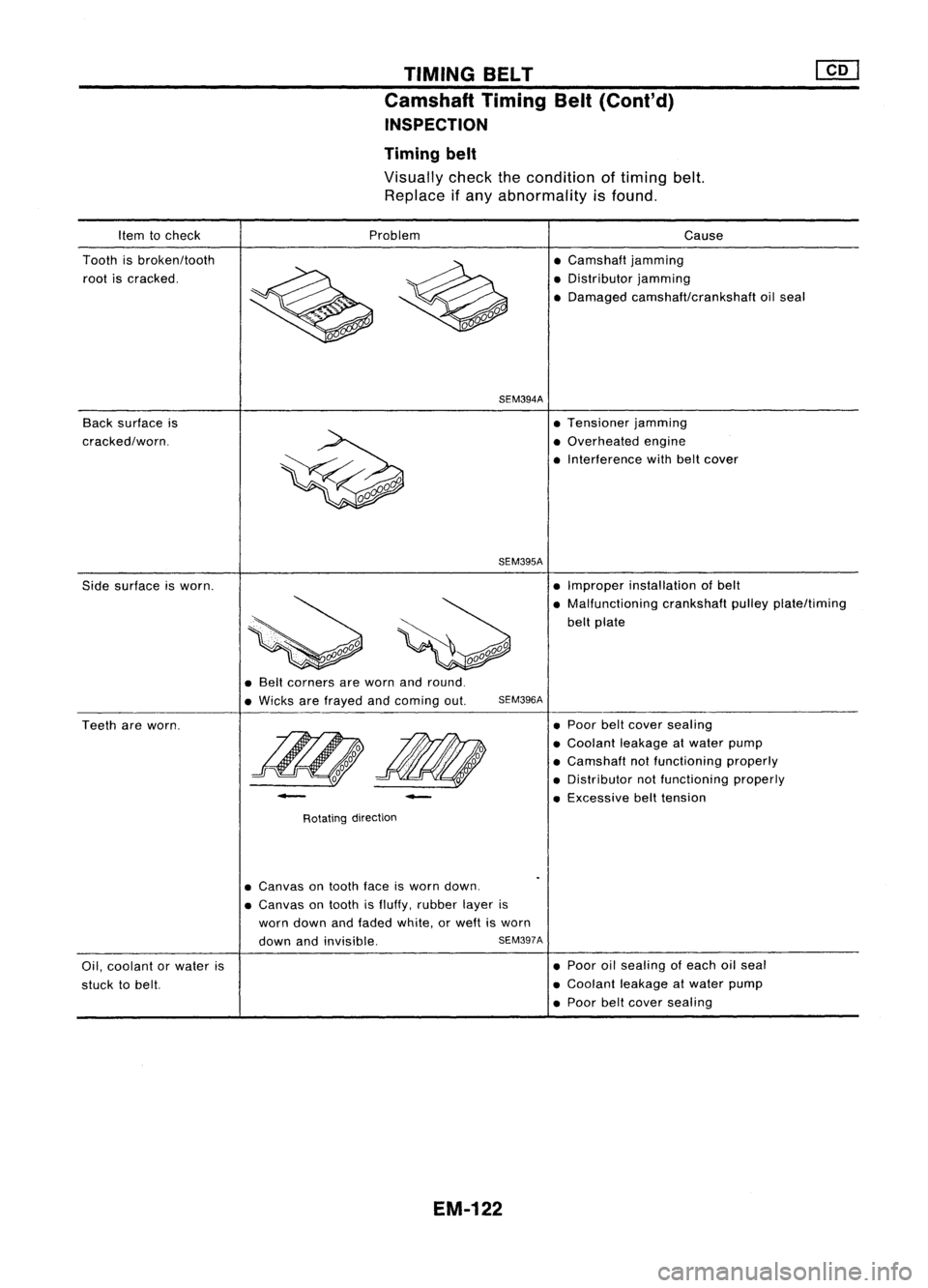
Timing belt
Visually checkthecondition oftiming belt.
Replace ifany abnormality isfound.
Item tocheck
Tooth isbroken/tooth
root iscracked.
Back surface is
cracked/worn. Problem
SEM394A
SEM395A
Cause
• Camshaft jamming
• Distributor jamming
• Damaged camshaft/crankshaft oilseal
• Tensioner jamming
• Overhe
ed
engine
• Interference withbeltcover
Side surface isworn. •
Improper installation ofbelt
• Malfunctioning crankshaftpulleyplate/timing
belt plate
• Belt corners areworn andround.
• Wicks arefrayed andcoming out.
SEM396A
Teeth areworn.
-
Rotating direction
-
•
Poor belt
cover
sealing
• Coolant leakageatwater pump
• Camshaft notfunctioning properly
• Distributor notfunctioning properly
• Excessive belttension
Oil, coolant orwater is
stuck tobelt.
•
Canvas
ontooth faceisworn down.
• Canvas
ontooth isfluffy, rubber layeris
worn down andfaded white, orweft isworn
down andinvisible.
SEM397A
EM-122
•
Poor oilsealing ofeach oilseal
• Coolant leakageatwater pump
• Poor belt
cover
sealing
Page 1309 of 1701

Warpageofsurface:
Less than0.1mm (0.004 in)
SEM595A
_ Mic~rmeter
..;- @f
l ~
--I\"
Y
'~~':-- +x
'~o
rA1-
Center
[gJ
Bottom
Valve guide Valve
SEM244D CYLINDER
HEAD
Disassembly (Cont'd)
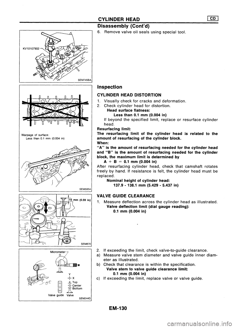
6. Remove valveoilseals usingspecial tool.
Inspection
CYLINDER HEADDISTORTION
1. Visually checkforcracks anddeformation.
2. Check cylinder headfordistortion.
Head surface flatness:
Less than0.1mm (O.004 in)
If beyond thespecified limit,replace orresurface cylinder
head.
Resurfacing limit:
The resurfacing limitofthe cylinder headisrelated tothe
amount ofresurfacing ofthe cylinder block.
When:
"A"
isthe amount ofresurfacing neededforthe cylinder head
and
"8"
isthe amount ofresurfacing neededforthe cylinder
block, themaximum limitisdetermined by
A + 8= 0.1 mm (O.004 in)
After resurfacing cylinderhead,check thatcamshaft rotates
freely byhand. Ifresistance isfelt, thecylinder headmustbe
replaced.
Nominal heightofcylinder head:
137.9. 138.1mm(5.429 .5.437 in)
VALVE GUIDECLEARANCE
1. Measure deflection acrossthecylinder headasillustrated.
Valve deflection limit(dial gauge reading):
0.1 mm (0.004 in)
2. Ifexceeding thelimit, check valve-to-guide clearance.
a) Measure valvestemdiameter andvalve guide innerdiam-
eter asillustrated.
b) Check thatclearance iswithin thespecification .
Valve stemtovalve guide clearance limit:
0.1 mm (O.004 in)
c) Ifexceeding thelimit, replace valveorvalve guide.
EM-130
Page 1310 of 1701
NGNG
SEM722BA CYLINDER
HEAD
[]Q]
Inspection (Cont'd)
VALVE GUIDEREPLACEMENT
1. Heat cylinder headinoil to150 to160°C (302to320°F).
2. Drive outvalve guide usingapress orhammer andasuit-
able tool.
3. Ream cylinder headvalve guide bore.
Reaming bore(service part):
11.185.11.196 mm(0.4404 .0.4408 in)
4. Heat cylinder headto150 to160°C (302to320°F) andpress
service valveguide ontocylinder head.
5. Ream valveguide.
Final size:
7.000 .7.015 mm(0.2756 .0.2762 in)
VALVE SEATS
1. Check valveandvalve seatforcontact.
Coat thevalve facewithprussian redlead.
If
contact is
wrong, correct valveseat.Ifthe valve redlead appears 360°
around face,thevalve stemandface areconcentric. Ifnot,
repair orreplace valve.
2. Check valveseats forpitting atcontact surface. Resurface
or replace ifexcessively worn.
Correct valveseatsurface.
When repairing valveseat,check valveandvalve guide for
wear beforehand. Ifworn, replace them.Thencorrect valve
seat.
EM-131
•
Page 1313 of 1701

SEM724B
SEM720B
WKOO"'P;O
Notch
~~~ SEM721BCYLINDER
HEAD
Inspection (Cont'd)
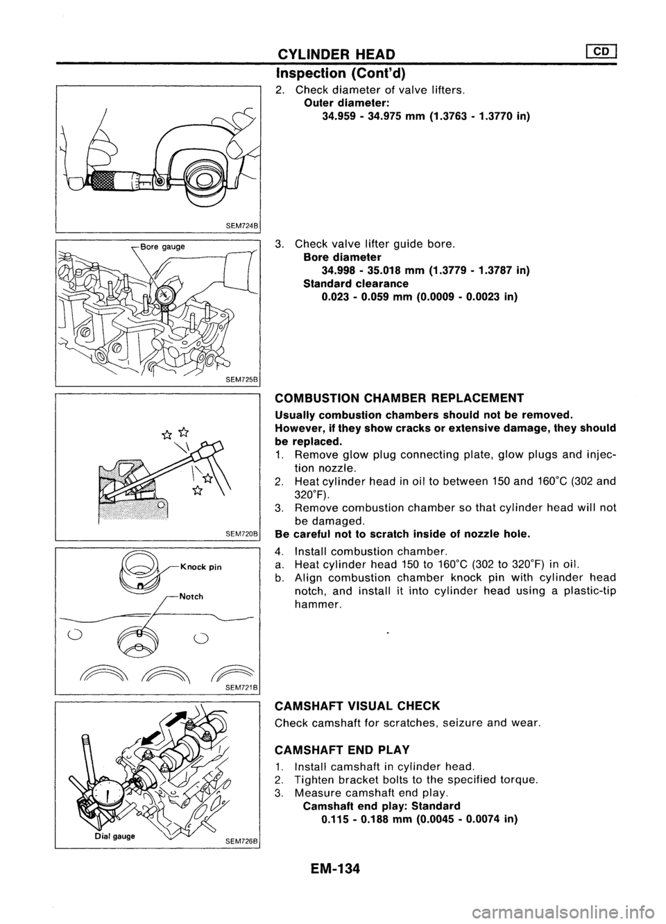
2. Check diameter ofvalve lifters.
Outer diameter:
34.959 -34.975 mm(1.3763 -1.3770 in)
3. Check valvelifterguide bore.
Bore diameter
34.998 -35.018 mm(1.3779 -1.3787 in)
Standard clearance
0.023 -0.059 mm(O.0009 -0.0023 in)
COMBUSTION CHAMBERREPLACEMENT
Usually combustion chambersshouldnotberemoved.
However, ifthey show cracks orextensive damage,theyshould
be replaced.
1. Remove glowplugconnecting plate,glowplugs andinjec-
tion nozzle.
2. Heat cylinder headinoil tobetween 150and 160°C (302and
320°F).
3. Remove combustion chambersothat cylinder headwillnot
be damaged.
Be careful nottoscratch insideofnozzle hole.
4. Install combustion chamber.
a. Heat cylinder head150to160°C (302to320°F) inoil.
b. Align combustion chamberknockpinwith cylinder head
notch, andinstall itinto cylinder headusing aplastic-tip
hammer.
CAMSHAFT VISUALCHECK
Check camshaft forscratches, seizureandwear.
CAMSHAFT ENDPLAY
1. Install camshaft incylinder head.
2. Tighten bracketboltstothe specified torque.
3. Measure camshaft endplay.
Camshaft endplay: Standard
0.115 -0.188 mm(O.0045 -0.0074 in)
EM-134
Page 1315 of 1701
![NISSAN ALMERA N15 1995 Service Manual SEM202
SEM731BA
Grade number
Tightening sequence
r
1
@@
~.~.~
o
,..0
W
@
@ @
Facing frontofengine
(position 2)
SEM528DCYLINDER
HEAD
[£Q]
Inspection {Cont'd)
4. Remove cambracket capsan NISSAN ALMERA N15 1995 Service Manual SEM202
SEM731BA
Grade number
Tightening sequence
r
1
@@
~.~.~
o
,..0
W
@
@ @
Facing frontofengine
(position 2)
SEM528DCYLINDER
HEAD
[£Q]
Inspection {Cont'd)
4. Remove cambracket capsan](/manual-img/5/57349/w960_57349-1314.png)
SEM202
SEM731BA
Grade number
Tightening sequence
r
1
@@
~.~.~
o
,..0
W
@
@ @
Facing frontofengine
(position 2)
SEM528DCYLINDER
HEAD
[£Q]
Inspection {Cont'd)
4. Remove cambracket capsandmeasure maximum widthof
plastigage. Camshaft bearingclearance:
Limit
0.1 mm (0.004 in)
5. Ifclearance appearstoexceed thelimit, replace camshaft
or cylinder head.
• Which partstobe replaced shouldbedecided uponafter
measuring thediameters ofthe parts concerned.
Assembly
1. Install valvecomponent parts.
Install valvespring withitsnarrow pitchsidetoward cylinder
head side.
• Always installnewvalve oilseals.
Refer tooil seal replacement.
• Before installing oilseal, install valve-spring seat.
• When installing valve,applyengine oilonthe valve stem
and lipofvalve oilseal.
• Check whether thevalve faceisfree from foreign matter.
• Install valvespring retainers onthe intake sideandvalve
rotators onthe exhaust side.
• Valve rotators cannotbedisassembled.
2. Install camshaft andbrackets andtighten bracket nutstothe
specified torqueintwo orthree stages.
Camshaft-bracket nuts:
~: 18-22 N'm (1.8-2.2 kg-m, 13-16 ft-Ib)
• Tighten bracketfromcenter tooutside.
• Apply sealant tobrackets No.1and No.5.
• When installing "brackets, setcamshaft sothat thepinof
camshaft fronthead isuppermost.
• Install newcamshaft oilseals.
Refer tooil seal replacement.
17.5 (0.689)
o
o
13.0
(0.512)
NO.1 journal bracket No.5journal bracket
Unit: mm(in)
SEM676D
EM-136
Page 1316 of 1701

Cylinderheadbolt
N.m (kg-m, ft-Ib)
83 -93
(8.5 -9.5,
(Iii(~)
61.2 -68.6)
39 (4.0, 29)
o
N.m (0kg-m, 0ft-Ib)
SEM673DA
SEM678D CYLINDER
HEAD
Installation
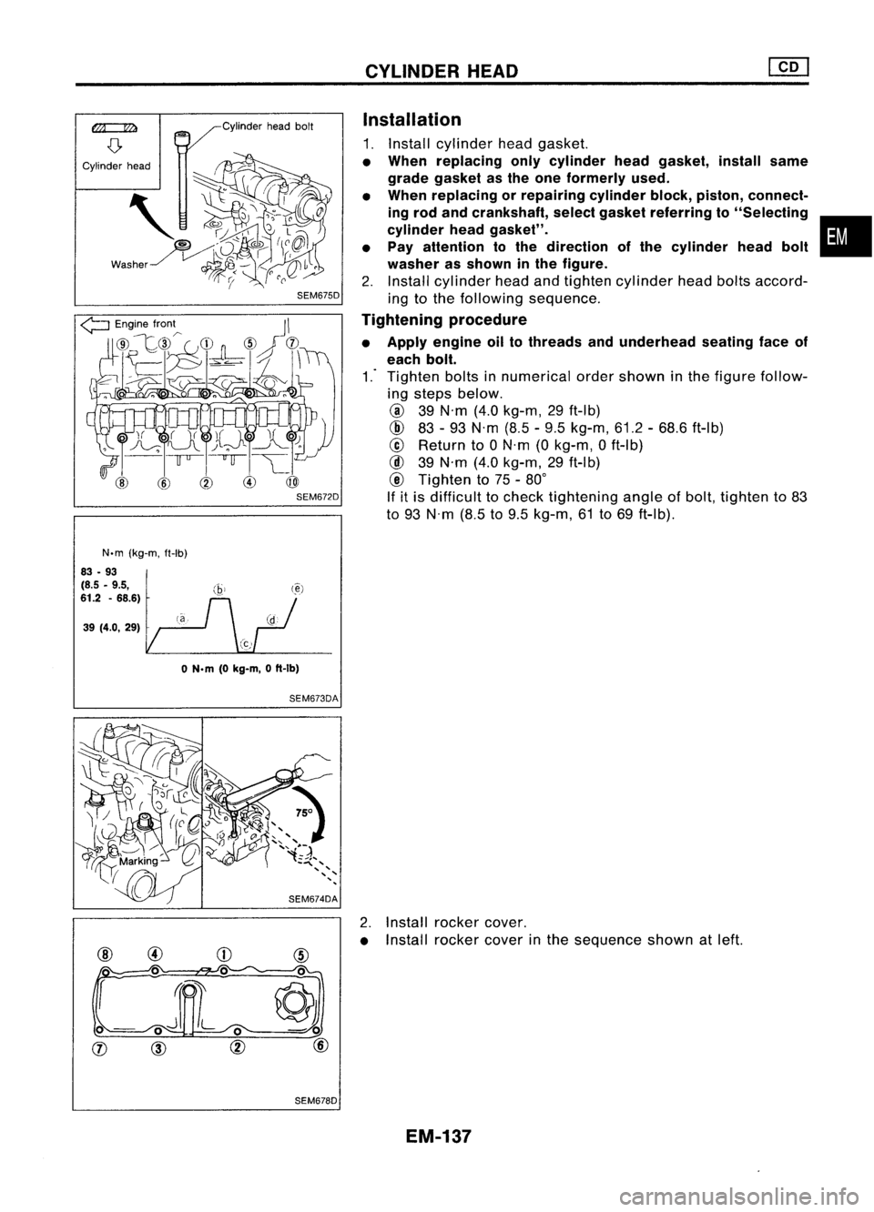
1. Install cylinder headgasket.
• When replacing onlycylinder headgasket, installsame
grade gasket asthe one formerly used.
• When replacing orrepairing cylinderblock,piston, connect-
ing rod and crankshaft, selectgasket referring to"Selecting •
cylinder headgasket".
• Pay attention tothe direction ofthe cylinder headbolt
washer asshown inthe figure.
2. Install cylinder headandtighten cylinder headboltsaccord-
ing tothe following sequence.
Tightening procedure
• Apply engine oiltothreads andunderhead seatingfaceof
each bolt.
1.-
Tighten boltsinnumerical ordershown inthe figure follow-
ing steps below.
@
39N'm (4.0kg-m, 29ft-Ib)
@
83-93 N'm (8.5-9.5 kg-m, 61.2-68.6 ft-Ib)
@
Return to0N'm (0kg-m, 0ft-Ib)
@
39N'm (4.0kg-m, 29ft-Ib)
@
Tighten to75 -80°
If itis difficult tocheck tightening angleofbolt, tighten to83
to 93 N'm (8.5to9.5 kg-m, 61to69 ft-Ib).
2. Install rocker cover.
• Install rocker coverinthe sequence shownatleft.
EM-137