Page 1205 of 1701
Intakeside
o~ ~
~NO.5~
~ ~No. 4~
~ "'DNo. 3"~
L
"\J;;\
No.2
~V~NO'
~~FronOt mark~
Front ......., TIMING
CHAIN
Installation (Cont'd)
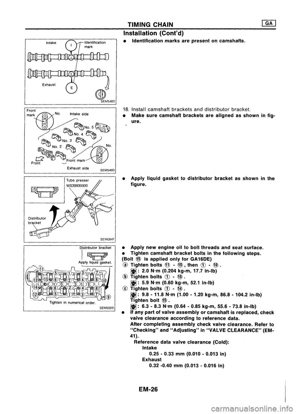
• Identification marksarepresent oncamshafts.
18. Install camshaft bracketsanddistributor bracket.
• Make surecamshaft bracketsarealigned asshown infig-
ure.
Exhaust side
SEM549D
Distributor bracket
I~
Apply liquidgasket.
@
@
@
rl~FL~~I~~~~
),i
o)(oo~-.'.-
0l1..0)(
0
~ .@/~
o'(!l@
@
cID
CD~cID
oc1)
1
0
@
Tighten innumerical order.
SEM550D
•
Apply liquidgasket todistributor bracketasshown inthe
figure.
• Apply newengine oiltobolt threads andseat surface.
• Tighten camshaft bracketboltsinthe following steps.
(Bolt
@>
isapplied onlyforGA16DE)
@
Tighten bolts
@-
@>,
then
CD-
@).
~: 2.0N'm (0.204 kg-m,17.7in-Ib)
@
Tighten bolts
CD-
@>.
~: 5.9N'm (0.60 kg-m, 52.1in-Ib)
@
Tighten bolts
CD-
@.
~: 9.8-11.8 N'm (1.00 -1.20 kg-m, 86.8-104.2 in-Ib)
Tighten bolt
@>.
~: 6.3-8.3 N'm (0.64 -0.85 kg-m, 55.6-73.8 in-Ib)
• Ifany part ofvalve assembly orcamshaft isreplaced, check
valve clearance accordingtoreference data.
After completing assemblycheckvalveclearance. Referto
"Checking" and"Adjusting" in"VALVE CLEARANCE" (EM-
41).
Reference datavalve clearance (Cold):
Intake
0.25 -0.33 mm(0.010 -0.013 in)
Exhaust
0.32 -0.40 mm(0.013 -0.016 in)
EM-26
Page 1206 of 1701
•:Mating mark(different color) 16
rollers
SEM129F TIMING
CHAIN
@K]
Installation
(Cont'd)
19. Assemble camshaftsprocketwithchain.
• Set timing chainbyaligning matingmarkswiththose of
camshaft sprockets.
• Make suresprocket's matingmarksfaceengine front.
20. Install camshaft sprocketbolts.
• Apply newengine oiltobolt threads andseat surface .
•
SEM657D
2.0.3.0
mm
(0.079 -0.118 In)
21.
Install upperchaintensioner.
• Before installing chaintensioner, insertasuitable pininto
pin hole ofchain tensioner.
• After installing chaintensioner, removethepin.
22. Install lowerchaintensioner.
CAUTION:
• Check noproblems occurwhenengine isrotated.
• Make surethatNo.1piston isset atTOC onitscompres-
sion stroke.
• Make sureofthe direction ofthe gasket beforeinstalling
lower chaintensioner.
23. Apply liquidgasket tothermostat housing.
• Use Genuine LiquidGasket orequivalent.
24. Install thermostat housing.
25. Install waterpump pulley.
EM-27
Page 1213 of 1701
CYLINDERHEAD
CAUTION:
• When installing camshaft, oilseals orother sliding parts,
lubricate contacting surfaceswithnewengine oil.
• When tightening cylinderheadbolts, camshaft sprocket
bolts andcamshaft bracketbolts,lubricate threadportions
and seat surfaces ofbolts withnewengine oil.
• Attach tagstovalve lifters soas not tomix them up.
Removal
• This removal isthe same procedure asthose fortiming
chain. Referto"Removal" in"TIMING CHAIN"(EM-20).
Disassembly
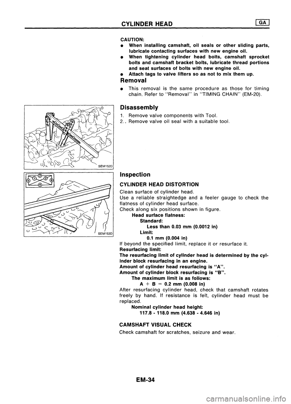
1. Remove valvecomponents withTool.
2 .. Remove valveoilseal withasuitable tool.
Inspection
CYLINDER HEADDISTORTION
Clean surface ofcylinder head.
Use areliable straightedge andafeeler gauge tocheck the
flatness ofcylinder headsurface.
Check alongsixpositions showninfigure.
Head surface flatness:
Standard:
Less than0.03mm(0.0012 in)
Limit: 0.1 mm (0.004 in)
If beyond thespecified limit,replace itor resurface it.
Resurfacing limit:
The resurfacing limitofcylinder headisdetermined bythe cyl-
inder block resurfacing inan engine.
Amount ofcylinder headresurfacing is
"A".
Amount ofcylinder blockresurfacing is
"8".
The maximum limitisas follows:
A +8
=
0.2 mm (0.008 in)
After resurfacing cylinderhead,check thatcamshaft rotates
freely byhand. Ifresistance isfelt, cylinder headmust be
replaced.
Nominal cylinderheadheight:
117.8 -118.0 mm(4.638 .4.646 in)
CAMSHAFT VISUALCHECK
Check camshaft forscratches, seizureandwear.
EM-34
Page 1219 of 1701
SEM160DCYLINDER
HEAD
Inspection (Cont'd)
VALVE LIFTER ANDVALVE SHIM
1. Check contact andsliding surfaces forwear orscratches.
SEM161D
SEM162D
2.
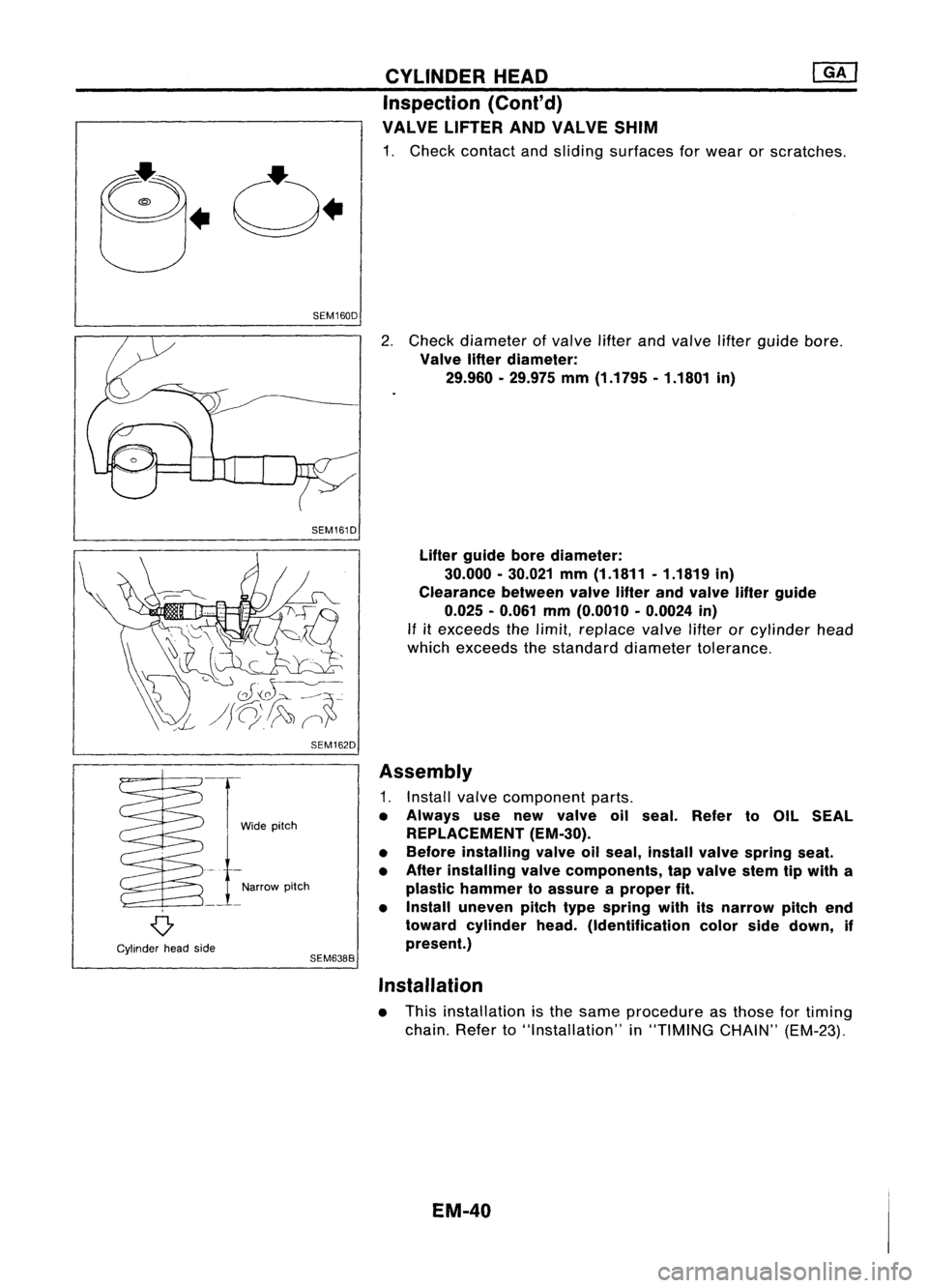
Check diameter ofvalve lifterandvalve lifterguide bore.
Valve lifterdiameter:
29.960 •29.975 mm(1.1795 •1.1801 in)
Lifter guide borediameter:
30.000 -30.021 mm(1.1811 .1.1819 in)
Clearance betweenvalvelifterandvalve lifterguide
0.025 -0.061 mm(0.0010 -0.0024 in)
If
it
exceeds thelimit, replace valvelifterorcylinder head
which exceeds thestandard diameter tolerance.
o
Cylinder headside Wide
pitch
Narrow pitch
SEM638B
Assembly
1. Install valvecomponent parts.
• Always usenew valve oilseal. Refer toOIL SEAL
REPLACEMENT (EM-30).
• Before installing valveoilseal, install valvespring seat.
• After installing valvecomponents, tapvalve stemtipwith a
plastic hammer toassure aproper fit.
• Install uneven pitchtypespring withitsnarrow pitchend
toward cylinder head.(Identification colorsidedown, if
present.)
Installation
• This installation isthe same procedure asthose fortiming
chain. Referto"Installation" in"TIMING CHAIN"(EM-23).
EM-40
Page 1228 of 1701
I
Micrometer
AEM024CYLINDER
BLOCK ~
Inspection (Conl'd)
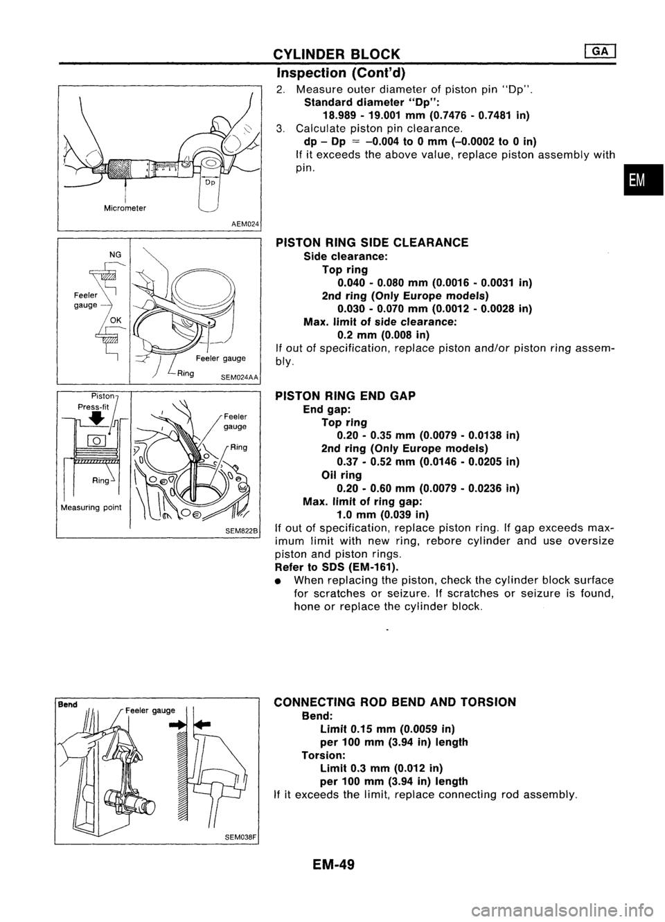
2. Measure outerdiameter ofpiston pin"Op".
Standard diameter "Op":
18.989 -19.001 mm(0.7476 -0.7481 in)
3. Calculate pistonpinclearance.
dp -Op
=
-0.004 to0mm (-0.0002 to0in)
If itexceeds theabove value, replace pistonassembly with
pin.
•
NG
Ring
Measuring point Feeler
gauge
SEM8228 PISTON
RINGSIDECLEARANCE
Side clearance:
Top ring
0.040 -0.080 mm(0.0016 -0.0031 in)
2nd ring (Only Europe models)
0.030 -0.070 mm(0.0012 -0.0028 in)
Max. limitofside clearance:
0.2 mm (0.008 in)
If out ofspecification, replacepistonand/or pistonringassem-
bly.
PISTON RINGENDGAP
End gap:
Top ring
0.20 -0.35 mm(0.0079 -0.0138 in)
2nd ring (Only Europe models)
0.37 -0.52 mm(0.0146 -0.0205 in)
Oil ring
0.20 -0.60 mm(0.0079 -0.0236 in)
Max. limitofring gap:
1.0 mm (0.039 in)
If out ofspecification, replacepistonring.Ifgap exceeds max-
imum limitwithnewring, rebore cylinder anduseoversize
piston andpiston rings.
Refer toSOS (EM-161).
• When replacing thepiston, checkthecylinder blocksurface
for scratches orseizure. Ifscratches orseizure isfound,
hone orreplace thecylinder block.
CONNECTING RODBEND ANDTORSION
Bend: Limit 0.15mm(0.0059 in)
per 100 mm (3.94 in)length
Torsion: Limit 0.3mm (0.012 in)
per 100 mm (3.94 in)length
If itexceeds thelimit, replace connecting rodassembly.
EM-49
Page 1231 of 1701
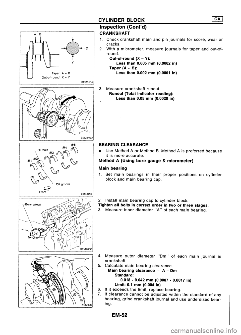
AB
Taper:A-B
Out-at-round: X-
y
Oil groove
y
SEM316A
SEM366E CYLINDER
BLOCK ~
Inspection (Cont'd)
CRANKSHAFT
1. Check crankshaft mainandpinjournals forscore, wearor
cracks.
2. With amicrometer, measurejournalsfortaper andout-of-
round.
Out-of-round (X-V):
Less than0.005 mm(O.0002 in)
Taper (A-B):
Less than0.002 mm(O.0001 in)
3. Measure crankshaft runout.
Runout (Totalindicator reading):
Less than0.05mm(O.0020 in)
BEARING CLEARANCE
• Use Method Aor Method B.Method Ais preferred because
it is more accurate.
Method A(Using boregauge µmeter)
Main bearing
1. Set main bearings intheir proper positions oncylinder
block andmain bearing cap.
2. Install mainbearing captocylinder block.
Tighten allbolts incorrect orderintwo orthree stages.
3. Measure innerdiameter "A"ofeach main bearing.
4. Measure outerdiameter "Om"ofeach mainjournal in
crankshaft.
5. Calculate mainbearing clearance.
Main bearing clearance
=
A-
Om
Standard:
0.018 .0.042 mm(O.0007 .0.0017 in)
Limit: 0.1mm (O.004 in)
6. Ifitexceeds thelimit, replace bearing.
7. Ifclearance cannotbeadjusted withinthestandard ofany
bearing, grindcrankshaft journalanduseundersized bear-
ing.
EM-52
Page 1241 of 1701
COMPRESSIONPRESSURE
Measurement ofCompression Pressure
1. Warm upengine.
2. Turn ignition switchoff.
3. Release fuelpressure.
Refer to"Releasing FuelPressure" inEC section.
4. Remove allspark plugs.
5. Disconnect distributorcoilconnector.
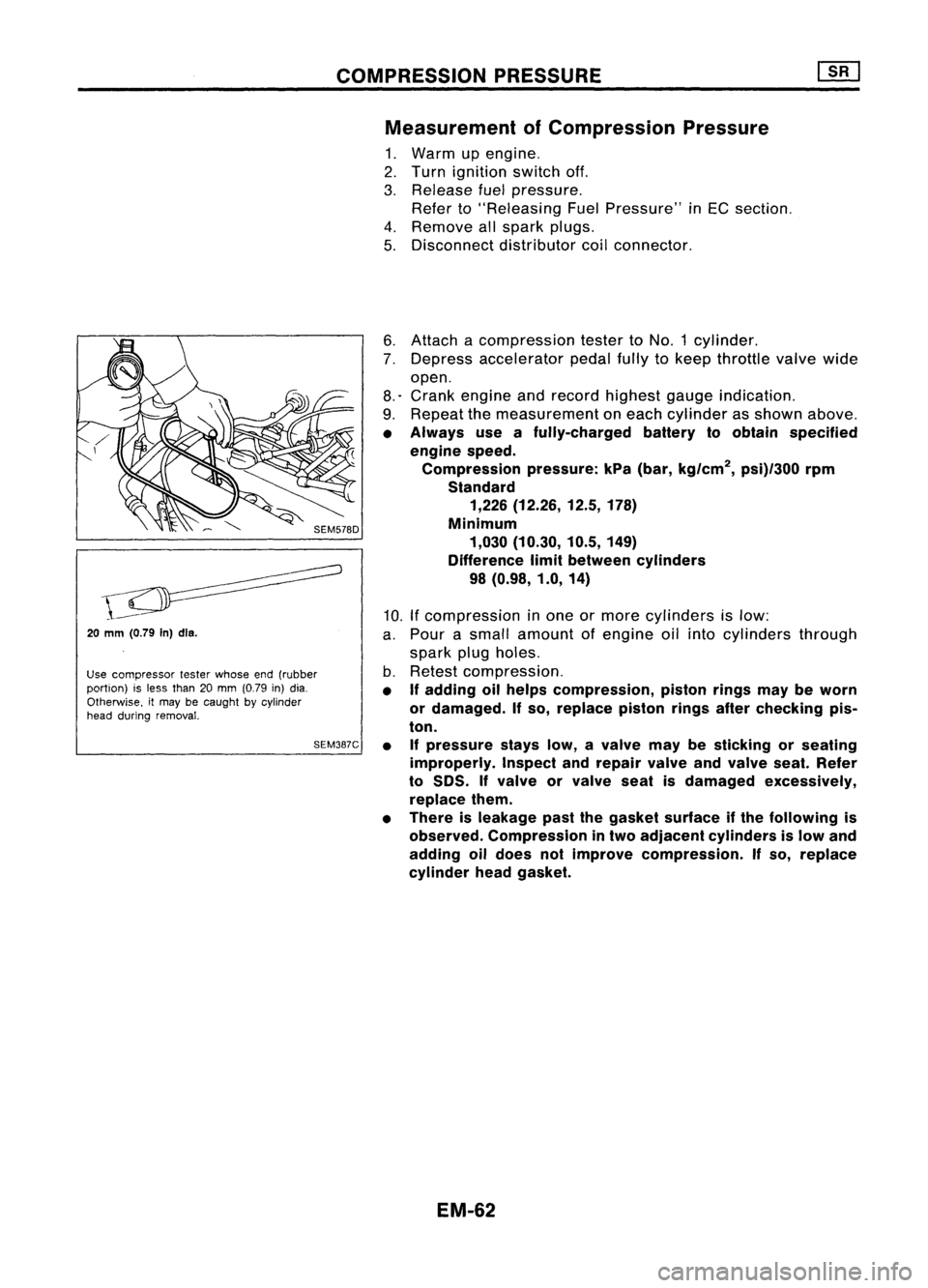
20
mm (0.79
In)dls.
Use compressor testerwhose end(rubber
portion) isless than 20mm (0.79 in)dia.
Otherwise. itmay becaught bycylinder
head during removal.
SEM387C6.
Attach acompression testertoNO.1 cylinder.
7. Depress accelerator pedalfullytokeep throttle valvewide
open.
8.' Crank engine andrecord highest gaugeindication.
9. Repeat themeasurement oneach cylinder asshown above.
• Always useafully-charged batterytoobtain specified
engine speed.
Compression pressure:kPa(bar, kg/cm
2,
psi)/300 rpm
Standard 1,226 (12.26, 12.5,178)
Minimum 1,030 (10.30, 10.5,149)
Difference limitbetween cylinders
98 (0.98, 1.0,14)
10. Ifcompression inone ormore cylinders islow:
a. Pour asmall amount ofengine oilinto cylinders through
spark plugholes.
b. Retest compression.
• If
adding oilhelps compression, pistonringsmaybeworn
or damaged.
If
so, replace pistonringsafterchecking pis-
ton.
• Ifpressure stayslow,avalve maybesticking orseating
improperly. Inspectandrepair valveandvalve seat.Refer
to
50S.
If
valve orvalve seatisdamaged excessively,
replace them.
• There isleakage pastthegasket surface ifthe following is
observed. Compression intwo adjacent cylinders islow and
adding oildoes notimprove compression.
If
so, replace
cylinder headgasket.
EM-62
Page 1252 of 1701
Engine~
front
Y--J
SEM721E
SEM984C
~ Crankshaft
!..--..V
side
Crankshaft sprocket
SEM470E TIMING
CHAIN
Removal (Cont'd)
30. Remove frontengine mounting.
31. Remove frontcover andoilpump drivespacer.
• Inspect foroilleakage atfront oilseal. Replace sealifoil
leak ispresent.
32. Remove timingchainguides andtiming chain.
Inspection
Check forcracks andexcessive wearatroller links.Replace
chain ifnecessary.
Installation
1. Install crankshaft sprocketoncrankshaft.
• Make surethatmating marksoncrankshaft sprocketface
front ofengine.
EM-73
•