Page 868 of 1771

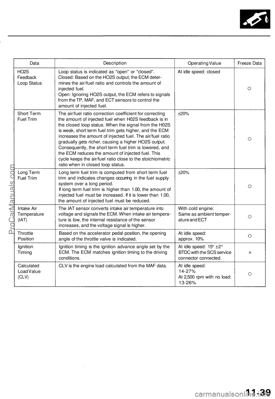
Data
Description
Operating Value
Freeze Data
HO2S
Feedback
Loop Status
Loop status is indicated as "open" or "closed".
Closed: Based on the HO2S output, the ECM deter-
mines the air/fuel ratio and controls the amount of
injected fuel.
Open: Ignoring HO2S output, the ECM refers to signals
from the TP, MAF, and ECT sensors to control the
amount of injected fuel.
At idle speed: closed
Short Term
Fuel Trim
The air/fuel ratio correction coefficient for correcting
the amount of injected fuel when H02S feedback is in
the closed loop status. When the signal from the H02S
is weak, short term fuel trim gets higher, and the ECM
increases the amount of injected fuel. The air/fuel ratio
gradually gets richer, causing a higher HO2S output.
Consequently, the short term fuel trim is lowered, and
the ECM reduces the amount of injected fuel. This
cycle keeps the air/fuel ratio close to the stoichiometric
ratio when in closed loop status.
±20%
Long Term
Fuel Trim
Long term fuel trim is computed from short term fuel
trim and indicates changes occurring in the fuel supply
system over a long period.
If long term fuel trim is higher than 1.00, the amount of
injected fuel must be increased. If it is lower than 1.00,
the amount of injected fuel must be reduced.
±20%
Intake Air
Temperature
(IAT)
The IAT sensor converts intake air temperature into
voltage and signals the ECM. When intake air tempera-
ture is low, the internal resistance of the sensor
increases, and the voltage signal is higher.
With cold engine:
Same as ambient temper-
ature and ECT
Throttle
Position
Based on the accelerator pedal position, the opening
angle of the throttle valve is indicated.
At idle speed:
approx. 10%
Ignition
Timing
Ignition timing is the ignition advance angle set by the
ECM. The ECM matches ignition timing to the driving
conditions.
At idle speed: 15° ±2°
BTDC with the SCS service
connector connected.
Calculated
Load Value
(CLV)
CLV is the engine load calculated from the MAF data.
At idle speed:
14-27%
At 2,500 rpm with no load:
13-26%ProCarManuals.com
Page 903 of 1771

Fuel Supply System
Fuel Pressure
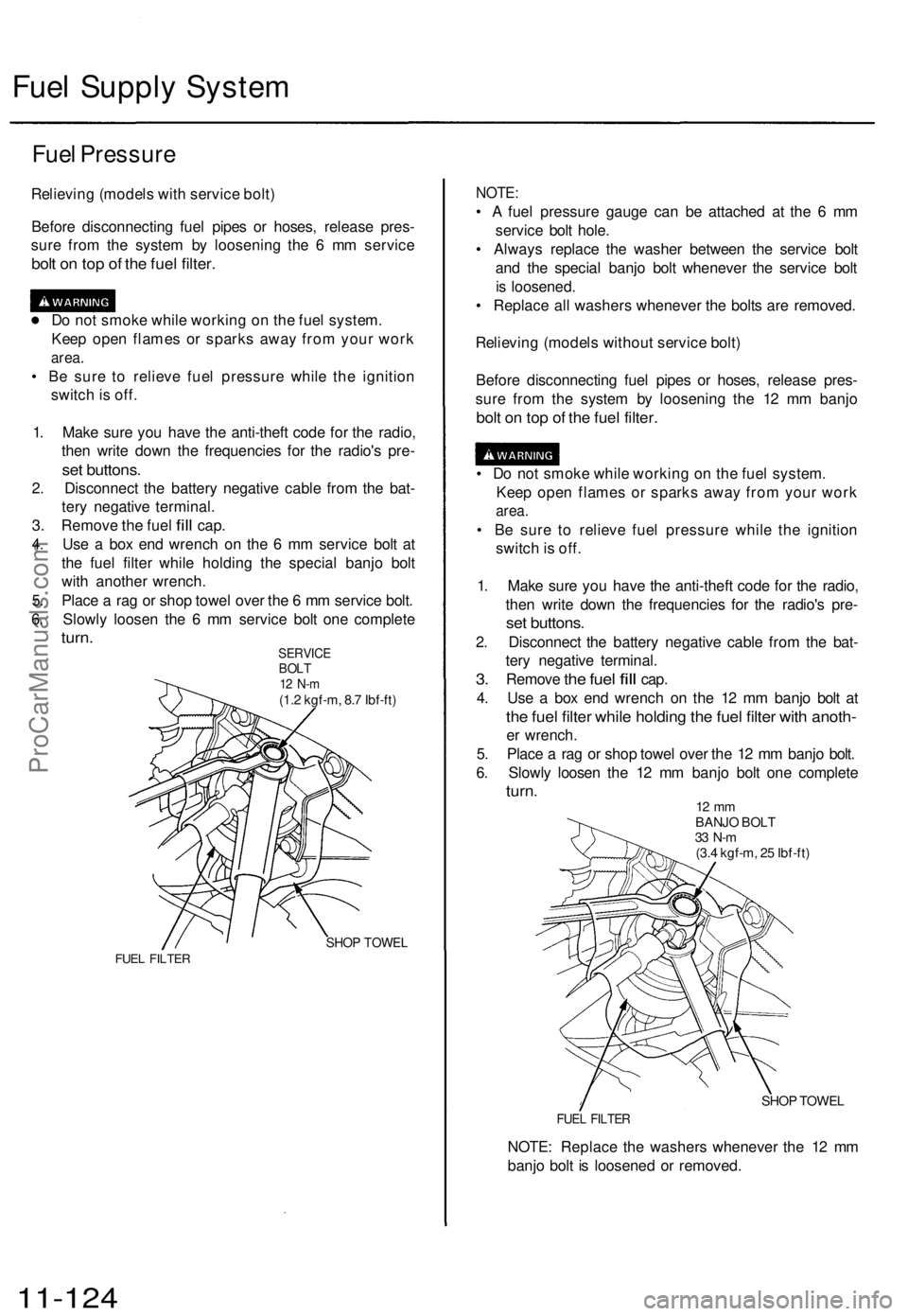
Relieving (models with service bolt)
Before disconnecting fuel pipes or hoses, release pres-
sure from the system by loosening the 6 mm service
bolt on top of the fuel filter.
Do not smoke while working on the fuel system.
Keep open flames or sparks away from your work
area.
• Be sure to relieve fuel pressure while the ignition
switch is off.
1. Make sure you have the anti-theft code for the radio,
then write down the frequencies for the radio's pre-
set buttons.
2. Disconnect the battery negative cable from the bat-
tery negative terminal.
3.
Remove
the
fuel
fill
cap.
4. Use a box end wrench on the 6 mm service bolt at
the fuel filter while holding the special banjo bolt
with another wrench.
5. Place a rag or shop towel over the 6 mm service bolt.
6. Slowly loosen the 6 mm service bolt one complete
turn.
SERVICE
BOLT
12 N-m
(1.2 kgf-m, 8.7 Ibf-ft)
SHOP TOWEL
FUEL FILTER
NOTE:
• A fuel pressure gauge can be attached at the 6 mm
service bolt hole.
• Always replace the washer between the service bolt
and the special banjo bolt whenever the service bolt
is loosened.
• Replace all washers whenever the bolts are removed.
Relieving (models without service bolt)
Before disconnecting fuel pipes or hoses, release pres-
sure from the system by loosening the 12 mm banjo
bolt on top of the fuel filter.
• Do not smoke while working on the fuel system.
Keep open flames or sparks away from your work
area.
• Be sure to relieve fuel pressure while the ignition
switch is off.
1. Make sure you have the anti-theft code for the radio,
then write down the frequencies for the radio's pre-
set buttons.
2. Disconnect the battery negative cable from the bat-
tery negative terminal.
3.
Remove
the
fuel
fill
cap.
4. Use a box end wrench on the 12 mm banjo bolt at
the fuel filter while holding the fuel filter with anoth-
er wrench.
5. Place a rag or shop towel over the 12 mm banjo bolt.
6. Slowly loosen the 12 mm banjo bolt one complete
turn.
12 mm
BANJO BOLT
33 N-m
(3.4 kgf-m, 25 Ibf-ft)
SHOP TOWEL
FUEL FILTER
NOTE: Replace the washers whenever the 12 mm
banjo bolt is loosened or removed.
11-124ProCarManuals.com
Page 911 of 1771
Fuel Supply System
Fuel Filter (cont'd)
Models with service bolt:
SPECIAL BOLT
27
N-m
(2.8
kgf-m,
20
Ibf-ft)
SERVICE BOLT
12N-m(1.2kgf-n
8.7
Ibf-ft)
WASHERS
Replace.
37
N-m
(3.8
kgf-m,
27
Ibf-ft)
9.8
N-m
(1.0
kgf-m,
7.2
Ibf-ft)
Models without service bolt:
9.8
N-m
(1.0
kgf-m,
7.2
Ibf-ft)
12mm
BANJO BOLT
33
N-m
(3.4
kgf-m,
25
Ibf-ft)
WASHER
Replace.
37
N-m
(3.8
kgf-m,
27
Ibf-ft)ProCarManuals.com
Page 951 of 1771
Description
The electronic control system consists of the Transmission Control Module (TCM), sensors, a linear solenoid, and four
solenoid valves.
Shift and lock-up are electronically controlled for comfortable driving under all conditions.
The TCM is located below the dashboard, behind the glove box on the passenger's side.
TCM
Linear Solenoid
Shift Control
Solenoid Valve A
Shift Control
Solenoid Valve B
Lock-up Control
Solenoid Valve A
Lock-up Control
Solenoid Valve B
Engine Speed Signal
Brake Switch Signal
Mainshaft Speed Sensor
Signal
Countershaft Speed
Sensor Signal
Vehicle Speed Sensor
Signal
Indicator Light
Self-Diagnosis Signal
Electronic Control System
Shift Control
Lock-up Control
Throttle Position
Sensor Signal
Engine Coolant
Temperature
Sensor Signal
Service Check
Connector
Barometric
Pressure Sensor
INTERLOCK
CONTROL UNIT
Self-Diagnosis
FunctionProCarManuals.com
Page 976 of 1771

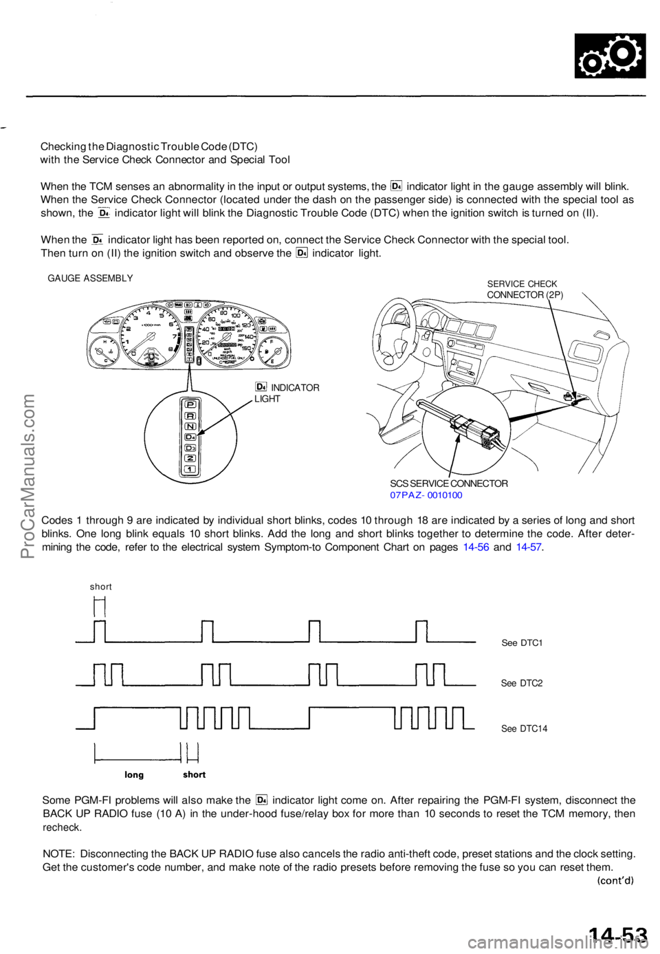
Checking th e Diagnosti c Troubl e Cod e (DTC )
wit h th e Servic e Chec k Connecto r an d Specia l Too l
Whe n th e TC M sense s a n abnormalit y in th e inpu t o r outpu t systems , th e indicato r ligh t i n th e gaug e assembl y wil l blink .
Whe n th e Servic e Chec k Connecto r (locate d unde r th e das h o n th e passenge r side ) i s connecte d wit h th e specia l too l a s
shown , th e indicato r ligh t wil l blin k th e Diagnosti c Troubl e Cod e (DTC ) whe n th e ignitio n switc h is turne d o n (II) .
Whe n th e indicato r ligh t ha s bee n reporte d on , connec t th e Servic e Chec k Connecto r wit h th e specia l tool .
Then tur n o n (II ) th e ignitio n switc h an d observ e th e indicato r light .
GAUG E ASSEMBL YSERVICE CHEC KCONNECTO R (2P )
INDICATO RLIGHT
SCS SERVIC E CONNECTO R07PAZ- 001010 0
Codes 1 throug h 9 ar e indicate d b y individua l shor t blinks , code s 1 0 throug h 1 8 ar e indicate d b y a serie s o f lon g an d shor t
blinks . On e lon g blin k equal s 1 0 shor t blinks . Ad d th e lon g an d shor t blink s togethe r t o determin e th e code . Afte r deter -
minin g th e code , refe r t o th e electrica l syste m Symptom-t o Componen t Char t o n page s 14-5 6 an d 14-57 .
short
Some PGM-F I problem s wil l als o mak e th e indicato r ligh t com e on . Afte r repairin g th e PGM-F I system , disconnec t th e
BAC K U P RADI O fus e (1 0 A ) i n th e under-hoo d fuse/rela y bo x fo r mor e tha n 1 0 second s t o rese t th e TC M memory , the n
recheck .
NOTE: Disconnectin g th e BAC K U P RADI O fus e als o cancel s th e radi o anti-theft code, prese t station s an d th e cloc k setting .
Ge t th e customer' s cod e number , an d mak e not e o f th e radi o preset s befor e removin g th e fus e s o yo u ca n rese t them .
See DTC 1
See DTC 2
See DTC1 4
ProCarManuals.com
Page 977 of 1771
Troubleshooting Procedure s
(cont'd)
SRS component s ar e locate d in thi s area . Revie w th e SR S
componen t locations , precautions , an d procedure s in th e
SR S (sectio n 24 ) befor e performin g repair s o r service .
1. Remov e th e glov e bo x fro m th e dashboard .
CLIP
GLOV E BO X
5. 0 m m BOLT S
2.Remov e th e AB S contro l uni t mountin g bolts , an d
tur n th e AB S contro l uni t over . Disconnec t th e radi -
ato r fa n time r contro l uni t connecter .
NOTE: D o no t disconnec t th e connector s fro m th e
AB S contro l unit .
ABS CONTRO LUNIT
RADIATO R FA N
CONTRO L
MODULE CONNECTO R
6 x 1. 0 m m9.8 N- m (1. 0 kgf-m ,
7. 2 Ibf-ft )
3. Remov e th e contro l uni t bracket , the n remov e th e
TCM .
6 x 1. 0 m m9.8 N- m (1. 0 kgf-m , 7. 2 Ibf-ft )
WIR E HARNES S
CONNECTO R
STUD BOL T
CONTRO L UNI TBRACKE T
TCMFLANG ENUT9.8 N- m (1. 0 kgf-m ,
7. 2 Ibf-ft )
ProCarManuals.com
Page 986 of 1771
Transmission Contro l Modul e (TCM )
Replacemen t
SRS component s ar e locate d in thi s area . Revie w th e SR S
componen t locations , precautions , an d procedure s i n th e
SR S (sectio n 24 ) befor e performin g repair s o r service .
1 . Remov e th e glov e bo x fro m th e dashboard .
CLIP
GLOV E BO X
2.
5. 0 m m BOLT S
Remov e th e AB S contro l uni t mountin g bolts , an d
tur n th e AB S contro l uni t over . Disconnec t th e radi -
ato r fa n time r contro l uni t connector .
NOTE : D o no t disconnec t th e connector s fro m th e
AB S contro l unit .
ABS CONTRO LUNIT
RADIATO R FA N
TIME R CONTRO L
UNIT CONNECTO R
6 x 1. 0 m m9.8 N- m(1.0 kgf-m , 7. 2 Ibf-ft )
3. Remov e th e contro l uni t bracket , the n remov e th e
TCM . Disconnec t th e connector s an d replac e th e
TCM .
6 x 1. 0 m m9.8 N- m (1. 0 kgf-m , 7. 2 Ibf-ft )
WIR E HARNES S
CONNECTO R
STUD BOL TFLANG E NU T
9. 8 N- m (1. 0 kgf-m ,
7. 2 Ibf-ft )
CONTRO L UNI TBRACKE T
TCM
ProCarManuals.com
Page 993 of 1771

Road Tes t
NOTE : War m u p th e engin e to norma l operatin g temperatur e (th e radiato r fa n come s on) .
1. Appl y parkin g brak e an d bloc k th e wheels . Star t th e engine , the n shif t t o positio n whil e depressin g th e brak e
pedal . Depres s th e accelerato r peda l an d releas e it suddenly . Th e engine should no t stall .
2. Repea t sam e tes t i n position .
3. Shif t t o position , an d chec k tha t th e shif t point s o n a fla t roa d occu r a t th e approximat e speed s show n o n th e nex t
page . Als o chec k fo r abnorma l nois e an d clutc h slippage .
NOTE : Throttl e positio n senso r voltag e represent s th e throttl e opening .
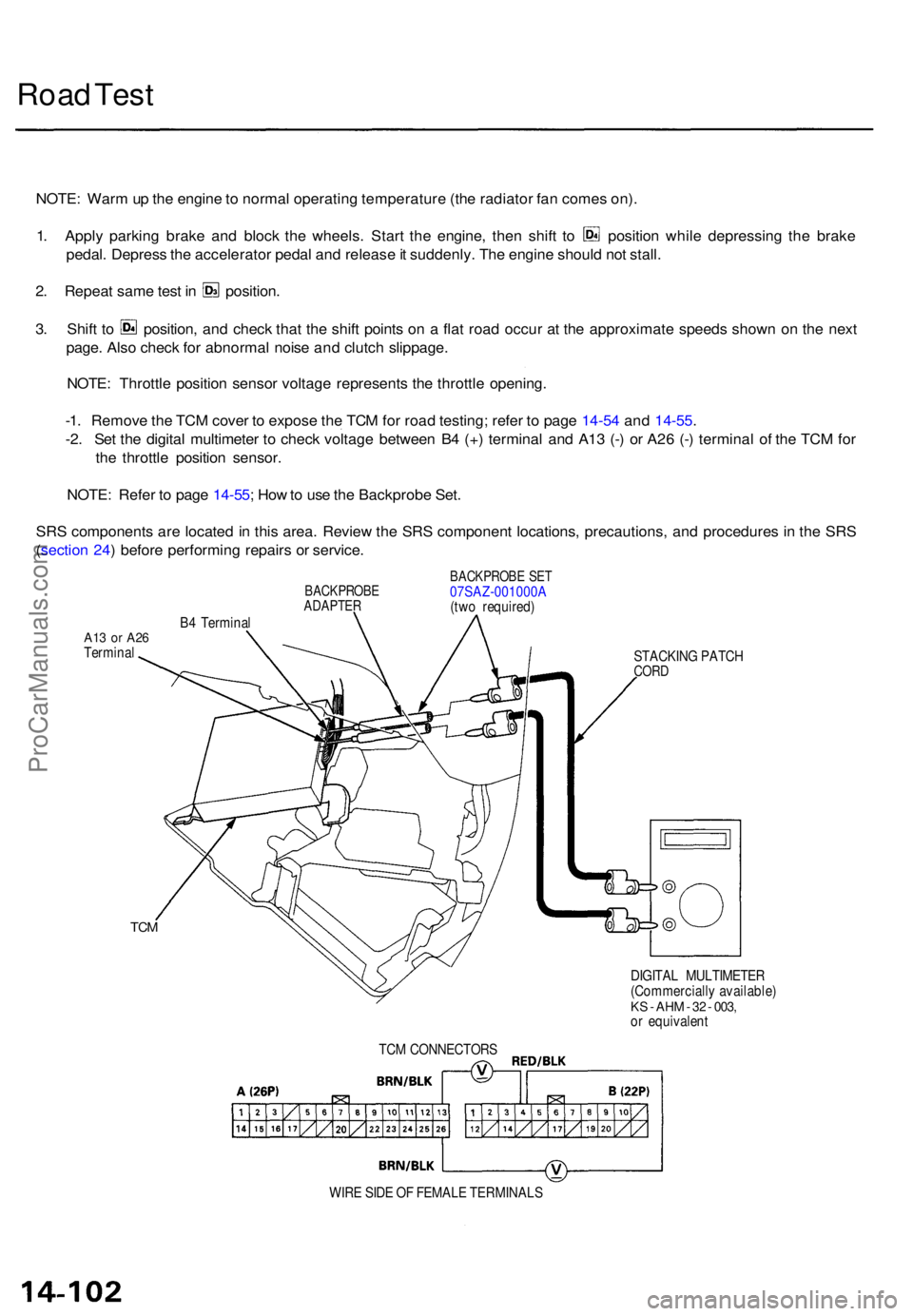
-1 . Remov e th e TC M cove r t o expos e th e TC M fo r roa d testing ; refe r t o pag e 14-5 4 an d 14-55 .
-2 . Se t th e digita l multimete r t o chec k voltag e betwee n B 4 (+ ) termina l an d A1 3 (- ) o r A2 6 (- ) termina l o f th e TC M fo r
th e throttl e positio n sensor .
NOTE : Refe r t o pag e 14-55 ; Ho w to us e th e Backprob e Set .
SR S component s ar e locate d in thi s area . Revie w th e SR S componen t locations , precautions , an d procedure s i n th e SR S
( sectio n 24 ) befor e performin g repair s o r service .
BACKPROB EADAPTER
B4 Termina l
BACKPROB E SE T07SAZ-001000 A
(tw o required )
A13 o r A2 6Termina l
STACKING PATC H
CORD
TCM
DIGITA L MULTIMETE R
(Commerciall y available )
KS - AH M - 3 2 - 003 ,or equivalen t
TC M CONNECTOR S
WIR E SID E O F FEMAL E TERMINAL S
ProCarManuals.com