1995 ACURA TL power steering
[x] Cancel search: power steeringPage 28 of 1771

Lubrication Points
For the details of lubrication points and types of lubricants to be applied, refer to the illustrated index and various work
procedures (such as Assembly/Reassembly, Replacement, Overhaul, Installation, etc.) contained in each section.
No.
1
2
3
4
5
6
7
8
9
10
11
12
13
14
15
16
17
18
19
20
21
LUBRICATION POINTS
Engine
Transmission
Brake Line (Includes Anti-lock brake line)
Power steering gearbox
Steering boots
Throttle cable end
Steering ball joints
Shift lever (Automatic transmission)
Pedal linkage
Intermediate shaft
Brake master cylinder pushrod
Fuel
fill
lid
Trunk hinges
Door hinges upper and lower
Door opening detents
Hood hinges and hood latch
Brake pipe joint (Front and rear wheel house)
Caliper Piston seal, Dust seal,
Caliper pin, Piston
Power steering system
Differential
A/C compressor
LUBRICANT
API Service Grade: Use SH "Energy Conserving II" or SJ
"Energy Conserving" grade oil.
The oil container may also display the API Certification
mark shown below. Make sure it says "For Gasoline
Engines."
SAE Viscosity: See chart below.
Genuine Honda Premium Formula Automatic
Transmission Fluid (ATF)*1
Genuine Honda DOT3 Brake Fluid*2
Steering grease P/N 08733 - B070E
Multi-purpose grease
Honda White Lithium Grease
Rust preventives
Silicone grease
Genuine Honda Power Steering Fluid-V or S*3
Hypoid gear Oil API service GL4 or GL5
Viscosity:
at above -18°C (0°F): SAE 90
at less than -18°C (0°F): SAE 80 W-90
Compressor oil:
DENSO: ND-OIL8 (P/N 38897 - PR7 - A01 AH or 38899 -
PR7-A01)
(For Refrigerant: HFC-134a (R-134a))
API SERVICE LABEL
API CERTIFICATION MARK
Recommended Engine Oil
Engine oil viscosity for ambient temperature ranges
NOTE: The following information as marked *1, *2 and *3 on above chart details for 1997 model:
*1: Always use Genuine Honda Premium Formula Automatic Transmission Fluid (ATF). Using a non-Honda ATF can affect
shift quality.
*2: Always use Genuine Honda DOT3 Brake Fluid. Using a non-Honda brake fluid can cause corrosion and decrease the
life of the system.
*3: Always use Genuine Honda Power Steering Fluid-V or S. Using any other type of power steering fluid or automatic
transmission fluid can cause increase wear and poor steering in cold weather.ProCarManuals.com
Page 45 of 1771
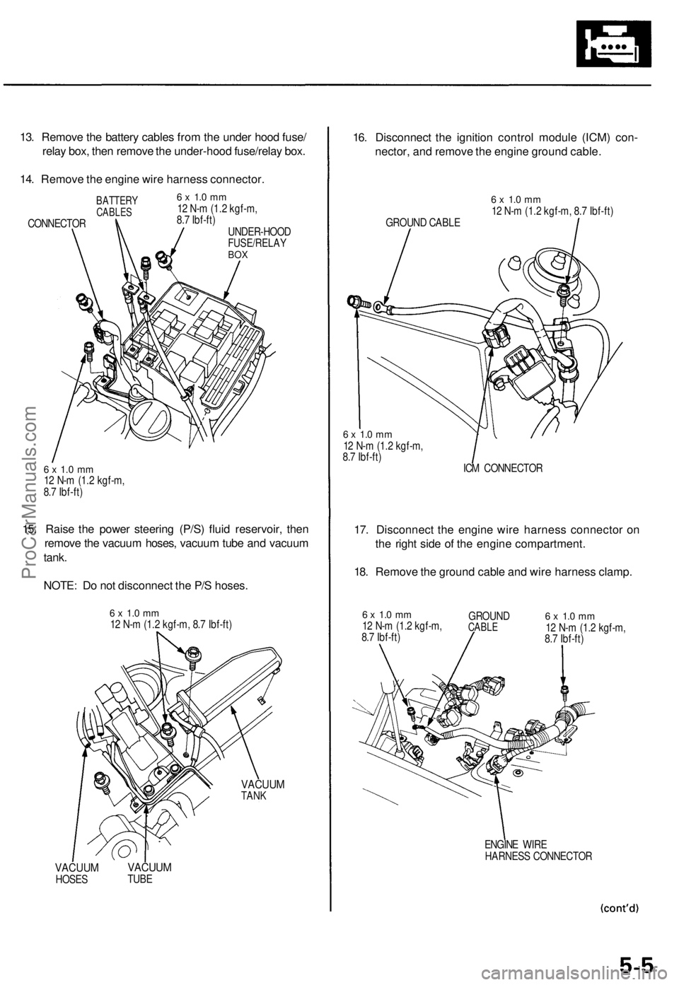
13. Remove the battery cables from the under hood fuse/
relay box, then remove the under-hood fuse/relay box.
14. Remove the engine wire harness connector.
BATTERY
CABLES
CONNECTOR
6 x 1.0 mm
12 N-m (1.2 kgf-m,
8.7 Ibf-ft)
UNDER-HOOD
FUSE/RELAY
BOX
6 x 1.0 mm
12 N-m (1.2 kgf-m,
8.7 Ibf-ft)
15. Raise the power steering (P/S) fluid reservoir, then
remove the vacuum hoses, vacuum tube and vacuum
tank.
NOTE: Do not disconnect the P/S hoses.
6 x 1.0 mm
12 N-m (1.2 kgf-m, 8.7 Ibf-ft)
VACUUM
TANK
VACUUM
HOSES
VACUUM
TUBE
16. Disconnect the ignition control module (ICM) con-
nector, and remove the engine ground cable.
GROUND CABLE
6 x 1.0 mm
12 N-m (1.2 kgf-m, 8.7 Ibf-ft)
6 x 1.0 mm
12 N-m (1.2 kgf-m,
8.7 Ibf-ft)
ICM CONNECTOR
17. Disconnect the engine wire harness connector on
the right side of the engine compartment.
18. Remove the ground cable and wire harness clamp.
6 x 1.0 mm
12 N-m (1.2 kgf-m,
8.7 Ibf-ft)
GROUND
CABLE
6 x 1.0 mm
12 N-m (1.2 kgf-m,
8.7 Ibf-ft)
ENGINE WIRE
HARNESS CONNECTORProCarManuals.com
Page 47 of 1771

25. Loosen the mounting bolt, lock bolt and adjusting
rod, then remove the alternator belt.
ADJUSTING
ROD
LOCK BOLT
8 x
1.25
mm
22 N-m (2.2 kgf-m,
16 Ibf-ft)
ALTERNATOR
BELT
MOUNTING BOLT
10 x
1.25
mm
44 N-m (4.5 kgf-m,
33 Ibf-ft)
26. Loosen the idler pulley center nut and adjusting bolt,
then remove the air conditioning (A/C) compressor
belt.
IDLER PULLEY
CENTER NUT
10 x
1.25
mm
44 N-m (4.5 kgf-m,
33 Ibf-ft)
ADJUSTING
BOLT
A/C COMPRESSOR
BELT
27. Disconnect the power steering pressure (PSP)
switch connector.
28. Remove the adjusting bolt, locknut and mounting
bolt, then remove the P/S pump belt and pump.
Do not disconnect the P/S hose.
ADJUSTING
BOLT
P/S PUMP
LOCKNUT
8 x
1.25
mm
22 N-m (2.2 kgf-m,
16 Ibf-ft)
PSP SWITCH
CONNECTOR
29.
P/S PUMP
BELT
MOUNTING BOLT
10 x
1.25
mm
44 N-m (4.5 kgf-m, 33 Ibf-ft)
Pull the carpet back to expose the secondary heated
oxygen sensor (Secondary HO2S) connector, then
disconnect the secondary HO2S connector.
SECONDARY
HO2S CONNECTORProCarManuals.com
Page 49 of 1771

41. Disconnect the vehicle speed sensor (VSS) connec-
tor, then remove the VSS/power steering speed
sensor.
Do not disconnect the fluid hoses.
6 x 1.0 mm
12 N-m (1.2 kgf-m,
8.7 Ibf-ft)
VSS CONNECTOR
VSS/POWER STEERING
SPEED SENSOR
42. Remove the heat shields from exhaust pipe A.
HEAT
SHIELDS
6 x 1.0 mm
12 N-m (1.2 kgf-m,
8.7 Ibf-ft)
43. Remove exhaust pipe A.
EXHAUST
PIPE A
GASKET
Replace.
SELF-LOCKING NUT
8 x
1.25
mm
22 N-m (2.2 kgf-m, 16 Ibf-ft)
Replace.
GASKETS
Replace.
GASKET
Replace.
TWC
6 x 1.0 mm
9.8 N-m (1.0 kgf-m,
7.2 Ibf-ft)
SELF-LOCKING NUT
8 x
1.25
mm
22 N-m (2.2 kgf-m,
16 Ibf-ft)
Replace.
SELF-LOCKING NUTS
10 x
1.25
mm
54 N-m (5.5 kgf-m,
40 Ibf-ft)
Replace.
44. Remove the wire harness cover and grommet, then
remove the three way catalytic converter (TWC).
SELF-LOCKING NUT
10 x
1.25
mm
32 N-m (3.3 kgf-m,
24 Ibf-ft)
Replace.
GROMMET
WIRE HARNESS
COVERProCarManuals.com
Page 468 of 1771
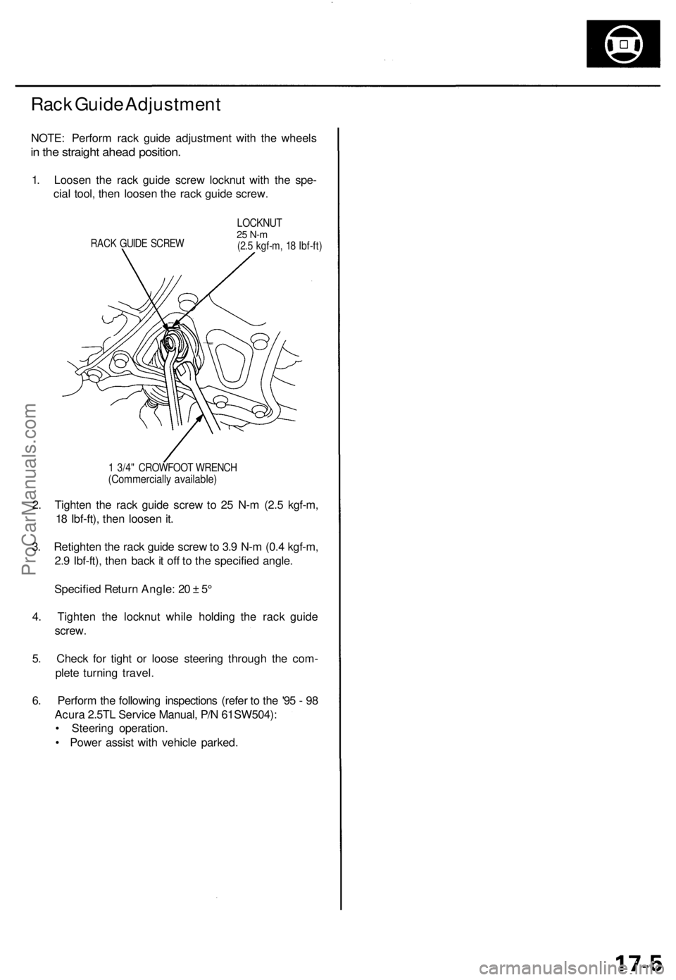
Rack Guide Adjustment
NOTE: Perform rack guide adjustment with the wheels
in the straight ahead position.
1. Loosen the rack guide screw locknut with the spe-
cial tool, then loosen the rack guide screw.
RACK GUIDE SCREW
LOCKNUT
25 N-m
(2.5 kgf-m, 18 Ibf-ft)
1 3/4" CROWFOOT WRENCH
(Commercially available)
2. Tighten the rack guide screw to 25 N-m (2.5 kgf-m,
18 Ibf-ft), then loosen it.
3. Retighten the rack guide screw to 3.9 N-m (0.4 kgf-m,
2.9 Ibf-ft), then back it off to the specified angle.
Specified Return Angle: 20 ± 5°
4. Tighten the locknut while holding the rack guide
screw.
5. Check for tight or loose steering through the com-
plete turning travel.
6. Perform the following inspections (refer to the '95 - 98
Acura 2.5TL Service Manual, P/N 61SW504):
• Steering operation.
• Power assist with vehicle parked.ProCarManuals.com
Page 471 of 1771
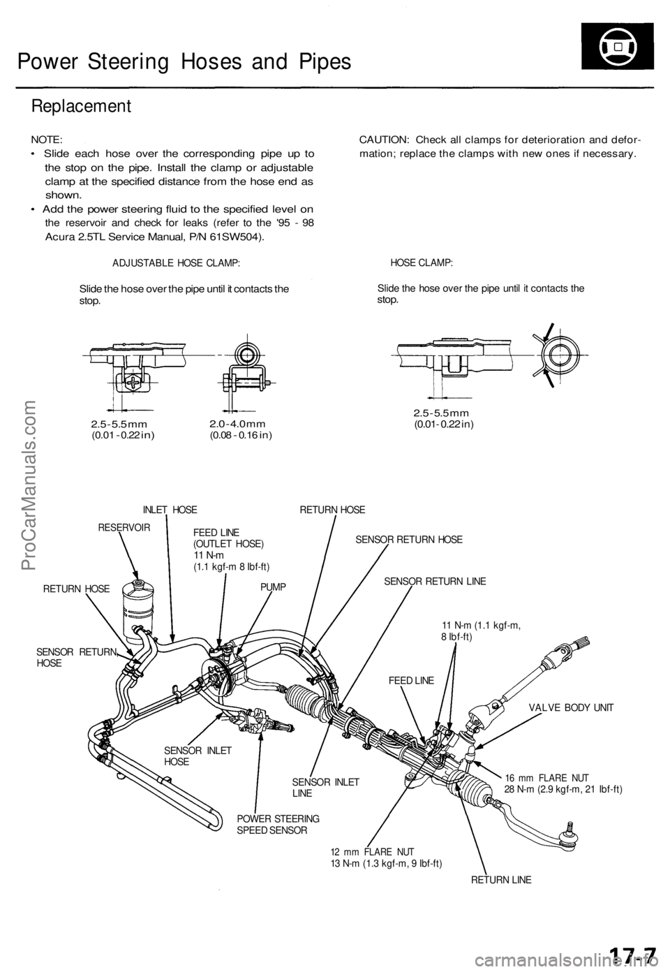
Power Steering Hoses and Pipes
Replacement
NOTE:
• Slide each hose over the corresponding pipe up to
the stop on the pipe. Install the clamp or adjustable
clamp at the specified distance from the hose end as
shown.
• Add the power steering fluid to the specified level on
the reservoir and check for leaks (refer to the '95 - 98
Acura 2.5TL Service Manual, P/N 61SW504).
CAUTION: Check all clamps for deterioration and defor-
mation; replace the clamps with new ones if necessary.
ADJUSTABLE HOSE CLAMP:
HOSE CLAMP:
Slide the hose over the pipe until it contacts the
stop.
Slide the hose over the pipe until it contacts the
stop.
2.5
-
5.5
mm
(0.01
-
0.22
in)
2.0
-
4.0
mm
(0.08
-
0.16
in)
2.5
-
5.5
mm
(0.01- 0.22 in)
INLET HOSE
RETURN HOSE
RESERVOIR
SENSOR RETURN HOSE
RETURN HOSE
SENSOR RETURN
HOSE
VALVE BODY UNIT
16 mm FLARE NUT
28 N-m (2.9 kgf-m, 21 Ibf-ft)
12 mm FLARE NUT
13 N-m (1.3 kgf-m, 9 Ibf-ft)
RETURN LINE
FEED LINE
(OUTLET HOSE)
11 N-m
(1.1 kgf-m 8 Ibf-ft)
PUMP
SENSOR INLET
HOSE
SENSOR INLET
LINE
POWER STEERING
SPEED SENSOR
FEED LINE
11 N-m (1.1 kgf-m,
8 Ibf-ft)
SENSOR RETURN LINEProCarManuals.com
Page 479 of 1771
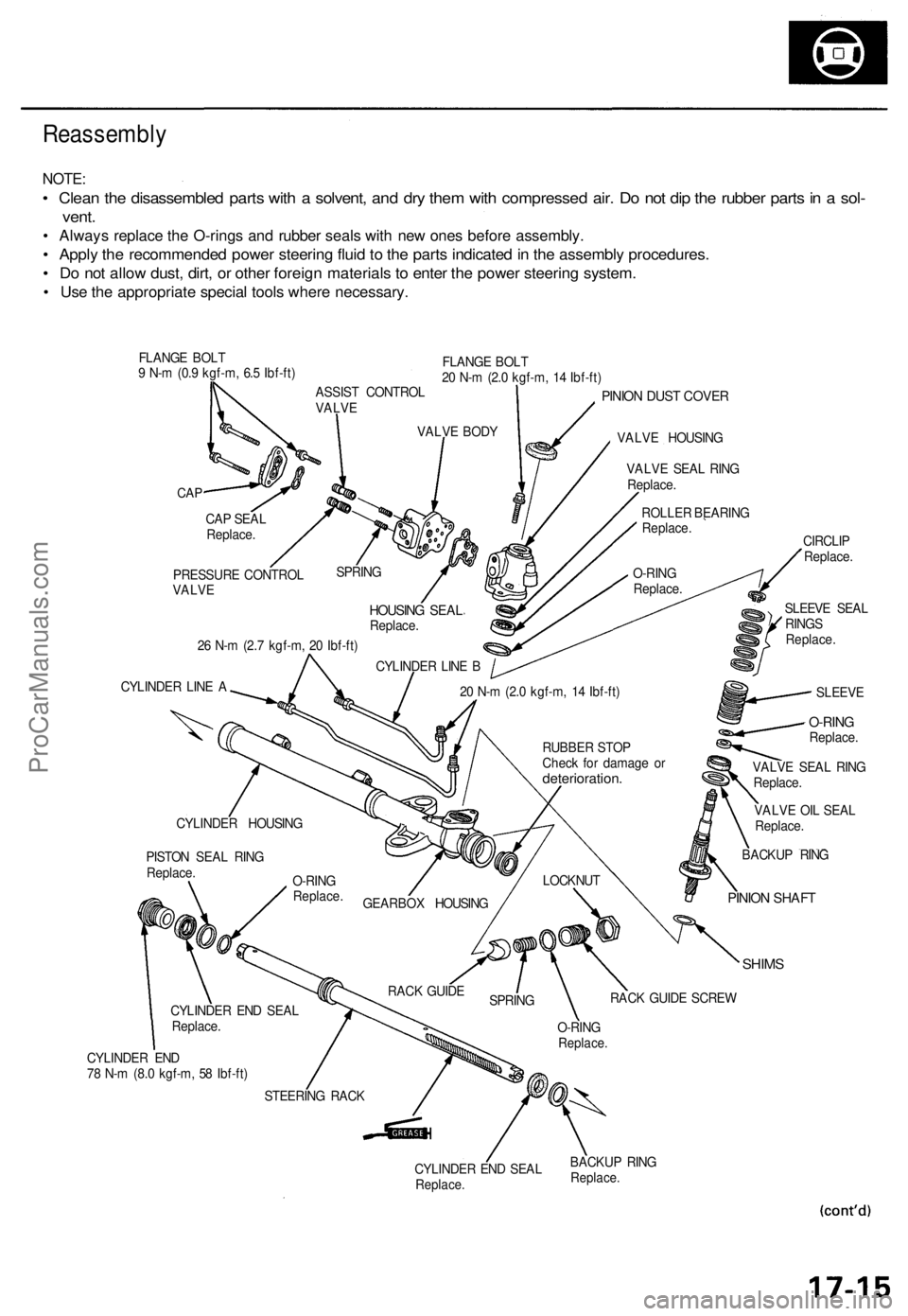
Reassembly
NOTE:
• Clean the disassembled parts with a solvent, and dry them with compressed air. Do not dip the rubber parts in a sol-
vent.
• Always replace the O-rings and rubber seals with new ones before assembly.
• Apply the recommended power steering fluid to the parts indicated in the assembly procedures.
• Do not allow dust, dirt, or other foreign materials to enter the power steering system.
• Use the appropriate special tools where necessary.
FLANGE BOLT
9 N-m (0.9 kgf-m, 6.5 Ibf-ft)
FLANGE BOLT
20 N-m (2.0 kgf-m, 14 Ibf-ft)
CAP
PINION DUST COVER
VALVE HOUSING
26 N-m (2.7 kgf-m, 20 Ibf-ft)
CYLINDER LINE A
VALVE OIL SEAL
Replace.
SHIMS
CYLINDER END
78 N-m (8.0 kgf-m, 58 Ibf-ft)
CYLINDER END SEAL
Replace.
BACKUP RING
Replace.
CAP SEAL
Replace.
PRESSURE CONTROL
VALVE
SPRING
HOUSING SEAL
Replace.
CYLINDER LINE B
VALVE BODY
ASSIST CONTROL
VALVE
VALVE SEAL RING
Replace.
ROLLER BEARING
Replace.
O-RING
Replace.
SLEEVE SEAL
RINGS
Replace.
CIRCLIP
Replace.
SLEEVE
20 N-m (2.0 kgf-m, 14 Ibf-ft)
BACKUP RING
PINION SHAFT
LOCKNUT
RACK GUIDE SCREW
O-RING
Replace.
SPRING
RACK GUIDE
STEERING RACK
CYLINDER END SEAL
Replace.
PISTON SEAL RING
Replace.
CYLINDER HOUSING
GEARBOX HOUSING
O-RING
Replace.
RUBBER STOP
Check for damage or
deterioration.
VALVE SEAL RING
Replace.
O-RING
Replace.ProCarManuals.com
Page 482 of 1771
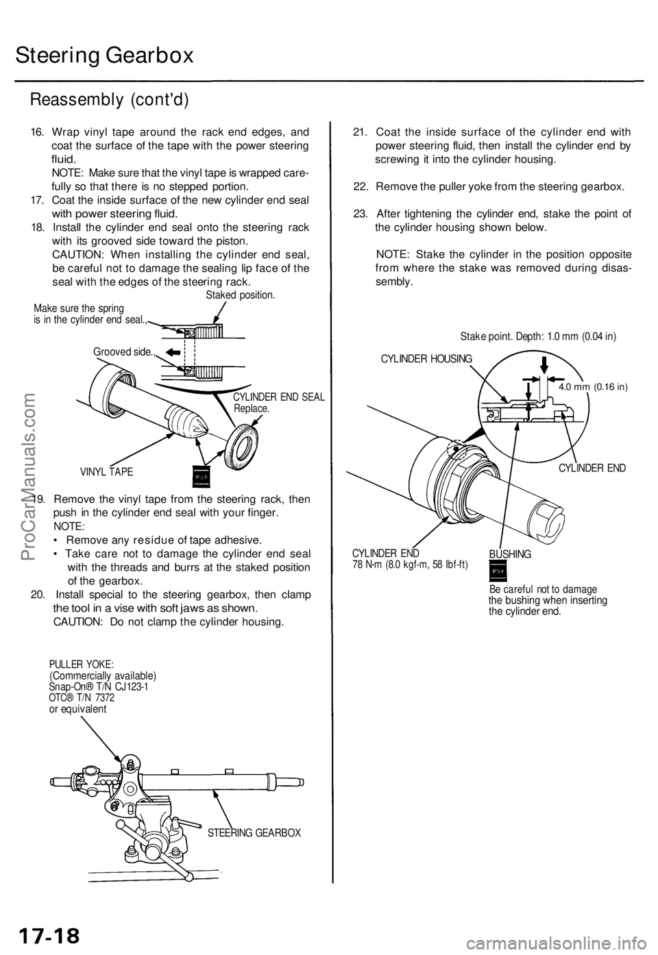
Steering Gearbox
Reassembly (cont'd)
CYLINDER END SEAL
Replace.
VINYL TAPE
19. Remove the vinyl tape from the steering rack, then
push in the cylinder end seal with your finger.
NOTE:
• Remove any residue of tape adhesive.
• Take care not to damage the cylinder end seal
with the threads and burrs at the staked position
of the gearbox.
20. Install special to the steering gearbox, then clamp
the tool in a vise with soft jaws as shown.
CAUTION: Do not clamp the cylinder housing.
PULLER YOKE:
(Commercially available)
Snap-On® T/N CJ123-1
OTC® T/N 7372
or equivalent
21. Coat the inside surface of the cylinder end with
power steering fluid, then install the cylinder end by
screwing it into the cylinder housing.
22. Remove the puller yoke from the steering gearbox.
23. After tightening the cylinder end, stake the point of
the cylinder housing shown below.
NOTE: Stake the cylinder in the position opposite
from where the stake was removed during disas-
sembly.
CYLINDER END
CYLINDER END
78 N-m (8.0 kgf-m, 58 Ibf-ft)
BUSHING
Be careful not to damage
the bushing when inserting
the cylinder end.
Grooved side.,
Stake point. Depth: 1.0 mm (0.04 in)
CYLINDER HOUSING
4.0 mm
(0.16
in)
STEERING GEARBOX
16. Wrap vinyl tape around the rack end edges, and
coat the surface of the tape with the power steering
fluid.
NOTE: Make sure that the vinyl tape is wrapped care-
fully so that there is no stepped portion.
17. Coat the inside surface of the new cylinder end seal
with power steering fluid.
18. Install the cylinder end seal onto the steering rack
with its grooved side toward the piston.
CAUTION: When installing the cylinder end seal,
be careful not to damage the sealing lip face of the
seal with the edges of the steering rack.
Staked position.
Make sure the spring
is in the cylinder end seal.,ProCarManuals.com