1995 ACURA TL bulb
[x] Cancel search: bulbPage 200 of 1771
PGM-FI System
System Description (cont'd)
3. Fuel Cut-off Control
During deceleration with the throttle valve closed, current to the fuel injectors is cut off to improve fuel economy at
speeds over 1,000 rpm.
Fuel cut-off action also takes place when engine speed exceeds 6,500 rpm, regardless of the position of the throttle
valve, to protect the engine from over-revving.
4. A/C Compressor Clutch Relay .
When the PCM receives a demand for cooling from the air conditioning system, it delays the compressor from being
energized, and enriches the mixture to assure a smooth transition to the A/C mode.
5. Evaporative Emission (EVAP) Purge Control Solenoid Valve
'96 model: When the engine coolant temperature is below 158°F (70°C), the PCM controls the EVAP purge control
solenoid valve which cuts vacuum to the EVAP purge control canister diaphragm.
'97 - 98 models: When the engine coolant temperature is above 99°F (37°C), the PCM controls the EVAP purge control
solenoid valve which controls vacuum to the EVAP purge control canister.
6. Intake Air Bypass (IAB) Low Control Solenoid Valve, Intake Air Bypass (IAB) High Control Solenoid Valve
When engine speed is below 3,350 rpm, the IAB High Control Solenoid Valve and IAB Low Control Solenoid Valve are
activated by a signal from the PCM. Intake air flows through a long chamber path, increasing torque at low RPM.
When engine speed is 3,350 - 3,950 rpm, the IAB Low Control Solenoid Valve is deactivated by the PCM. Intake air
flows through a short chamber path, increasing mid-range torque.
When the engine rpm is above 3,950 rpm, the IAB Low Control Solenoid Valve and IAB High Control Solenoid Valve are
deactivated by the PCM. This creates a very short intake path and increases high-speed torque.
7. Exhaust Gas Recirculation (EGR) Control Solenoid Valve
When the EGR is required for control of oxides of nitrogen (NOx) emissions, the PCM controls the EGR control solenoid
valve which supplies regulated vacuum to the EGR valve.
ECM Fail-safe/Back-up Functions
1. Fail-safe Function
When an abnormality occurs in a signal from a sensor, the PCM ignores that signal and assumes a pre-programmed
value for that sensor that allows the engine to continue to run.
2. Back-up Function
When an abnormality occurs in the PCM itself, the fuel injectors are controlled by a back-up circuit independent of the
system in order to permit minimal driving.
3. Self-diagnosis Function [Malfunction Indicator Lamp (MIL)]
When an abnormality occurs in a signal from a sensor, the PCM supplies ground for the MIL and stores the DTC in
erasable memory. When the ignition is initially turned on, the PCM supplies ground for the MIL for two seconds to
check the MIL bulb condition.
4. Two Driving Cycle Detection Method
To prevent false indications, the two driving cycle detection method is used for the H02S, fuel metering-related, idle
control system, ECT sensor, EGR system, TWC, EVAP control system and other self-diagnostic functions. When an
abnormality occurs, the PCM stores it in its memory. When the same abnormality recurs after the ignition switch is
turned OFF and ON (II) again, the PCM informs the driver by lighting the MIL.
However, to ease troubleshooting, this function is cancelled when you short the service check connector. The MIL will
then blink immediately when an abnormality occurs.ProCarManuals.com
Page 201 of 1771
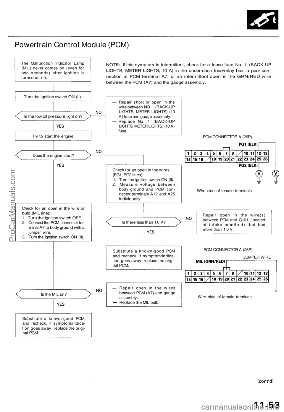
Powertrain Control Module (PCM)
NOTE: If this symptom is intermittent, check for a loose fuse No. 1 (BACK UP
LIGHTS, METER LIGHTS, 10 A) in the under-dash fuse/relay box, a poor con-
nection at PCM terminal A7, or an intermittent open in the GRN/RED wire
between the PCM (A7) and the gauge assembly.
Is the low oil pressure light on?
Try to start the engine.
Does the engine start?
Check for an open in the wire or
bulb (MIL line):
1. Turn the ignition switch OFF.
2. Connect the PCM connector ter-
minal A7 to body ground with a
jumper wire.
3. Turn the ignition switch ON (II).
Is the MIL on?
Substitute a known-good PCM,
and recheck. If symptom/indica-
tion goes away, replace the origi-
nal
PCM.
— Repair short or open in the
wire between NO. 1 (BACK-UP
LIGHTS, METER LIGHTS) (10
A) fuse and gauge assembly.
— Replace No. 1 (BACK-UP
LIGHTS, METER LIGHTS) (10 A)
fuse.
PCM CONNECTOR A (26P)
Check for an open in the wires
(PG1, PG2 lines):
1. Turn the ignition switch ON (II).
2. Measure voltage between
body ground and PCM con-
nector terminals A12 and A25
individually.
Wire side of female terminals
Is there less than 1.0 V?
Repair open in the wire(s)
between PCM and G101 (located
at intake manifold) that had
more than 1.0 V.
PCM CONNECTOR A (26P)
JUMPER WIRE
Wire side of female terminals
Repair open in the wires
between PCM (A7) and gauge
assembly.
Replace the MIL bulb.
Substitute a known-good PCM
and recheck. If symptom/indica-
tion goes away, replace the origi-
nal
PCM.
Turn the ignition switch ON (II).
The Malfunction Indicator Lamp
(MIL) never comes on (even for
two seconds) after ignition is
turned on (II).ProCarManuals.com
Page 511 of 1771
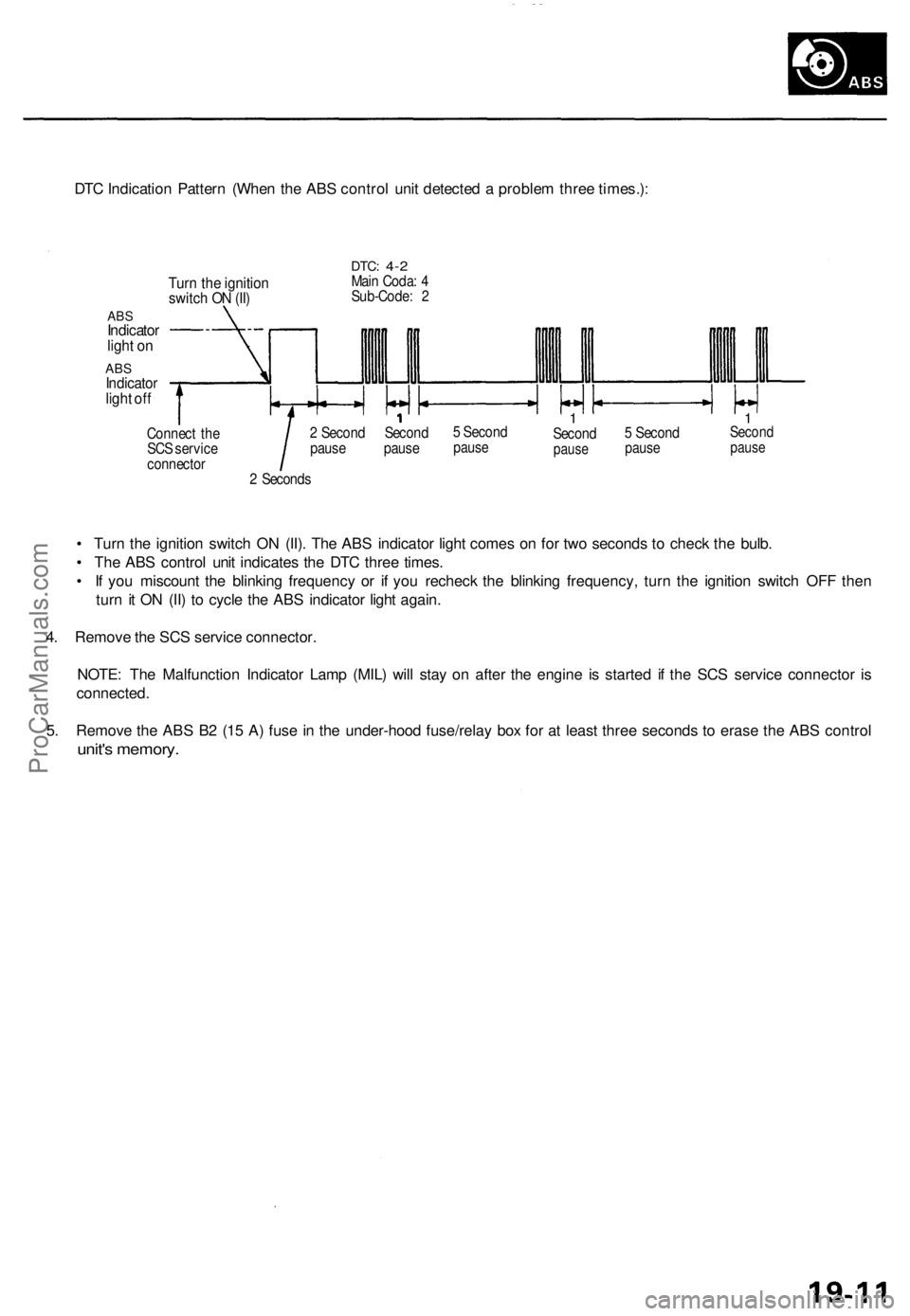
DTC Indication Pattern (When the ABS control unit detected a problem three times.):
Turn the ignition
switch ON (II)
ABS
Indicator
light on
ABS
Indicator
light off
DTC:
4-2
Main Coda: 4
Sub-Code: 2
Connect the
SCS service
connector
2 Second Second
pause pause
5 Second
pause
1
Second
pause
5 Second
pause
1
Second
pause
2 Seconds
• Turn the ignition switch ON (II). The ABS indicator light comes on for two seconds to check the bulb.
• The ABS control unit indicates the DTC three times.
• If you miscount the blinking frequency or if you recheck the blinking frequency, turn the ignition switch OFF then
turn it ON (II) to cycle the ABS indicator light again.
4. Remove the SCS service connector.
NOTE: The Malfunction Indicator Lamp (MIL) will stay on after the engine is started if the SCS service connector is
connected.
5. Remove the ABS B2 (15 A) fuse in the under-hood fuse/relay box for at least three seconds to erase the ABS control
unit's memory.ProCarManuals.com
Page 524 of 1771
Diagnostic Troubl e Cod e (DTC )
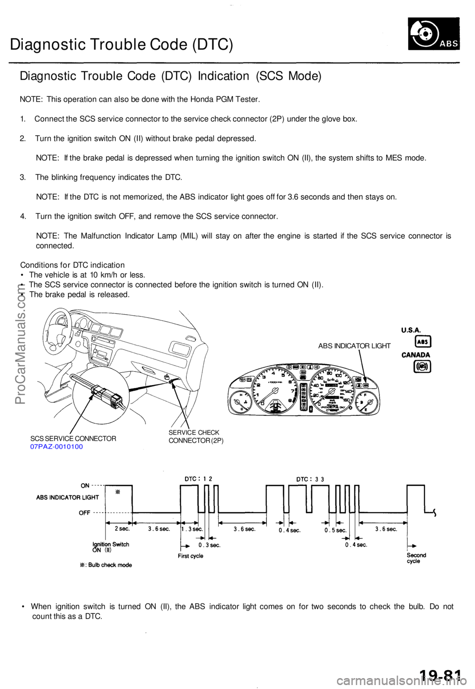
Diagnosti c Troubl e Cod e (DTC ) Indicatio n (SC S Mode )
NOTE: Thi s operatio n ca n als o b e don e wit h th e Hond a PG M Tester .
1 . Connec t th e SC S servic e connecto r t o th e servic e chec k connecto r (2P ) unde r th e glov e box .
2 . Tur n th e ignitio n switc h O N (II ) withou t brak e peda l depressed .
NOTE : I f th e brak e peda l i s depresse d whe n turnin g th e ignitio n switc h O N (II) , th e syste m shift s t o ME S mode .
3 . Th e blinkin g frequenc y indicate s th e DTC .
NOTE : I f th e DT C is no t memorized , th e AB S indicato r ligh t goe s of f fo r 3. 6 second s an d the n stay s on .
4 . Tur n th e ignitio n switc h OFF , an d remov e th e SC S servic e connector .
NOTE : Th e Malfunctio n Indicato r Lam p (MIL ) wil l sta y o n afte r th e engin e i s starte d i f th e SC S servic e connecto r i s
connected .
Condition s fo r DT C indicatio n
• Th e vehicl e is a t 1 0 km/ h o r less .
• Th e SC S servic e connecto r i s connecte d befor e th e ignitio n switc h i s turne d O N (II) .
• Th e brak e peda l i s released .
SCS SERVIC E CONNECTO R07PAZ-001010 0
SERVICE CHEC KCONNECTO R (2P )
ABS INDICATO R LIGH T
• Whe n ignitio n switc h i s turne d O N (II) , th e AB S indicato r ligh t come s o n fo r tw o second s t o chec k th e bulb . D o no t
coun t thi s a s a DTC .
ProCarManuals.com
Page 536 of 1771
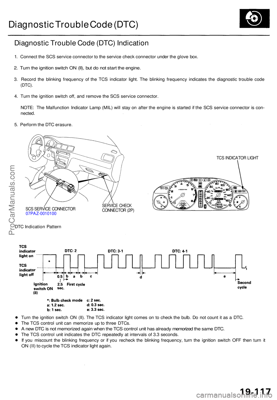
Diagnostic Troubl e Cod e (DTC )
Diagnosti c Troubl e Cod e (DTC ) Indicatio n
1. Connec t th e SC S servic e connecto r t o th e servic e chec k connecto r unde r th e glov e box .
2. Tur n th e ignitio n switc h O N (II) , bu t d o no t star t th e engine .
3. Recor d th e blinkin g frequenc y o f th e TC S indicato r light . Th e blinkin g frequenc y indicate s th e diagnosti c troubl e cod e
(DTC) .
4. Tur n th e ignitio n switc h off , an d remov e th e SC S servic e connector .
NOTE : Th e Malfunctio n Indicato r Lam p (MIL ) wil l sta y o n afte r th e engin e is starte d i f th e SC S servic e connecto r i s con -
nected .
5 . Perfor m th e DT C erasure .
SCS SERVIC E CONNECTO R07PAZ-001010 0
TCS INDICATO R LIGH T
SERVIC E CHEC KCONNECTO R (2P )
DTC Indicatio n Patter n
Tur n th e ignitio n switc h O N (II) . Th e TC S indicato r ligh t come s o n t o chec k th e bulb . D o no t coun t i t a s a DTC .
Th e TC S contro l uni t ca n memoriz e u p to thre e DTCs .
A ne w DT C is no t memorize d agai n whe n th e TC S contro l uni t ha s alread y memorize d th e sam e DTC .
The TC S contro l uni t indicate s th e DT C repeatedl y a t interval s o f 3. 3 seconds .
I f yo u miscoun t th e blinkin g frequenc y o r i f yo u rechec k th e blinkin g frequency , tur n th e ignitio n switc h OF F the n tur n i t
O N (II ) t o cycl e th e TC S indicato r ligh t again .
ProCarManuals.com
Page 601 of 1771
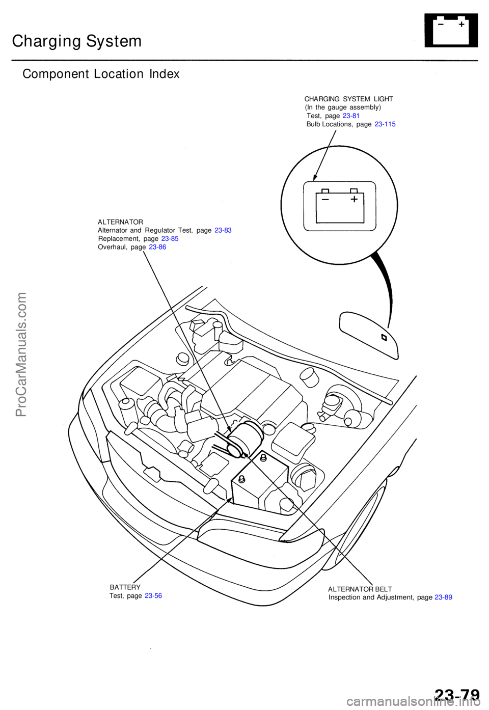
Charging Syste m
Componen t Locatio n Inde x
CHARGIN G SYSTE M LIGH T
(I n th e gaug e assembly )
ALTERNATO RAlternator an d Regulato r Test , pag e 23-8 3
Replacement , pag e 23-8 5
Overhaul , pag e 23-8 6
ALTERNATOR BEL T
Inspectio n an d Adjustment , pag e 23-8 9
BATTER YTest, pag e 23-5 6 Test
, pag e 23-8 1
Bulb Locations , pag e 23- 115
ProCarManuals.com
Page 612 of 1771
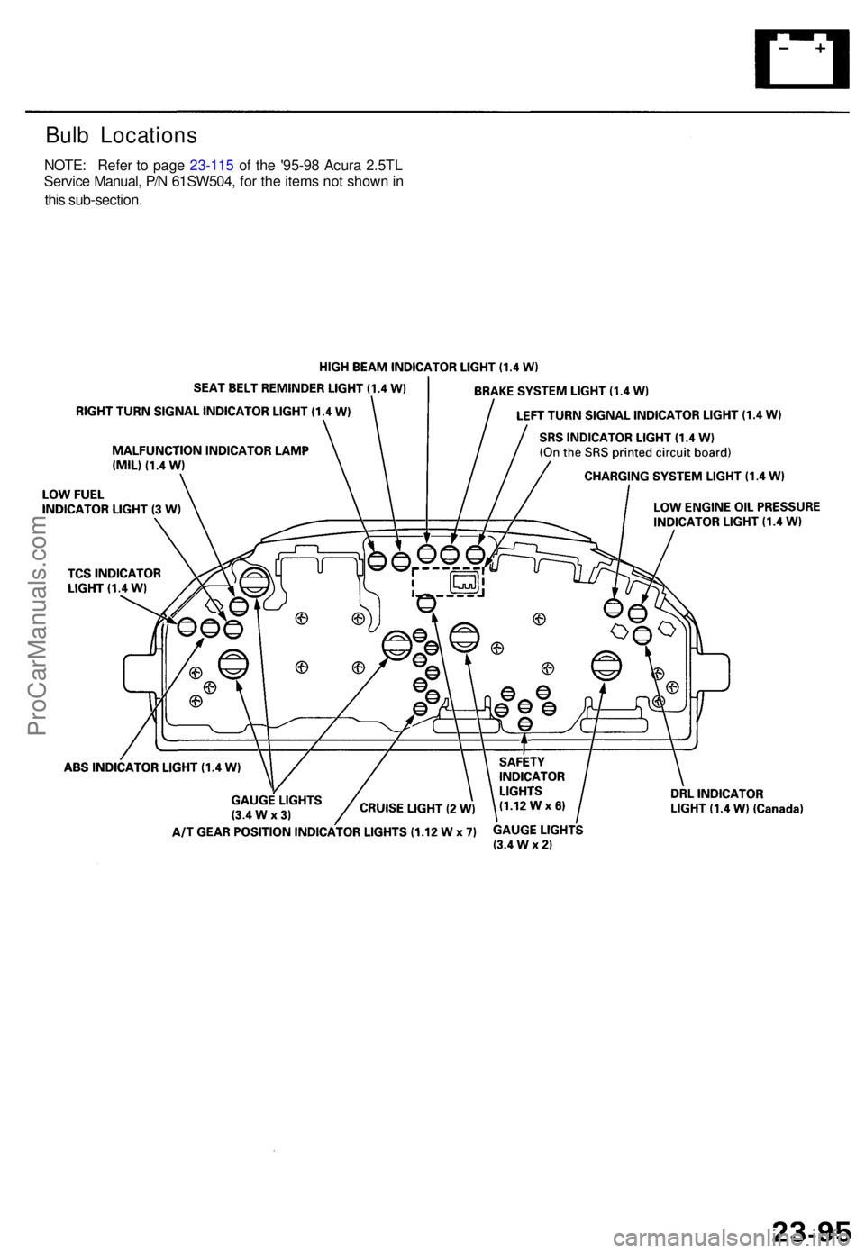
Bulb Location s
NOTE: Refer to page 23-115 of the '95-98 Acura 2.5TL
Servic e Manual , P/ N 61SW504 , for the items not shown in
thi s sub-section .
ProCarManuals.com
Page 615 of 1771
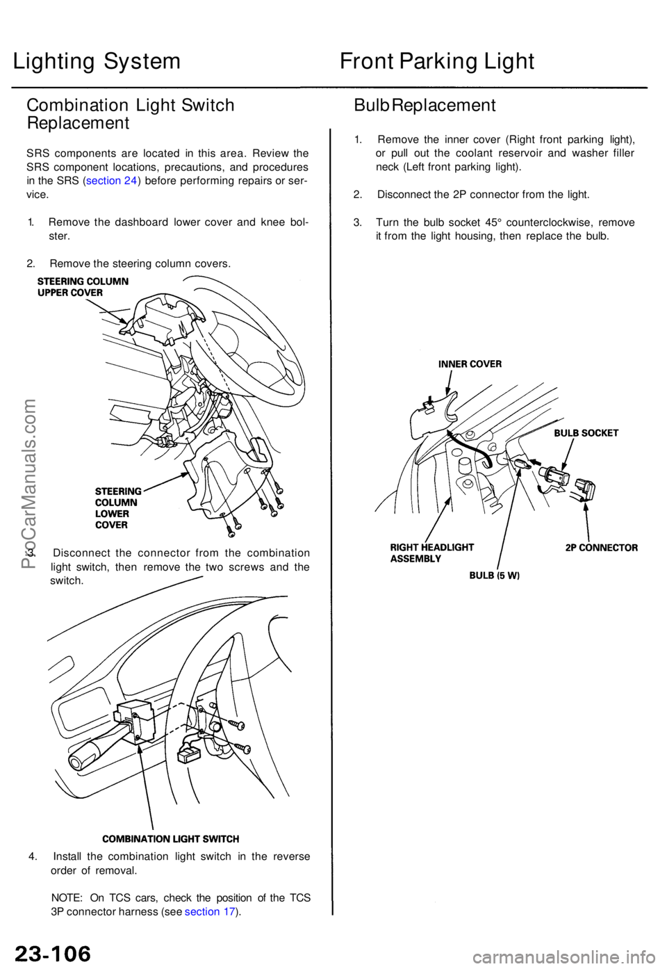
4. Instal l th e combinatio n ligh t switc h i n th e revers e
orde r o f removal .
NOTE : O n TC S cars , chec k th e positio n o f th e TC S
3 P connecto r harnes s (se e sectio n 17 ).
Lightin g Syste m
Combinatio n Ligh t Switc h
Replacemen t
SRS component s ar e locate d i n thi s area . Revie w th e
SR S componen t locations , precautions , an d procedure s
i n th e SR S (sectio n 24 ) befor e performin g repair s o r ser -
vice .
1 . Remov e th e dashboar d lowe r cove r an d kne e bol -
ster .
2 . Remov e th e steerin g colum n covers .
3 . Disconnec t th e connecto r fro m th e combinatio n
ligh t switch , the n remov e th e tw o screw s an d th e
switch .
Front Parkin g Ligh t
Bulb Replacemen t
1. Remov e th e inne r cove r (Righ t fron t parkin g light) ,
o r pul l ou t th e coolan t reservoi r an d washe r fille r
nec k (Lef t fron t parkin g light) .
2 . Disconnec t th e 2 P connecto r fro m th e light .
3 . Tur n th e bul b socke t 45 ° counterclockwise , remov e
i t fro m th e ligh t housing , the n replac e th e bulb .
ProCarManuals.com