1995 ACURA TL oil type
[x] Cancel search: oil typePage 28 of 1771

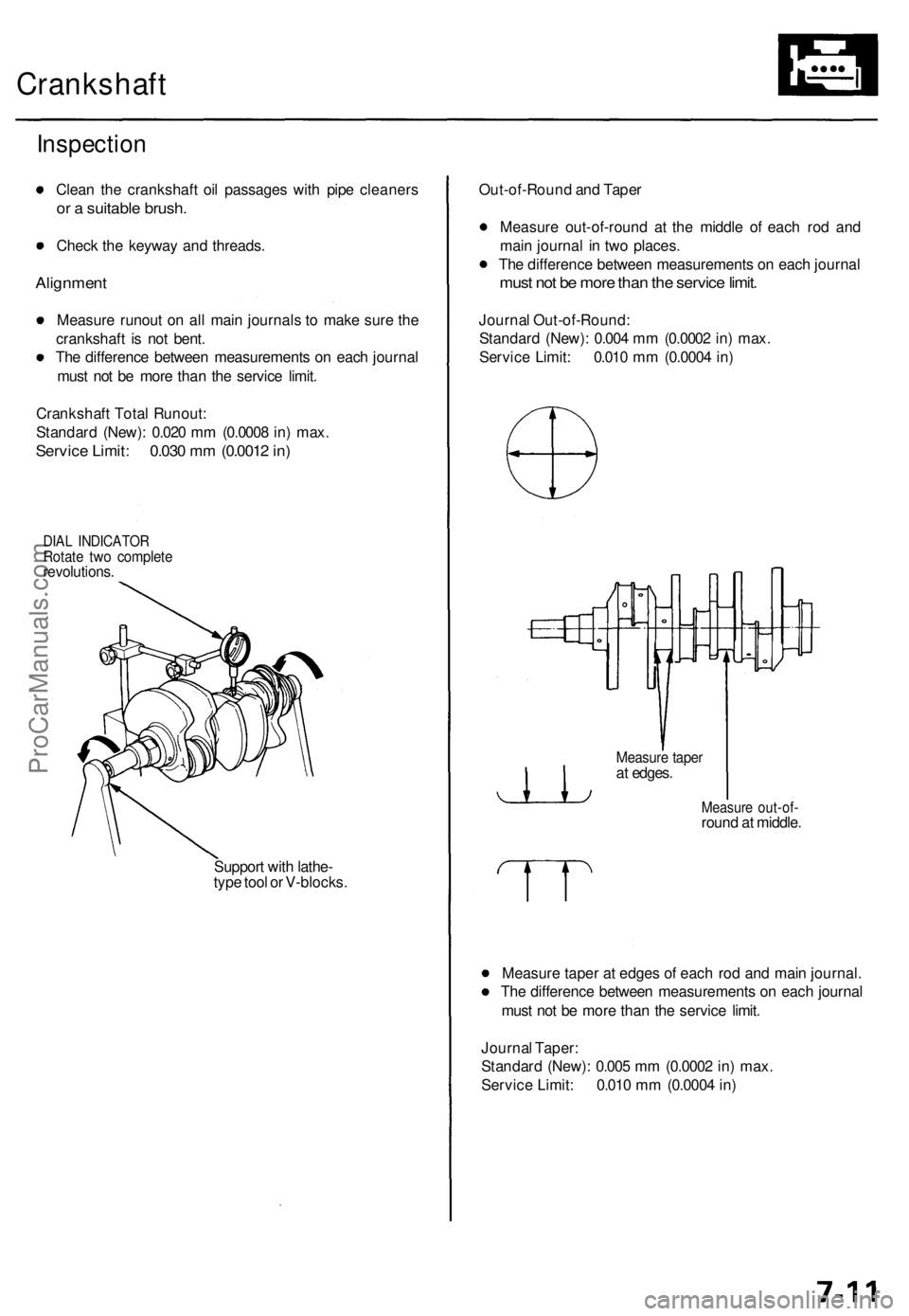
Lubrication Points
For the details of lubrication points and types of lubricants to be applied, refer to the illustrated index and various work
procedures (such as Assembly/Reassembly, Replacement, Overhaul, Installation, etc.) contained in each section.
No.
1
2
3
4
5
6
7
8
9
10
11
12
13
14
15
16
17
18
19
20
21
LUBRICATION POINTS
Engine
Transmission
Brake Line (Includes Anti-lock brake line)
Power steering gearbox
Steering boots
Throttle cable end
Steering ball joints
Shift lever (Automatic transmission)
Pedal linkage
Intermediate shaft
Brake master cylinder pushrod
Fuel
fill
lid
Trunk hinges
Door hinges upper and lower
Door opening detents
Hood hinges and hood latch
Brake pipe joint (Front and rear wheel house)
Caliper Piston seal, Dust seal,
Caliper pin, Piston
Power steering system
Differential
A/C compressor
LUBRICANT
API Service Grade: Use SH "Energy Conserving II" or SJ
"Energy Conserving" grade oil.
The oil container may also display the API Certification
mark shown below. Make sure it says "For Gasoline
Engines."
SAE Viscosity: See chart below.
Genuine Honda Premium Formula Automatic
Transmission Fluid (ATF)*1
Genuine Honda DOT3 Brake Fluid*2
Steering grease P/N 08733 - B070E
Multi-purpose grease
Honda White Lithium Grease
Rust preventives
Silicone grease
Genuine Honda Power Steering Fluid-V or S*3
Hypoid gear Oil API service GL4 or GL5
Viscosity:
at above -18°C (0°F): SAE 90
at less than -18°C (0°F): SAE 80 W-90
Compressor oil:
DENSO: ND-OIL8 (P/N 38897 - PR7 - A01 AH or 38899 -
PR7-A01)
(For Refrigerant: HFC-134a (R-134a))
API SERVICE LABEL
API CERTIFICATION MARK
Recommended Engine Oil
Engine oil viscosity for ambient temperature ranges
NOTE: The following information as marked *1, *2 and *3 on above chart details for 1997 model:
*1: Always use Genuine Honda Premium Formula Automatic Transmission Fluid (ATF). Using a non-Honda ATF can affect
shift quality.
*2: Always use Genuine Honda DOT3 Brake Fluid. Using a non-Honda brake fluid can cause corrosion and decrease the
life of the system.
*3: Always use Genuine Honda Power Steering Fluid-V or S. Using any other type of power steering fluid or automatic
transmission fluid can cause increase wear and poor steering in cold weather.ProCarManuals.com
Page 108 of 1771

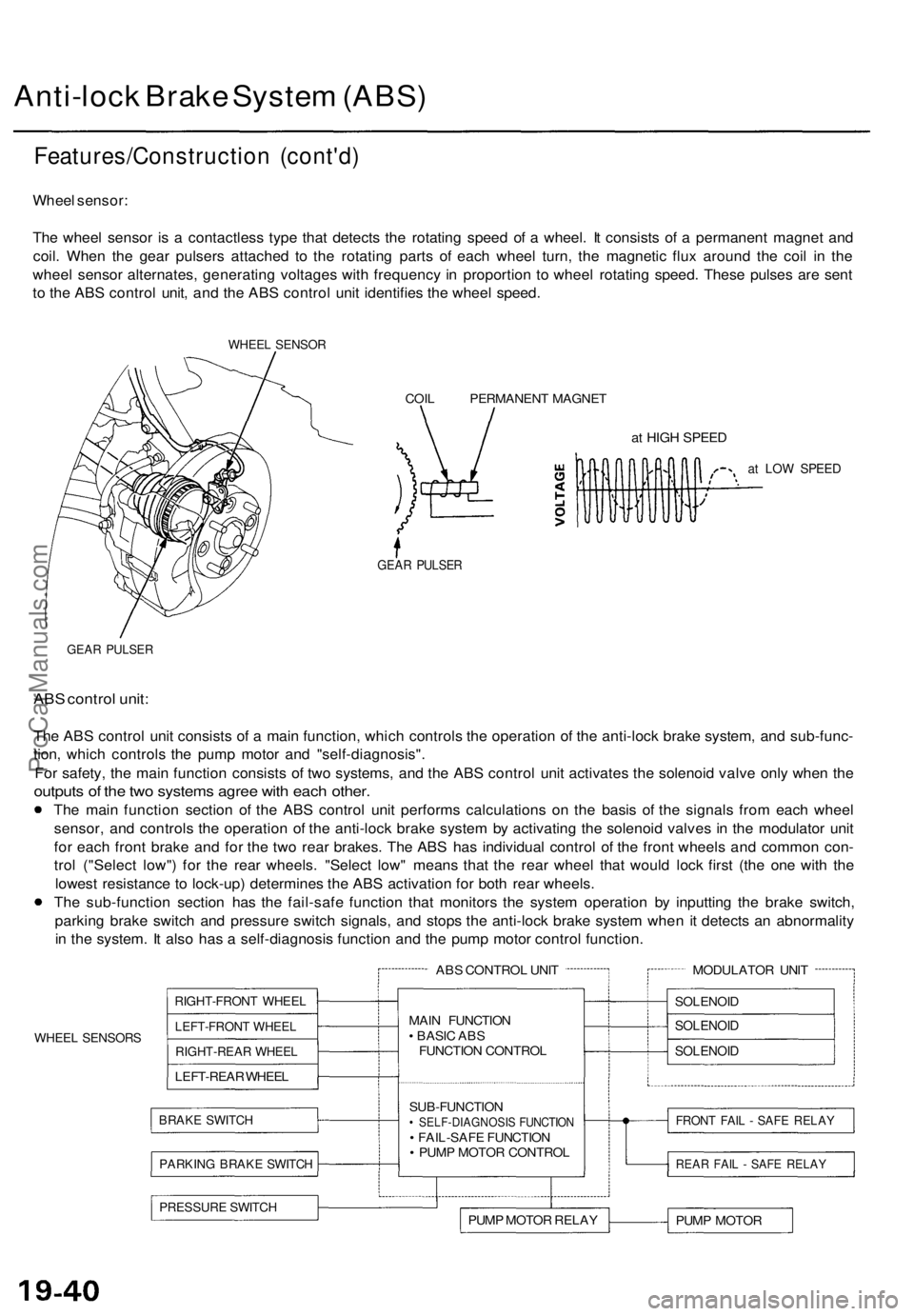
Crankshaft
Inspection
Clean the crankshaft oil passages with pipe cleaners
or a suitable brush.
Check the keyway and threads.
Alignment
Measure runout on all main journals to make sure the
crankshaft is not bent.
The difference between measurements on each journal
must not be more than the service limit.
Crankshaft Total Runout:
Standard (New): 0.020 mm (0.0008 in) max.
Service Limit: 0.030 mm (0.0012 in)
DIAL INDICATOR
Rotate two complete
revolutions.
Support with lathe-
type tool or V-blocks.
Out-of-Round and Taper
Measure out-of-round at the middle of each rod and
main journal in two places.
The difference between measurements on each journal
must not be more than the service limit.
Journal Out-of-Round:
Standard (New): 0.004 mm (0.0002 in) max.
Service Limit: 0.010 mm (0.0004 in)
Measure out-of-
round at middle.
Measure taper at edges of each rod and main journal.
The difference between measurements on each journal
must not be more than the service limit.
Journal Taper:
Standard (New): 0.005 mm (0.0002 in) max.
Service Limit: 0.010 mm (0.0004 in)
Measure taper
at edges.ProCarManuals.com
Page 1290 of 1771

Anti-lock Brake System (ABS)
Features/Construction (cont'd)
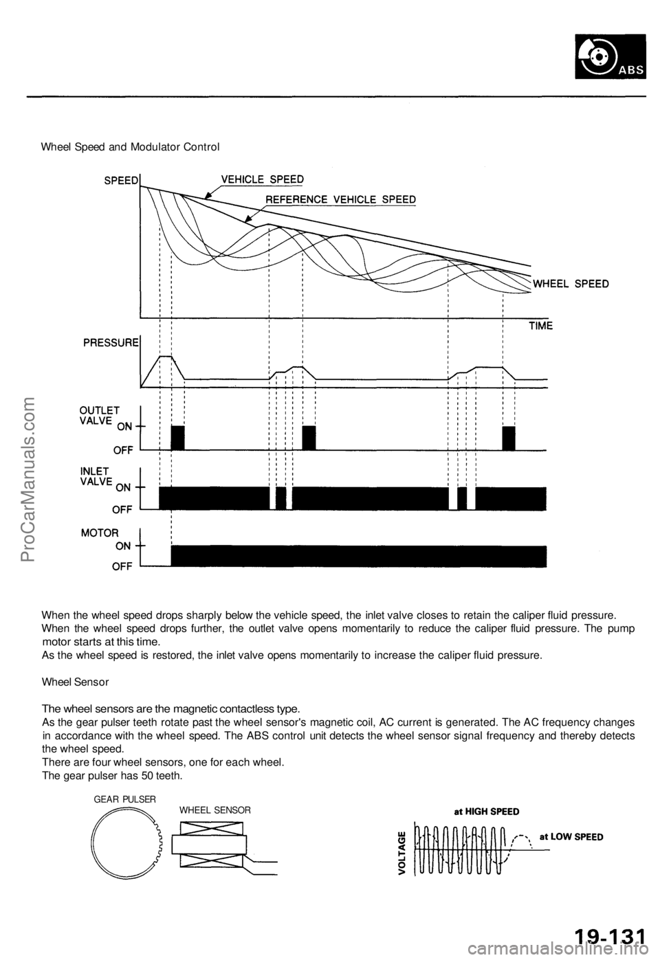
Wheel sensor:
The wheel sensor is a contactless type that detects the rotating speed of a wheel. It consists of a permanent magnet and
coil. When the gear pulsers attached to the rotating parts of each wheel turn, the magnetic flux around the coil in the
wheel sensor alternates, generating voltages with frequency in proportion to wheel rotating speed. These pulses are sent
to the ABS control unit, and the ABS control unit identifies the wheel speed.
WHEEL SENSOR
COIL PERMANENT MAGNET
at HIGH SPEED
at LOW SPEED
GEAR PULSER
GEAR PULSER
ABS control unit:
The ABS control unit consists of a main function, which controls the operation of the anti-lock brake system, and sub-func-
tion, which controls the pump motor and "self-diagnosis".
For safety, the main function consists of two systems, and the ABS control unit activates the solenoid valve only when the
outputs of the two systems agree with each other.
The main function section of the ABS control unit performs calculations on the basis of the signals from each wheel
sensor, and controls the operation of the anti-lock brake system by activating the solenoid valves in the modulator unit
for each front brake and for the two rear brakes. The ABS has individual control of the front wheels and common con-
trol ("Select low") for the rear wheels. "Select low" means that the rear wheel that would lock first (the one with the
lowest resistance to lock-up) determines the ABS activation for both rear wheels.
The sub-function section has the fail-safe function that monitors the system operation by inputting the brake switch,
parking brake switch and pressure switch signals, and stops the anti-lock brake system when it detects an abnormality
in the system. It also has a self-diagnosis function and the pump motor control function.
WHEEL SENSORS
ABS CONTROL UNIT
RIGHT-FRONT WHEEL
LEFT-FRONT WHEEL
RIGHT-REAR WHEEL
LEFT-REAR WHEEL
BRAKE SWITCH
PARKING BRAKE SWITCH
MAIN FUNCTION
• BASIC ABS
FUNCTION CONTROL
SUB-FUNCTION
• SELF-DIAGNOSIS FUNCTION
• FAIL-SAFE FUNCTION
• PUMP MOTOR CONTROL
PRESSURE SWITCH
PUMP MOTOR RELAY
MODULATOR UNIT
SOLENOID
SOLENOID
SOLENOID
FRONT FAIL - SAFE RELAY
REAR FAIL - SAFE RELAY
PUMP MOTORProCarManuals.com
Page 1326 of 1771

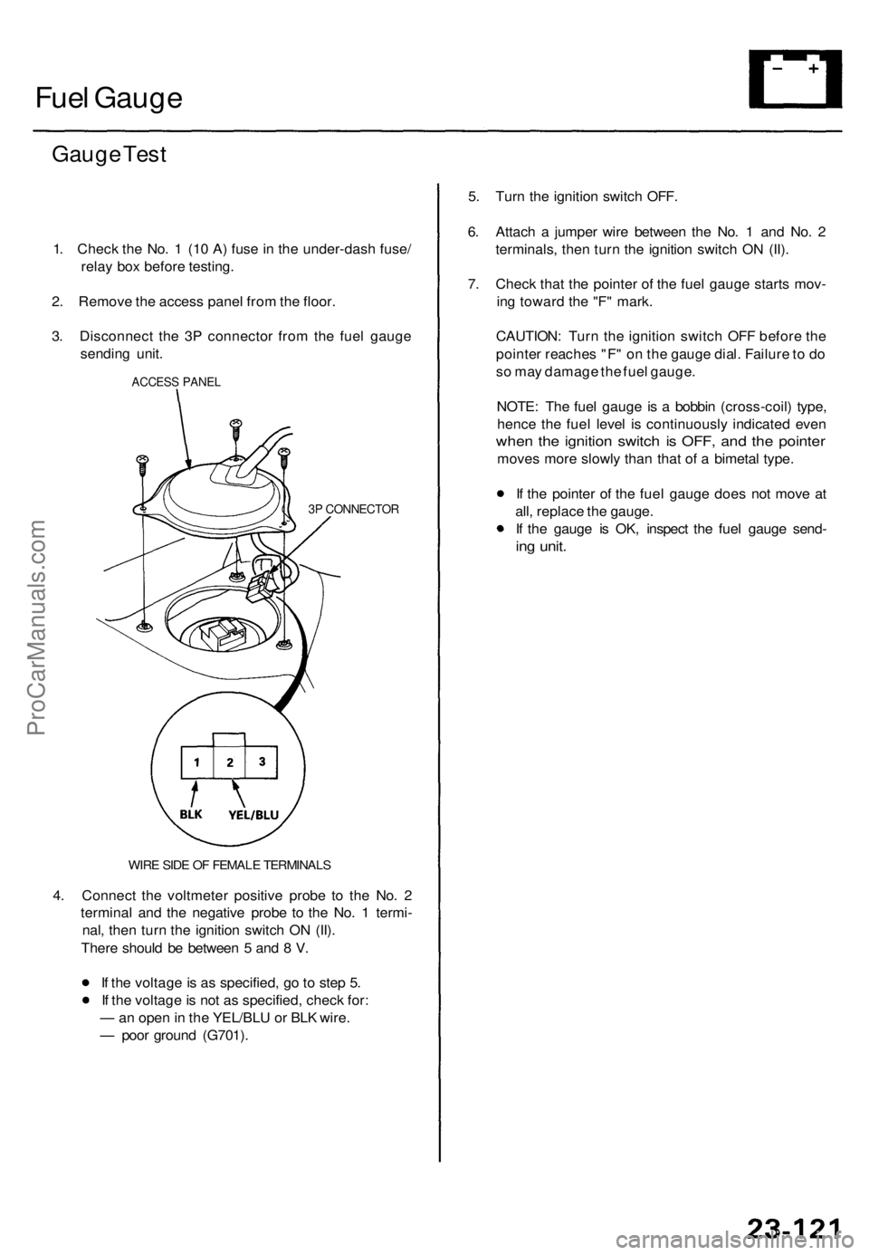
Wheel Speed and Modulator Control
When the wheel speed drops sharply below the vehicle speed, the inlet valve closes to retain the caliper fluid pressure.
When the wheel speed drops further, the outlet valve opens momentarily to reduce the caliper fluid pressure. The pump
motor starts at this time.
As the wheel speed is restored, the inlet valve opens momentarily to increase the caliper fluid pressure.
Wheel Sensor
The wheel sensors are the magnetic contactless type.
As the gear pulser teeth rotate past the wheel sensor's magnetic coil, AC current is generated. The AC frequency changes
in accordance with the wheel speed. The ABS control unit detects the wheel sensor signal frequency and thereby detects
the wheel speed.
There are four wheel sensors, one for each wheel.
The gear pulser has 50 teeth.
GEAR PULSER
WHEEL SENSORProCarManuals.com
Page 1601 of 1771

Fuel Gaug e
Gauge Tes t
1. Chec k th e No . 1 (1 0 A ) fus e in th e under-das h fuse /
rela y bo x befor e testing .
2 . Remov e th e acces s pane l fro m th e floor .
3 . Disconnec t th e 3 P connecto r fro m th e fue l gaug e
sendin g unit .
ACCES S PANE L
3P CONNECTO R
WIRE SID E O F FEMAL E TERMINAL S
4. Connec t th e voltmete r positiv e prob e t o th e No . 2
termina l an d th e negativ e prob e t o th e No . 1 termi -
nal , the n tur n th e ignitio n switc h O N (II) .
Ther e shoul d b e betwee n 5 an d 8 V .
I f th e voltag e is a s specified , g o to ste p 5 .
I f th e voltag e is no t a s specified , chec k for :
— an ope n in th e YEL/BL U o r BL K wire .
— poo r groun d (G701) . 5
. Tur n th e ignitio n switc h OFF .
6 . Attac h a jumpe r wir e betwee n th e No . 1 an d No . 2
terminals , the n tur n th e ignitio n switc h O N (II) .
7 . Chec k tha t th e pointe r o f th e fue l gaug e start s mov -
in g towar d th e "F " mark .
CAUTION : Tur n th e ignitio n switc h OF F befor e th e
pointe r reache s "F " o n th e gaug e dial . Failur e to d o
s o ma y damag e th e fue l gauge .
NOTE : Th e fue l gaug e is a bobbi n (cross-coil ) type ,
henc e th e fue l leve l i s continuousl y indicate d eve n
when th e ignitio n switc h i s OFF , an d th e pointe r
moves mor e slowl y tha n tha t o f a bimeta l type .
I f th e pointe r o f th e fue l gaug e doe s no t mov e a t
all , replac e th e gauge .
I f th e gaug e i s OK , inspec t th e fue l gaug e send -
ing unit .
ProCarManuals.com