1995 ACURA TL ESP
[x] Cancel search: ESPPage 107 of 1771
Pistons and Crankshaft
Removal (cont'd)
5. Remove the bearing from the cap. Keep all caps/bear-
ings in order.
6. Remove the upper bearing halves from the connect-
ing rods and set them aside with their respective caps.
7. Reinstall the cap on the rod after removing each
piston/connecting rod assembly.
8. To avoid mixup on reassembly, mark each piston/con-
necting rod assembly with its cylinder number.
NOTE: The existing number on the connecting rod
does not indicate its position in the engine, it indicates
the rod bore size.
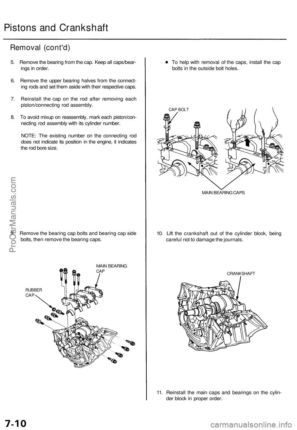
9. Remove the bearing cap bolts and bearing cap side
bolts, then remove the bearing caps.
MAIN BEARING
CAP
RUBBER
CAP
To help with removal of the caps, install the cap
bolts in the outside bolt holes.
CAP BOLT
MAIN BEARING CAPS
10. Lift the crankshaft out of the cylinder block, being
careful not to damage the journals.
CRANKSHAFT
11. Reinstall the main caps and bearings on the cylin-
der block in proper order.ProCarManuals.com
Page 193 of 1771
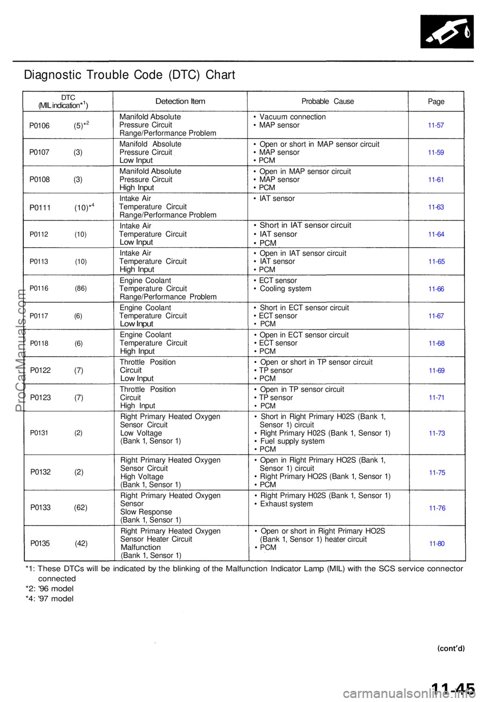
Diagnostic Troubl e Cod e (DTC ) Char t
DTC(MIL indication*1)
P010 6 (5)*2
P010 7 (3 )
P010 8 (3 )
P0111 (10)*4
P011 2 (10 )
P011 3 (10 )
P011 6 (86 )
P011 7
(6 )
P0118 (6 )
P0122 (7 )
P012 3 (7 )
P0131 (2 )
P0132 (2 )
P013 3 (62 )
P013 5 (42 )
Detection Ite m
Manifol d Absolut ePressure Circui t
Range/Performanc e Proble m
Manifol d Absolut e
Pressur e Circui t
Low Inpu t
Manifol d Absolut ePressure Circui tHigh Inpu t
Intake Ai r
Temperatur e Circui t
Range/Performanc e Proble m
Intak e Ai r
Temperatur e Circui t
Low Inpu t
Intak e Ai r
Temperatur e Circui t
High Inpu t
Engin e Coolan t
Temperatur e Circui t
Range/Performanc e Proble m
Engin e Coolan t
Temperatur e Circui t
Low Inpu t
Engin e Coolan t
Temperatur e Circui t
High Inpu t
Throttl e Positio nCircuitLow Inpu t
Throttl e Positio n
Circui t
Hig h Inpu t
Righ t Primar y Heate d Oxyge n
Senso r Circui t
Lo w Voltag e
(Ban k 1 , Senso r 1 )
Righ t Primar y Heate d Oxyge n
Senso r Circui t
Hig h Voltag e
(Ban k 1 , Senso r 1 )
Righ t Primar y Heate d Oxyge n
SensorSlow Respons e
(Ban k 1 , Senso r 1 )
Righ t Primar y Heate d Oxyge n
Senso r Heate r Circui t
Malfunctio n(Bank 1 , Senso r 1 ) Probabl
e Caus e
• Vacuu m connectio n
• MA P senso r
• Ope n o r shor t i n MA P senso r circui t
• MA P senso r
• PC M
• Ope n i n MA P senso r circui t
• MA P senso r
• PC M
• IA T senso r
• Shor t i n IA T senso r circui t• IA T senso r
• PC M
• Ope n i n IA T senso r circui t
• IA T senso r
• PC M
• EC T senso r
• Coolin g syste m
• Shor t i n EC T senso r circui t
• EC T senso r
• PC M
• Ope n in EC T senso r circui t
• EC T senso r
• PC M
• Ope n o r shor t i n T P senso r circui t
• T P senso r
• PC M
• Ope n i n T P senso r circui t
• T P senso r
• PC M
• Shor t i n Righ t Primar y H02 S (Ban k 1 ,
Senso r 1 ) circui t
• Righ t Primar y H02 S (Ban k 1 , Senso r 1 )
• Fue l suppl y syste m
• PC M
• Ope n i n Righ t Primar y HO2 S (Ban k 1 ,
Senso r 1 ) circui t
• Righ t Primar y HO2 S (Ban k 1 , Senso r 1 )
• PC M
• Righ t Primar y H02 S (Ban k 1 , Senso r 1 )
• Exhaus t syste m
• Ope n o r shor t i n Righ t Primar y HO2 S
(Ban k 1 , Senso r 1 ) heate r circui t
• PC M
Page
11-5 7
11-5 9
11-6 1
11-6 3
11-6 4
11-6 5
11-6 6
11-6 7
11-6 8
11-6 9
11-7 1
11-7 3
11-7 5
11-7 6
11-8 0
*1: Thes e DTC s wil l b e indicate d b y th e blinkin g o f th e Malfunctio n Indicato r Lam p (MIL ) wit h th e SC S servic e connecto r
connected
*2: '9 6 mode l
*4: '9 7 mode l
ProCarManuals.com
Page 194 of 1771
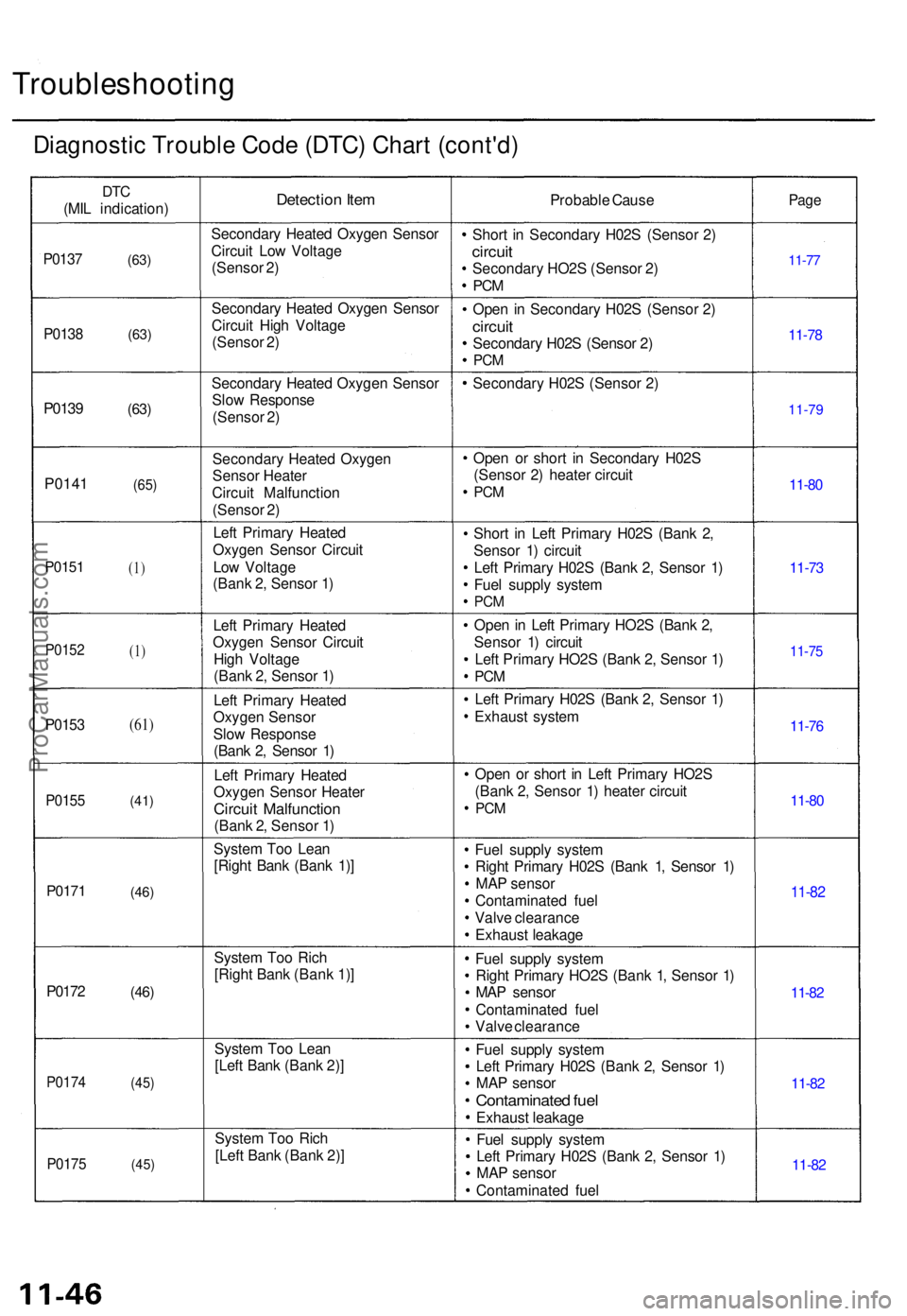
Troubleshooting
Diagnostic Troubl e Cod e (DTC ) Char t (cont'd )
DTC
(MI L indication )Detection Ite mProbabl e Caus ePage
P013 7(63)
Secondar y Heate d Oxyge n Senso r
Circui t Lo w Voltag e
(Senso r 2 ) Shor
t i n Secondar y H02 S (Senso r 2 )
circui tSecondar y HO2 S (Senso r 2 )
PC M
11-7 7
P013 8 (63 )
Secondar y Heate d Oxyge n Senso r
Circui t Hig h Voltag e
(Senso r 2 ) Ope
n i n Secondar y H02 S (Senso r 2 )
circui tSecondar y H02 S (Senso r 2 )PC M
11-7 8
P013 9 (63)
Secondar y Heate d Oxyge n Senso r
Slo w Respons e
(Senso r 2 ) Secondar
y H02 S (Senso r 2 )
11-79
P014 1 (65)
Secondar y Heate d Oxyge n
Senso r Heate r
Circui t Malfunctio n
(Senso r 2 ) Ope
n o r shor t i n Secondar y H02 S
(Senso r 2 ) heate r circui t
PCM11-8 0
P015 1(1)
Lef t Primar y Heate d
Oxyge n Senso r Circui t
Lo w Voltag e
(Ban k 2 , Senso r 1 ) Shor
t i n Lef t Primar y H02 S (Ban k 2 ,
Senso r 1 ) circui t
Lef t Primar y H02 S (Ban k 2 , Senso r 1 )
Fue l suppl y syste m
PCM
11-7 3
P015 2(1)
Lef t Primar y Heate d
Oxyge n Senso r Circui t
Hig h Voltag e
(Ban k 2 , Senso r 1 ) Ope
n in Lef t Primar y HO2 S (Ban k 2 ,
Senso r 1 ) circui t
Lef t Primar y HO2 S (Ban k 2 , Senso r 1 )
PC M
11-7 5
P015 3(61)
Left Primar y Heate d
Oxyge n Senso r
Slo w Respons e
(Ban k 2 , Senso r 1 ) Lef
t Primar y H02 S (Ban k 2 , Senso r 1 )
Exhaus t syste m
11-76
P015 5(41)
Left Primar y Heate d
Oxyge n Senso r Heate r
Circuit Malfunctio n(Bank 2 , Senso r 1 ) Ope
n o r shor t i n Lef t Primar y HO2 S
(Ban k 2 , Senso r 1 ) heate r circui t
PCM11-8 0
P017 1
(46)
Syste m To o Lea n
[Righ t Ban k (Ban k 1) ] Fue
l suppl y syste m
Righ t Primar y H02 S (Ban k 1 , Senso r 1 )
MA P senso r
Contaminate d fue l
Valv e clearanc e
Exhaus t leakag e
11-82
P017 2(46)
Syste m To o Ric h
[Righ t Ban k (Ban k 1) ] Fue
l suppl y syste m
Righ t Primar y HO2 S (Ban k 1 , Senso r 1 )
MA P senso r
Contaminate d fue l
Valv e clearanc e
11-82
P017 4(45)
Syste m To o Lea n
[Lef t Ban k (Ban k 2) ] Fue
l suppl y syste m
Lef t Primar y H02 S (Ban k 2 , Senso r 1 )
MA P senso r
Contaminate d fue l
Exhaus t leakag e
11-82
P017 5(45)
Syste m To o Ric h
[Lef t Ban k (Ban k 2) ] Fue
l suppl y syste m
Lef t Primar y H02 S (Ban k 2 , Senso r 1 )
MA P senso r
Contaminate d fue l
11-82
ProCarManuals.com
Page 205 of 1771
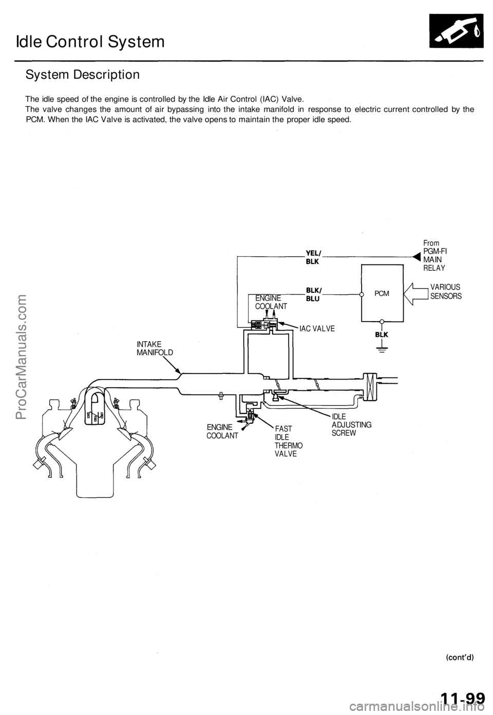
Idle Control System
System Description
The idle speed of the engine is controlled by the Idle Air Control (IAC) Valve.
The valve changes the amount of air bypassing into the intake manifold in response to electric current controlled by the
PCM. When the IAC Valve is activated, the valve opens to maintain the proper idle speed.
ENGINE
COOLANT
IAC VALVE
INTAKE
MANIFOLD
PCM
From
PGM-FI
MAIN
RELAY
FAST
IDLE
THERMO
VALVE
IDLE
ADJUSTING
SCREW
VARIOUS
SENSORS
ENGINE
COOLANTProCarManuals.com
Page 257 of 1771
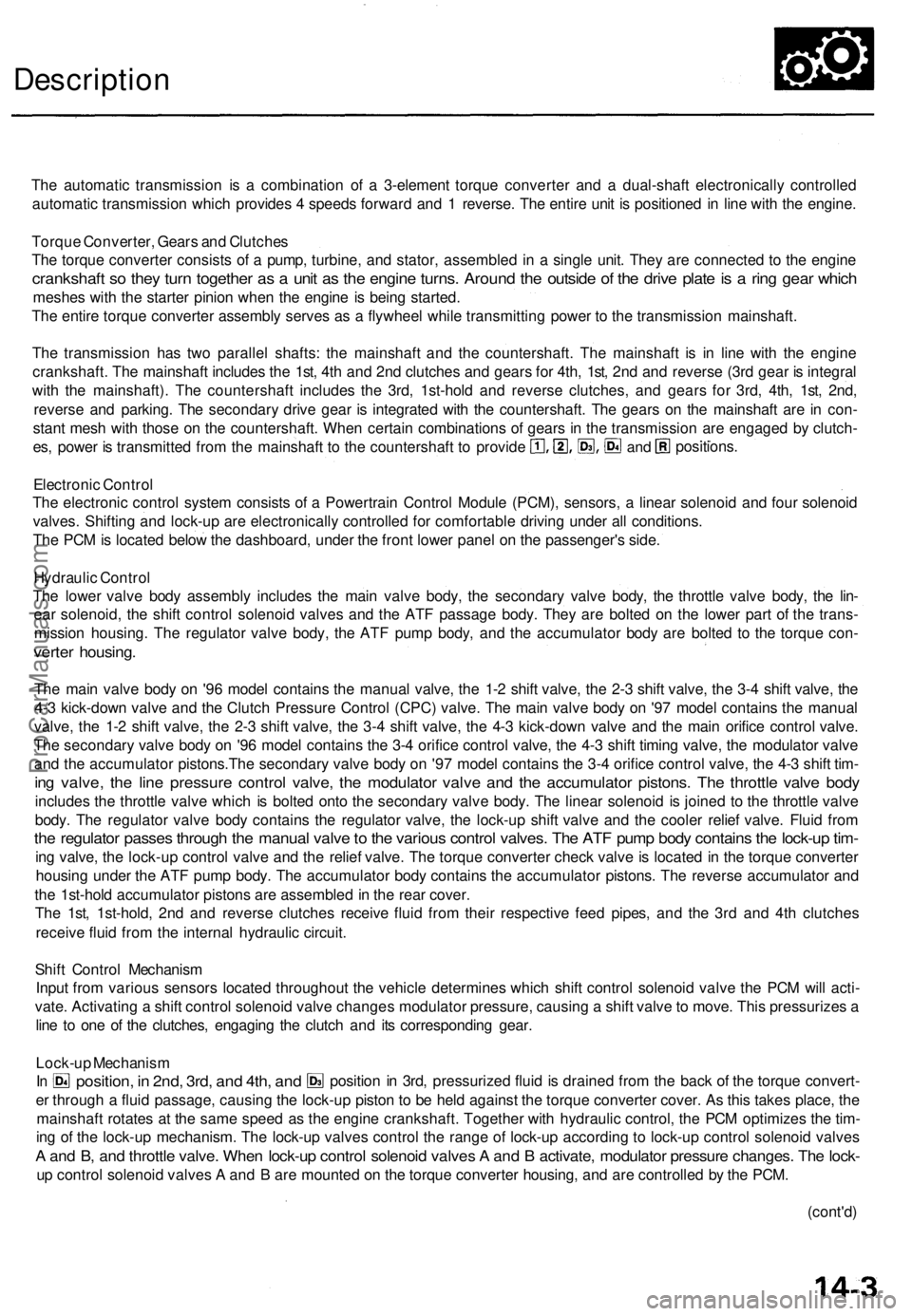
Description
The automatic transmission is a combination of a 3-element torque converter and a dual-shaft electronically controlled
automatic transmission which provides 4 speeds forward and 1 reverse. The entire unit is positioned in line with the engine.
Torque Converter, Gears and Clutches
The torque converter consists of a pump, turbine, and stator, assembled in a single unit. They are connected to the engine
crankshaft so they turn together as a unit as the engine turns. Around the outside of the drive plate is a ring gear which
meshes with the starter pinion when the engine is being started.
The entire torque converter assembly serves as a flywheel while transmitting power to the transmission mainshaft.
The transmission has two parallel shafts: the mainshaft and the countershaft. The mainshaft is in line with the engine
crankshaft. The mainshaft includes the 1st, 4th and 2nd clutches and gears for 4th, 1st, 2nd and reverse (3rd gear is integral
with the mainshaft). The countershaft includes the 3rd, 1st-hold and reverse clutches, and gears for 3rd, 4th, 1st, 2nd,
reverse and parking. The secondary drive gear is integrated with the countershaft. The gears on the mainshaft are in con-
stant mesh with those on the countershaft. When certain combinations of gears in the transmission are engaged by clutch-
positions.
and
es, power is transmitted from the mainshaft to the countershaft to provide
Electronic Control
The electronic control system consists of a Powertrain Control Module (PCM), sensors, a linear solenoid and four solenoid
valves. Shifting and lock-up are electronically controlled for comfortable driving under all conditions.
The PCM is located below the dashboard, under the front lower panel on the passenger's side.
Hydraulic Control
The lower valve body assembly includes the main valve body, the secondary valve body, the throttle valve body, the lin-
ear solenoid, the shift control solenoid valves and the ATF passage body. They are bolted on the lower part of the trans-
mission housing. The regulator valve body, the ATF pump body, and the accumulator body are bolted to the torque con-
verter housing.
The main valve body on '96 model contains the manual valve, the 1-2 shift valve, the 2-3 shift valve, the 3-4 shift valve, the
4-3 kick-down valve and the Clutch Pressure Control (CPC) valve. The main valve body on '97 model contains the manual
valve, the 1-2 shift valve, the 2-3 shift valve, the 3-4 shift valve, the 4-3 kick-down valve and the main orifice control valve.
The secondary valve body on '96 model contains the 3-4 orifice control valve, the 4-3 shift timing valve, the modulator valve
and the accumulator pistons.The secondary valve body on '97 model contains the 3-4 orifice control valve, the 4-3 shift tim-
ing valve, the line pressure control valve, the modulator valve and the accumulator pistons. The throttle valve body
includes the throttle valve which is bolted onto the secondary valve body. The linear solenoid is joined to the throttle valve
body. The regulator valve body contains the regulator valve, the lock-up shift valve and the cooler relief valve. Fluid from
the regulator passes through the manual valve to the various control valves. The ATF pump body contains the lock-up tim-
ing valve, the lock-up control valve and the relief valve. The torque converter check valve is located in the torque converter
housing under the ATF pump body. The accumulator body contains the accumulator pistons. The reverse accumulator and
the 1st-hold accumulator pistons are assembled in the rear cover.
The 1st, 1st-hold, 2nd and reverse clutches receive fluid from their respective feed pipes, and the 3rd and 4th clutches
receive fluid from the internal hydraulic circuit.
Shift Control Mechanism
Input from various sensors located throughout the vehicle determines which shift control solenoid valve the PCM will acti-
vate. Activating a shift control solenoid valve changes modulator pressure, causing a shift valve to move. This pressurizes a
line to one of the clutches, engaging the clutch and its corresponding gear.
er through a fluid passage, causing the lock-up piston to be held against the torque converter cover. As this takes place, the
mainshaft rotates at the same speed as the engine crankshaft. Together with hydraulic control, the PCM optimizes the tim-
ing of the lock-up mechanism. The lock-up valves control the range of lock-up according to lock-up control solenoid valves
A and B, and throttle valve. When lock-up control solenoid valves A and B activate, modulator pressure changes. The lock-
up control solenoid valves A and B are mounted on the torque converter housing, and are controlled by the PCM.
(cont'd)
Lock-up Mechanism
In
position, in 2nd, 3rd, and 4th, and
position in 3rd, pressurized fluid is drained from the back of the torque convert-ProCarManuals.com
Page 276 of 1771

Description
NOTE:
Shift schedule s betwee n 3r d an d 4t h gea r store d i n th e PC M enabl e th e PCM' s fuzz y logi c t o automaticall y selec t th e
mos t suitabl e gea r accordin g t o th e magnitud e o f a gradient .
Fuzz y logi c i s a for m o f artificia l intelligenc e tha t let s computer s respon d t o changin g condition s muc h lik e a huma n
mind would .
Descendin g Contro l
whe n th e throttl e is close d become s faste r tha n th e se t spee d fo r fla t roa d drivin g t o wide n th e 3r d gea r drivin g area .
This, i n combinatio n wit h engin e brakin g fro m th e deceleratio n lock-up , achieve s smoot h drivin g whe n th e vehicl e is
descending .
Ther e ar e tw o descendin g mode s wit h differen t 3r d gea r drivin g area s accordin g t o th e magnitud e o f a gradien t store d i n
th e PCM .
When th e vehicl e is in 4t h gear , an d yo u ar e deceleratin g o n a gradua l hill , o r whe n yo u ar e applyin g th e brake s o n a stee p
hill, the transmissio n will downshif t to 3r d gear . Whe n you accelerate , the transmissio n will the n retur n to 4t h gear .
Electroni c Contro l Syste m (cont'd )
Ascendin g Contro l
3r d gea r t o preven t th e transmissio n fro m frequentl y shiftin g betwee n 3r d an d 4t h gears , s o th e vehicl e ca n ru n smoot h
an d hav e mor e powe r whe n needed . position
, th e syste m extend s th e engagemen t are a o f
Whe n th e PC M determine s tha t th e vehicl e i s climbin g a hil l i n
ASCENDIN G MOD E DESCENDIN G MOD E
Deceleratio n Contro l
Whe n th e vehicl e goe s aroun d a corner , an d need s to decelerat e firs t an d the n accelerate , th e PC M set s th e dat a fo r deceleratio n
contro l t o reduc e th e numbe r o f time s th e transmissio n shifts . Whe n th e vehicl e i s deceleratin g fro m speed s abov e 3 0 mp h
(4 8 km/h) , th e PC M shift s th e transmissio n fro m 4t h to 2n d earlie r tha n norma l t o cop e wit h upcomin g acceleration .
Whe
n th e PC M determine s tha t th e vehicl e i s goin g dow n a hil l i n position , th e shift-u p spee d fro m 3r d t o 4t h gea r
3RD/4T H SHIFTIN GCHARACTERISTIC SCONTROL ARE A
Flat roa dmod e
. Stee p descendin gmode
Gradua l descendin gmode
Vehicl e spee dmph (km/h )Vehicle spee dmph (km/h )
ProCarManuals.com
Page 329 of 1771
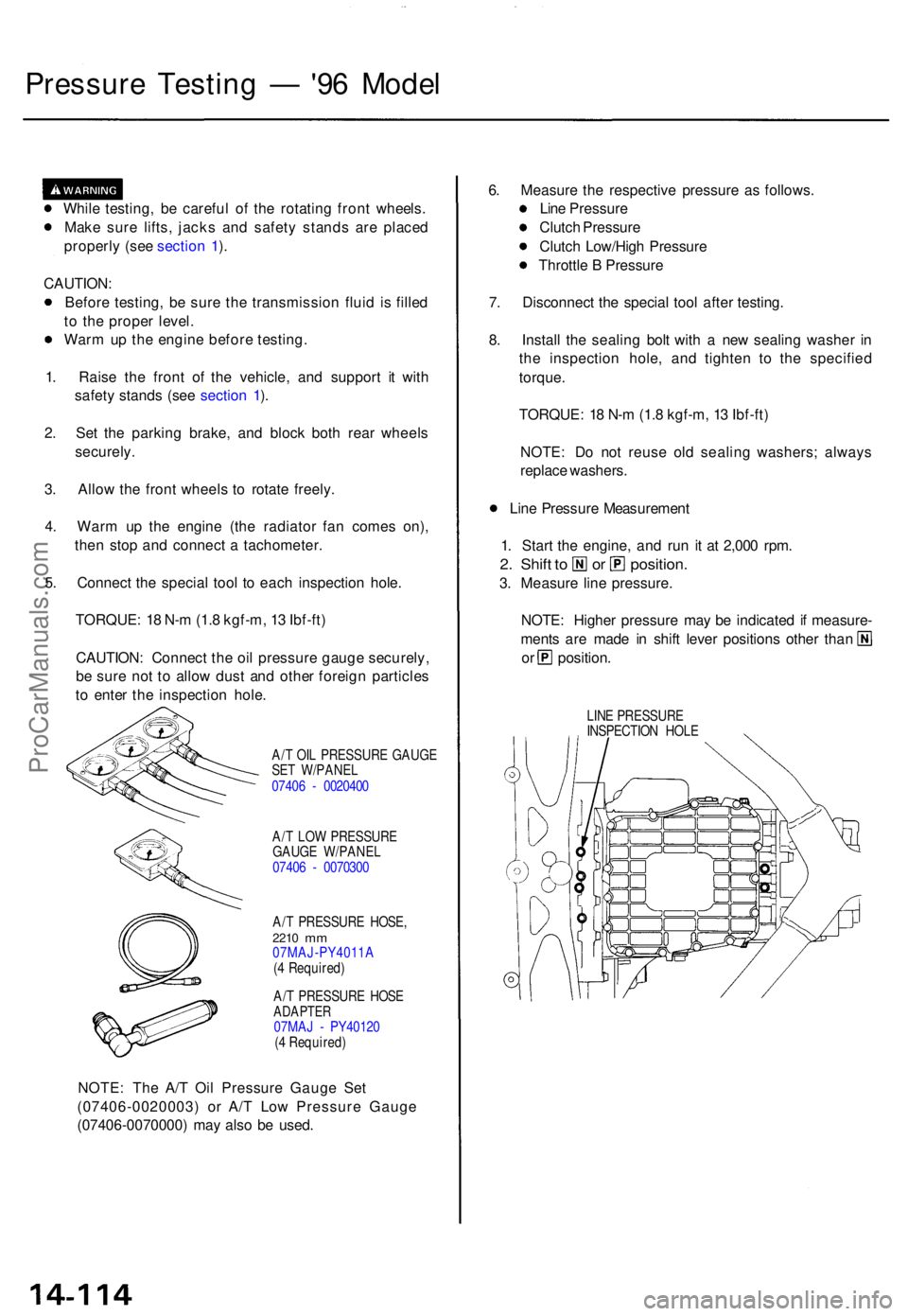
Pressure Testin g — '96 Mode l
While testing , b e carefu l o f th e rotatin g fron t wheels .
Mak e sur e lifts , jack s an d safet y stand s ar e place d
properl y (se e sectio n 1 ).
CAUTION :
Befor e testing , b e sur e th e transmissio n flui d i s fille d
t o th e prope r level .
War m u p th e engin e befor e testing .
1 . Rais e th e fron t o f th e vehicle , an d suppor t i t wit h
safet y stand s (se e sectio n 1 ).
2 . Se t th e parkin g brake , an d bloc k bot h rea r wheel s
securely .
3 . Allo w th e fron t wheel s t o rotat e freely .
4 . War m u p th e engin e (th e radiato r fa n come s on) ,
the n sto p an d connec t a tachometer .
5 . Connec t th e specia l too l t o eac h inspectio n hole .
TORQUE : 1 8 N- m (1. 8 kgf-m , 1 3 Ibf-ft )
CAUTION : Connec t th e oi l pressur e gaug e securely ,
b e sur e no t t o allo w dus t an d othe r foreig n particle s
t o ente r th e inspectio n hole .
A/T OI L PRESSUR E GAUG E
SE T W/PANE L
0740 6 - 002040 0
A/ T LO W PRESSUR E
GAUG E W/PANE L
0740 6 - 007030 0
A/ T PRESSUR E HOSE ,
2210 mm07MAJ-PY4011 A
( 4 Required )
A/ T PRESSUR E HOS E
ADAPTE R07MAJ - PY4012 0
( 4 Required )
NOTE: Th e A/ T Oi l Pressur e Gaug e Se t
(07406-0020003 ) o r A/ T Lo w Pressur e Gaug e
(07406-0070000 ) ma y als o b e used . 6
. Measur e th e respectiv e pressur e a s follows .
Lin e Pressur e
Clutc h Pressur e
Clutc h Low/Hig h Pressur e
Throttl e B Pressur e
7 . Disconnec t th e specia l too l afte r testing .
8 . Instal l th e sealin g bol t wit h a ne w sealin g washe r i n
th e inspectio n hole , an d tighte n t o th e specifie d
torque .
TORQUE : 1 8 N- m (1. 8 kgf-m , 1 3 Ibf-ft )
NOTE : D o no t reus e ol d sealin g washers ; alway s
replac e washers .
Lin e Pressur e Measuremen t
1 . Star t th e engine , an d ru n i t a t 2,00 0 rpm .
2. Shif t t o o r position .
3. Measur e lin e pressure .
NOTE : Highe r pressur e ma y b e indicate d if measure -
ments ar e mad e i n shif t leve r position s othe r tha n
or position .
LINE PRESSUR E
INSPECTIO N HOL E
ProCarManuals.com
Page 335 of 1771
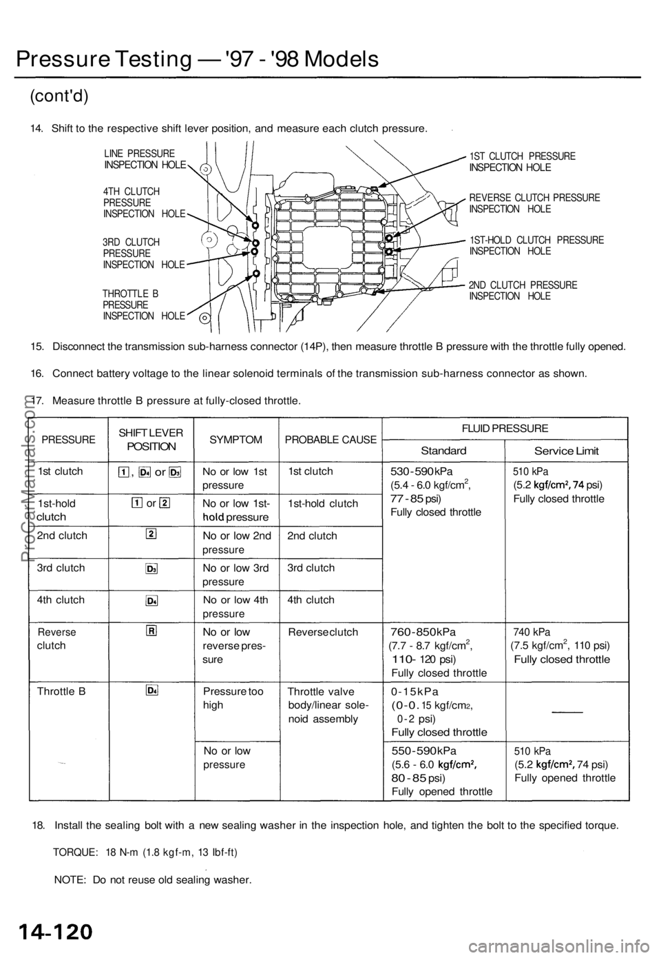
Pressure Testin g — '97 - '9 8 Model s
(cont'd )
14. Shif t t o th e respectiv e shif t leve r position , an d measur e eac h clutc h pressure .
LINE PRESSUR EINSPECTION HOL E
4TH CLUTC H
PRESSUR E
INSPECTIO N HOL E
3R D CLUTC H
PRESSUR E
INSPECTIO N HOL E
THROTTL E B
PRESSUR E
INSPECTIO N HOL E 1S
T CLUTC H PRESSUR E
INSPECTION HOL E
REVERS E CLUTC H PRESSUR E
INSPECTIO N HOL E
1ST-HOL D CLUTC H PRESSUR E
INSPECTIO N HOL E
2N D CLUTC H PRESSUR E
INSPECTIO N HOL E
15. Disconnec t th e transmissio n sub-harnes s connecto r (14P) , the n measur e throttl e B pressur e wit h th e throttl e full y opened .
16 . Connec t batter y voltag e to th e linea r solenoi d terminal s o f th e transmissio n sub-harnes s connecto r a s shown .
17 . Measur e throttl e B pressur e a t fully-close d throttle .
PRESSUR E
1st clutc h
1st-hol d
clutch
2nd clutc h
3r d clutc h
4t h clutc h
Revers e
clutch
Throttl e B SHIF
T LEVE R
POSITIO N
, o r
or
SYMPTO M
No o r lo w 1s t
pressur e
No o r lo w 1st -
hold pressur e
No o r lo w 2n d
pressur e
No o r lo w 3r d
pressur e
No o r lo w 4t h
pressur e
No o r lo w
revers e pres -
sur e
Pressur e to o
hig h
No o r lo w
pressur e
PROBABL E CAUS E
1st clutc h
1st-hol d clutc h
2n d clutc h
3r d clutc h
4t h clutc h
Revers e clutc h
Throttl e valv e
body/linea r sole -
noi d assembl y FLUI
D PRESSUR E
Standard
530 - 59 0 kP a
(5.4 - 6. 0 kgf/cm2,
77 - 8 5 psi )
Full y close d throttl e
760 - 85 0 kP a
(7.7 - 8. 7 kgf/cm2,
110 - 120 psi )
Full y close d throttl e
0-15kP a
(0-0. 15 kgf/cm2,
0-2 psi )
Fully close d throttl e
550 - 59 0 kP a
(5.6 - 6. 0 kgf/cm2,
80 - 8 5 psi )
Full y opene d throttl e
Service Limi t
510 kP a
(5.2 kgf/cm2, 74 psi )
Full y close d throttl e
740 kP a
(7.5 kgf/cm2, 11 0 psi )
Full y close d throttl e
510 kP a
(5.2 kgf/cm2, 74 psi )
Full y opene d throttl e
18 . Instal l th e sealin g bol t wit h a ne w sealin g washe r i n th e inspectio n hole , an d tighte n th e bol t t o th e specifie d torque .
TORQUE : 1 8 N- m (1. 8 kgf-m , 1 3 Ibf-ft )
NOTE : D o no t reus e ol d sealin g washer .
ProCarManuals.com