1995 ACURA TL ESP
[x] Cancel search: ESPPage 1207 of 1771
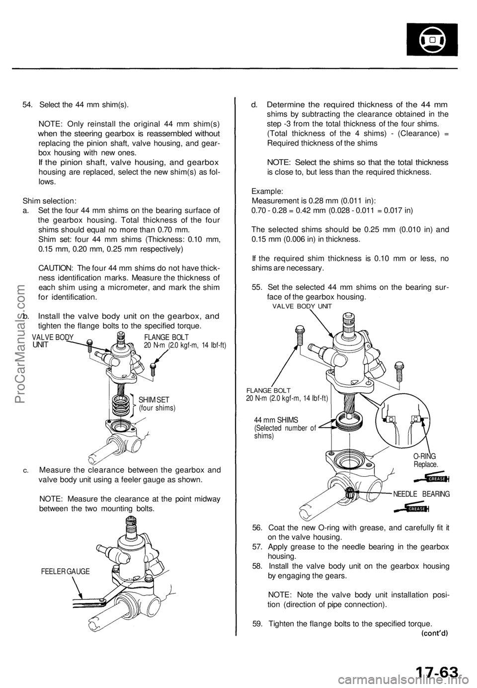
54. Selec t th e 4 4 m m shim(s) .
NOTE : Onl y reinstal l th e origina l 4 4 m m shim(s )
when th e steerin g gearbo x i s reassemble d withou t
replacin g th e pinio n shaft , valv e housing , an d gear -
bo x housin g wit h ne w ones .
If th e pinio n shaft , valv e housing , an d gearbo x
housing ar e replaced , selec t th e ne w shim(s ) a s fol -
lows .
Shi m selection :
a . Se t th e fou r 4 4 m m shim s o n th e bearin g surfac e o f
th e gearbo x housing . Tota l thicknes s o f th e fou r
shim s shoul d equa l n o mor e tha n 0.7 0 mm .
Shi m set : fou r 4 4 m m shim s (Thickness : 0.1 0 mm ,
0.1 5 mm , 0.2 0 mm , 0.2 5 m m respectively )
CAUTION : Th e fou r 4 4 m m shim s d o no t hav e thick -
nes s identificatio n marks . Measur e th e thicknes s o f
eac h shi m usin g a micrometer , an d mar k th e shi m
fo r identification .
b. Instal l th e valv e bod y uni t o n th e gearbox , an d
tighte n th e flang e bolt s t o th e specifie d torque .
SHIM SET(fou r shims )
c.Measur e th e clearanc e betwee n th e gearbo x an d
valv e bod y uni t usin g a feele r gaug e a s shown .
NOTE : Measur e th e clearanc e a t th e poin t midwa y
betwee n th e tw o mountin g bolts .
FEELE R GAUG E
d. Determin e th e require d thicknes s o f th e 4 4 m m
shim s b y subtractin g th e clearanc e obtaine d i n th e
ste p - 3 fro m th e tota l thicknes s o f th e fou r shims .
(Tota l thicknes s o f th e 4 shims ) - (Clearance ) =
Require d thicknes s o f th e shim s
NOTE : Selec t th e shim s s o tha t th e tota l thicknes s
is clos e to , bu t les s tha n th e require d thickness .
Example:
Measuremen t i s 0.2 8 m m (0.01 1 in) :
0.7 0 - 0.2 8 = 0.4 2 m m (0.02 8 - 0.01 1 = 0.01 7 in )
Th e selecte d shim s shoul d b e 0.2 5 m m (0.01 0 in ) an d
0.1 5 m m (0.00 6 in ) i n thickness .
I f th e require d shi m thicknes s i s 0.1 0 m m o r less , n o
shim s ar e necessary .
55 . Se t th e selecte d 4 4 m m shim s o n th e bearin g sur -
fac e o f th e gearbo x housing .
FLANGE BOL T20 N- m (2. 0 kgf-m , 1 4 Ibf-ft )
44 m m SHIM S(Selecte d numbe r o f
shims )
56. Coa t th e ne w O-rin g wit h grease , an d carefull y fi t i t
o n th e valv e housing .
57 . Appl y greas e t o th e needl e bearin g i n th e gearbo x
housing .
58 . Instal l th e valv e bod y uni t o n th e gearbo x housin g
b y engagin g th e gears .
NOTE : Not e th e valv e bod y uni t installatio n posi -
tio n (directio n o f pip e connection) .
59 . Tighte n th e flang e bolt s t o th e specifie d torque .
VALVE BOD YUNITFLANG E BOL T
2 0 N- m (2. 0 kgf-m , 1 4 Ibf-ft )
NEEDLE BEARIN G
O-RIN
G
Replace .
VALVE BOD Y UNI T
ProCarManuals.com
Page 1286 of 1771
Anti-lock Brake System (ABS)
Features/Construction
In a conventional brake system, if the brake pedal is depressed very hard, the wheels can lock before the vehicle comes to
a stop. In such a case, the stability of the vehicle is reduced if the rear wheels are locked, and maneuverability of the vehi-
cle is reduced if the front wheels are locked, creating an extremely unstable condition.
The Anti-lock Brake System (ABS) modulates the pressure of the brake fluid applied to each front caliper or both rear
calipers, thereby preventing the locking of the wheels, whenever the wheels are likely to be locked due to hard braking. It
then restores normal hydraulic pressure when there is no longer any possibility of wheel locking.
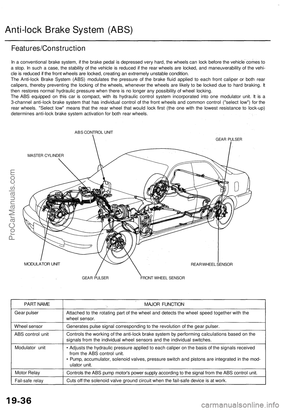
The ABS equipped on this car is compact, with its hydraulic control system incorporated into one modulator unit. It is a
3-channel anti-lock brake system that has individual control of the front wheels and common control ("select low") for the
rear wheels. "Select low" means that the rear wheel that would lock first (the one with the lowest resistance to lock-up)
determines anti-lock brake system activation for both rear wheels.
ABS CONTROL UNIT
GEAR PULSER
MASTER CYLINDER
MODULATOR UNIT
REAR WHEEL SENSOR
GEAR PULSER
FRONT WHEEL SENSOR
PART NAME
Gear pulser
Wheel sensor
ABS control unit
Modulator unit
Motor Relay
Fail-safe relay
MAJOR FUNCTION
Attached to the rotating part of the wheel and detects the wheel speed together with the
wheel sensor.
Generates pulse signal corresponding to the revolution of the gear pulser.
Controls the working of the anti-lock brake system by performing calculations based on the
signals from the individual wheel sensors and the individual switches.
• Adjusts the hydraulic pressure applied to each caliper on the basis of the signals received
from the ABS control unit.
• Pump, accumulator, solenoid valves, pressure switch and pistons are integrated in the mod-
ulator unit.
Controls the ABS pump motor's power supply according to the signal from the ABS control unit.
Cuts off the solenoid valve ground circuit when the fail-safe device is at work.ProCarManuals.com
Page 1313 of 1771
Wire Harnes s Replacemen t
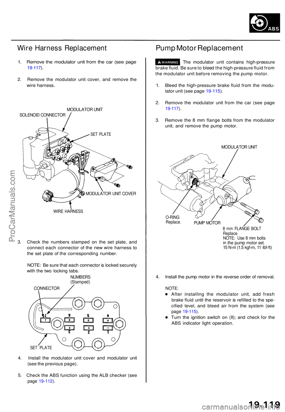
1. Remov e th e modulato r uni t fro m th e ca r (se e pag e
19-117 ).
2 . Remov e th e modulato r uni t cover , an d remov e th e
wir e harness .
MODULATO R UNI T
SOLENOI D CONNECTO R
SET PLAT E
MODULATO R UNI T COVE R
WIRE HARNES S
3. Chec k th e number s stampe d o n th e se t plate , an d
connec t eac h connecto r o f th e ne w wir e harnes s t o
th e se t plat e o f th e correspondin g number .
NOTE : B e sur e tha t eac h connecto r i s locke d securel y
wit h th e tw o lockin g tabs .
NUMBER S(Stamped )
CONNECTO R
SET PLAT E
4. Instal l th e modulato r uni t cove r an d modulato r uni t
(se e th e previou s page) .
5 . Chec k th e AB S functio n usin g th e AL B checke r (se e
page 19-112 ).
Pum p Moto r Replacemen t
The modulato r uni t contain s high-pressur e
brak e fluid . B e sur e to blee d th e high-pressur e flui d fro m
th e modulato r uni t befor e removin g th e pum p motor .
1 . Blee d th e high-pressur e brak e flui d fro m th e modu -
lato r uni t (se e pag e 19-115 ).
2 . Remov e th e modulato r uni t fro m th e ca r (se e pag e
19-117 ).
3 . Remov e th e 8 m m flang e bolt s fro m th e modulato r
unit , an d remov e th e pum p motor .
MODULATO R UNI T
O-RIN GReplace .PUMP MOTO R
8 m m FLANG E BOL TReplace .NOTE: Us e 8 m m bolt sin th e pum p moto r set .15 N- m (1. 5 kgf-m , 1 1 Ibf-ft )
4. Instal l th e pum p moto r i n th e revers e orde r o f removal .
NOTE:
After installin g th e modulato r unit , ad d fres h
brak e flui d unti l th e reservoi r i s refille d t o th e spe -
cifie d level , an d blee d ai r fro m th e syste m (se e
page 19-115 ).
Tur n th e ignitio n switc h o n (II) ; an d chec k fo r th e
AB S indicato r ligh t operation .
ProCarManuals.com
Page 1484 of 1771
Rear Windo w
Remova l (cont'd )
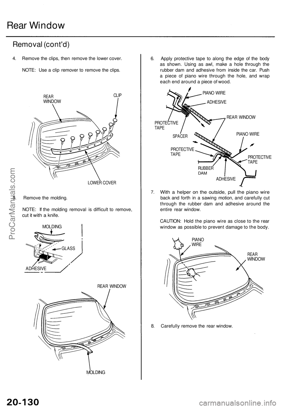
4. Remov e th e clips , the n remov e th e lowe r cover .
NOTE : Us e a cli p remove r t o remov e th e clips .
REARWINDO W
CLIP
LOWE R COVE R
5. Remov e th e molding .
NOTE : I f th e moldin g remova l i s difficul t t o remove ,
cut i t wit h a knife .
MOLDIN G
REAR WINDO W
MOLDING
6. Appl y protectiv e tap e t o alon g th e edg e o f th e bod y
a s shown . Usin g a s awl , mak e a hol e throug h th e
rubbe r da m an d adhesiv e fro m insid e th e car . Pus h
a piec e o f pian o wir e throug h th e hole , an d wra p
eac h en d aroun d a piec e o f wood .
PIANO WIR E
ADHESIV E
REAR WINDO W
PROTECTIV ETAPE
PROTECTIV ETAPEPROTECTIV ETAPE
RUBBE RDAM
ADHESIV E
7.Wit h a helpe r o n th e outside , pul l th e pian o wir e
back an d fort h i n a sawin g motion , an d carefull y cu t
throug h th e rubbe r da m an d adhesiv e aroun d th e
entir e rea r window .
CAUTION : Hol d th e pian o wir e a s clos e t o th e rea r
windo w a s possibl e to preven t damag e to th e body .
REARWINDO W
8. Carefull y remov e th e rea r window .
PIANO WIR ESPACE R
GLASS
ADHESIV E
PIANOWIRE
ProCarManuals.com
Page 1495 of 1771
Troubleshooting
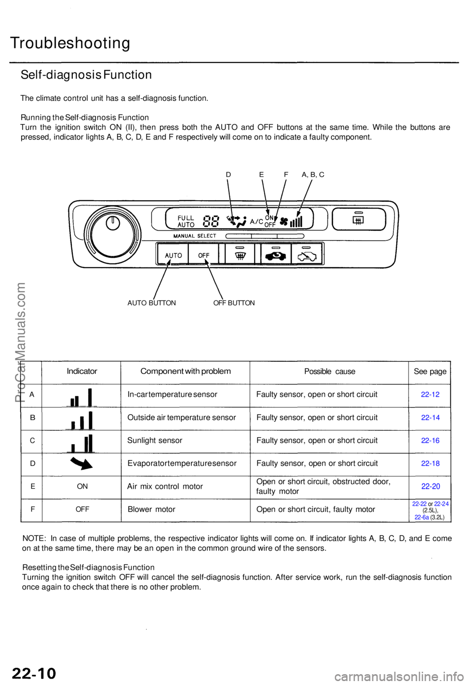
Self-diagnosis Functio n
The climat e contro l uni t ha s a self-diagnosi s function .
Runnin g th e Self-diagnosi s Functio n
Tur n th e ignitio n switc h O N (II) , the n pres s bot h th e AUT O an d OF F button s a t th e sam e time . Whil e th e button s ar e
pressed , indicato r light s A , B , C , D , E an d F respectivel y wil l com e o n to indicat e a fault y component .
AUTO BUTTO NOFF BUTTO N
A
B
C
D
E
F
Indicator
ON
OF F
Componen t wit h proble m
In-car temperatur e senso r
Outsid e ai r temperatur e senso r
Sunligh t senso r
Evaporato r temperatur e senso r
Ai r mi x contro l moto r
Blowe r moto r Possibl
e caus e
Fault y sensor , ope n o r shor t circui t
Fault y sensor , ope n o r shor t circui t
Fault y sensor , ope n o r shor t circui t
Fault y sensor , ope n o r shor t circui t
Ope n o r shor t circuit , obstructe d door ,
fault y moto r
Ope n o r shor t circuit , fault y moto r Se
e pag e22-1 2
22-1 4
22-16
22-1 8
22-2 0
22-22 or 22- 24
(2.5L),
NOTE : I n cas e o f multipl e problems , th e respectiv e indicato r light s wil l com e on . I f indicato r light s A , B , C , D , an d E com e
o n a t th e sam e time , ther e ma y b e a n ope n in th e commo n groun d wir e o f th e sensors .
Resettin g th e Self-diagnosi s Functio n
Turnin g th e ignitio n switc h OF F wil l cance l th e self-diagnosi s function . Afte r servic e work , ru n th e self-diagnosi s functio n
onc e agai n to chec k tha t ther e is n o othe r problem.
D E F A, B , C
22-6a (3.2L)
ProCarManuals.com
Page 1537 of 1771
Troubleshooting
Tips and Precautions (cont'd)
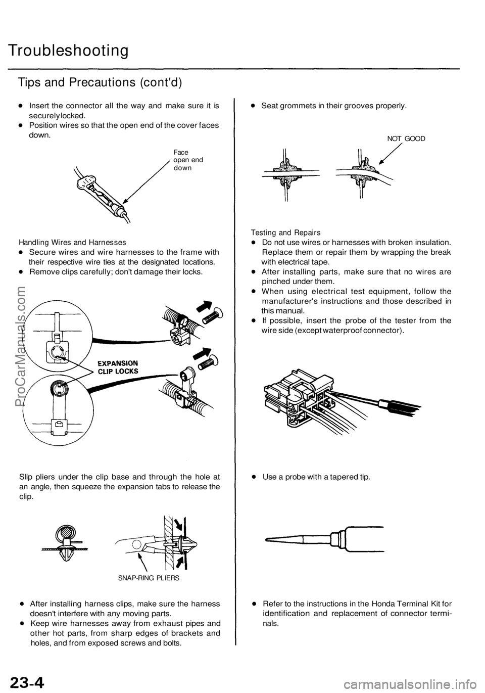
Insert the connector all the way and make sure it is
securely locked.
Position wires so that the open end of the cover faces
down.
Face
open end
down
Handling Wires and Harnesses
Secure wires and wire harnesses to the frame with
their respective wire ties at the designated locations.
Remove clips carefully; don't damage their locks.
Slip pliers under the clip base and through the hole at
an angle, then squeeze the expansion tabs to release the
clip.
SNAP-RING PLIERS
After installing harness clips, make sure the harness
doesn't interfere with any moving parts.
Keep wire harnesses away from exhaust pipes and
other hot parts, from sharp edges of brackets and
holes, and from exposed screws and bolts.
Seat grommets in their grooves properly.
NOT GOOD
Testing and Repairs
Do not use wires or harnesses with broken insulation.
Replace them or repair them by wrapping the break
with electrical tape.
After installing parts, make sure that no wires are
pinched under them.
When using electrical test equipment, follow the
manufacturer's instructions and those described in
this manual.
If possible, insert the probe of the tester from the
wire side (except waterproof connector).
Use a probe with a tapered tip.
Refer to the instructions in the Honda Terminal Kit for
identification and replacement of connector termi-
nals.ProCarManuals.com
Page 1567 of 1771
Ignition Syste m
Descriptio n
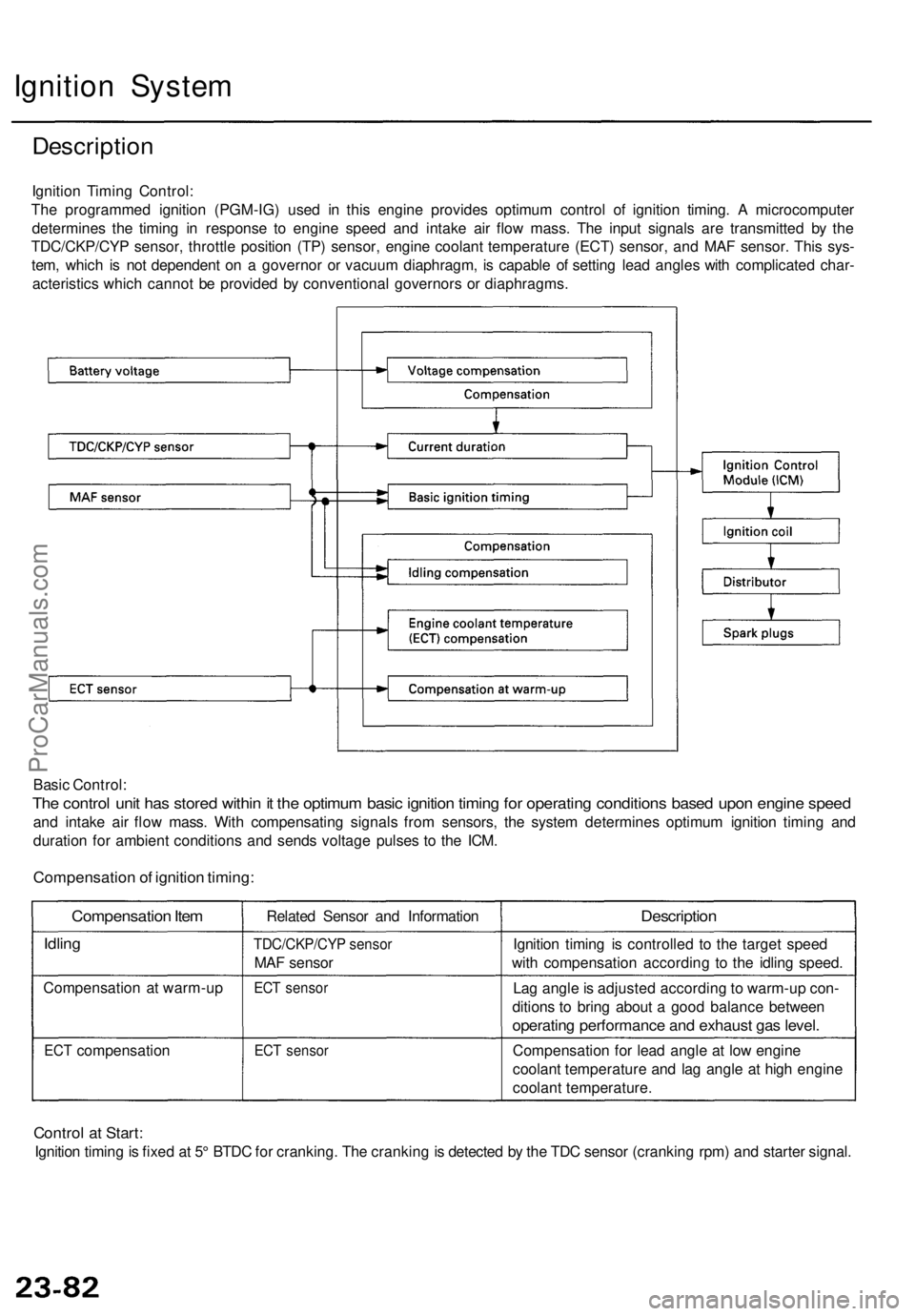
Ignition Timin g Control :
Th e programme d ignitio n (PGM-IG ) use d i n thi s engin e provide s optimu m contro l o f ignitio n timing . A microcompute r
determine s th e timin g i n respons e t o engin e spee d an d intak e ai r flo w mass . Th e inpu t signal s ar e transmitte d b y th e
TDC/CKP/CY P sensor , throttl e positio n (TP ) sensor , engine coolant temperatur e (ECT ) sensor , an d MA F sensor . Thi s sys -
tem , whic h i s no t dependen t o n a governo r o r vacuu m diaphragm , i s capabl e o f settin g lea d angle s wit h complicate d char -
acteristic s whic h canno t b e provide d b y conventiona l governor s o r diaphragms .
Basi c Control :
The contro l uni t ha s store d withi n it th e optimu m basi c ignitio n timin g fo r operatin g condition s base d upo n engin e spee d
and intak e ai r flo w mass . Wit h compensatin g signal s fro m sensors , th e syste m determine s optimu m ignitio n timin g an d
duratio n fo r ambien t condition s an d send s voltag e pulse s t o th e ICM .
Compensatio n of ignitio n timing :
Compensatio n Ite m
Idlin g
Compensatio n a t warm-u p
ECT compensatio n Relate
d Senso r an d Informatio n
TDC/CKP/CY P senso r
MAF senso r
ECT senso r
ECT senso r
Descriptio n
Ignition timin g i s controlle d t o th e targe t spee d
wit h compensatio n accordin g t o th e idlin g speed .
La g angl e is adjuste d accordin g t o warm-u p con -
dition s t o brin g abou t a goo d balanc e betwee n
operating performanc e an d exhaus t ga s level .
Compensatio n fo r lea d angl e a t lo w engin e
coolan t temperatur e an d la g angl e a t hig h engin e
coolan t temperature .
Control a t Start :
Ignitio n timin g is fixe d a t 5 ° BTD C fo r cranking . Th e crankin g is detecte d b y th e TD C senso r (crankin g rpm ) an d starte r signal .
ProCarManuals.com
Page 1716 of 1771
Description
The cruise control system uses mechanically and electri-
cally operated devices to maintain vehicle speed at a
setting selected by the driver.
The cruise control unit receives command signals from
the cruise control main switch and the cruise control
set/resume/cancel switch. It receives information about
operating conditions from the brake switch, ECM, vehi-
cle speed sensor (VSS), or the A/T gear position switch.
The cruise control unit sends operational signals to the
devices that regulate the throttle position. The throttle
position maintains the selected vehicle speed.
Essentially, the control unit compares the actual speed
of the vehicle to the selected speed. Then, the control
unit uses the result of that comparison to open or close
the throttle.
The brake switch releases the system's control of the
throttle at the instant the driver depresses the brake
pedal. The switch sends an electronic signal to the con-
trol unit when the brake pedal is depressed; the control
unit responds by allowing the throttle to close. The A/T
gear position switch sends a disengage signal input to
the control unit that also allows the throttle to close.
Operation:
The cruise control system will set and automatically
maintain any speed above 25 mph (40 km/h). To set a
speed, make sure that the main switch is in the "ON"
position. After reaching the desired speed, press the set
switch. The cruise control unit will receive a set signal
and, in turn, will actuate the cruise control actuator. If
you depress the set switch is when the cruise control
system is on, the "cruise light", an indicator in the
gauge assembly, will come on. You can cancel the
cruise control system by depressing the cancel switch or
by pushing the main switch to "OFF". This removes
power to the control unit and erases the set speed from
memory. If the system is disengaged temporarily by the
brake switch or the A/T gear position switch and vehicle
speed is still above 25 mph (40 km/h), press the resume
switch. With the resume switch depressed and the set
memory retained, the vehicle will automatically return
to the previous set speed.
For gradual acceleration without depressing the acceler-
ator pedal, push the resume switch down and hold it
there until the desired speed is reached. This will send
an acceleration signal to the control unit. When the
switch is released, the system will be reprogrammed for
the new speed. To slow the vehicle down, depress the
set switch. This will send a deceleration signal to the
control unit, causing the vehicle to coast. When you
reach the desired speed, release the set switch. This will
reprogram the system for the new speed.ProCarManuals.com