1995 ACURA TL four wheel drive
[x] Cancel search: four wheel drivePage 257 of 1771

Description
The automatic transmission is a combination of a 3-element torque converter and a dual-shaft electronically controlled
automatic transmission which provides 4 speeds forward and 1 reverse. The entire unit is positioned in line with the engine.
Torque Converter, Gears and Clutches
The torque converter consists of a pump, turbine, and stator, assembled in a single unit. They are connected to the engine
crankshaft so they turn together as a unit as the engine turns. Around the outside of the drive plate is a ring gear which
meshes with the starter pinion when the engine is being started.
The entire torque converter assembly serves as a flywheel while transmitting power to the transmission mainshaft.
The transmission has two parallel shafts: the mainshaft and the countershaft. The mainshaft is in line with the engine
crankshaft. The mainshaft includes the 1st, 4th and 2nd clutches and gears for 4th, 1st, 2nd and reverse (3rd gear is integral
with the mainshaft). The countershaft includes the 3rd, 1st-hold and reverse clutches, and gears for 3rd, 4th, 1st, 2nd,
reverse and parking. The secondary drive gear is integrated with the countershaft. The gears on the mainshaft are in con-
stant mesh with those on the countershaft. When certain combinations of gears in the transmission are engaged by clutch-
positions.
and
es, power is transmitted from the mainshaft to the countershaft to provide
Electronic Control
The electronic control system consists of a Powertrain Control Module (PCM), sensors, a linear solenoid and four solenoid
valves. Shifting and lock-up are electronically controlled for comfortable driving under all conditions.
The PCM is located below the dashboard, under the front lower panel on the passenger's side.
Hydraulic Control
The lower valve body assembly includes the main valve body, the secondary valve body, the throttle valve body, the lin-
ear solenoid, the shift control solenoid valves and the ATF passage body. They are bolted on the lower part of the trans-
mission housing. The regulator valve body, the ATF pump body, and the accumulator body are bolted to the torque con-
verter housing.
The main valve body on '96 model contains the manual valve, the 1-2 shift valve, the 2-3 shift valve, the 3-4 shift valve, the
4-3 kick-down valve and the Clutch Pressure Control (CPC) valve. The main valve body on '97 model contains the manual
valve, the 1-2 shift valve, the 2-3 shift valve, the 3-4 shift valve, the 4-3 kick-down valve and the main orifice control valve.
The secondary valve body on '96 model contains the 3-4 orifice control valve, the 4-3 shift timing valve, the modulator valve
and the accumulator pistons.The secondary valve body on '97 model contains the 3-4 orifice control valve, the 4-3 shift tim-
ing valve, the line pressure control valve, the modulator valve and the accumulator pistons. The throttle valve body
includes the throttle valve which is bolted onto the secondary valve body. The linear solenoid is joined to the throttle valve
body. The regulator valve body contains the regulator valve, the lock-up shift valve and the cooler relief valve. Fluid from
the regulator passes through the manual valve to the various control valves. The ATF pump body contains the lock-up tim-
ing valve, the lock-up control valve and the relief valve. The torque converter check valve is located in the torque converter
housing under the ATF pump body. The accumulator body contains the accumulator pistons. The reverse accumulator and
the 1st-hold accumulator pistons are assembled in the rear cover.
The 1st, 1st-hold, 2nd and reverse clutches receive fluid from their respective feed pipes, and the 3rd and 4th clutches
receive fluid from the internal hydraulic circuit.
Shift Control Mechanism
Input from various sensors located throughout the vehicle determines which shift control solenoid valve the PCM will acti-
vate. Activating a shift control solenoid valve changes modulator pressure, causing a shift valve to move. This pressurizes a
line to one of the clutches, engaging the clutch and its corresponding gear.
er through a fluid passage, causing the lock-up piston to be held against the torque converter cover. As this takes place, the
mainshaft rotates at the same speed as the engine crankshaft. Together with hydraulic control, the PCM optimizes the tim-
ing of the lock-up mechanism. The lock-up valves control the range of lock-up according to lock-up control solenoid valves
A and B, and throttle valve. When lock-up control solenoid valves A and B activate, modulator pressure changes. The lock-
up control solenoid valves A and B are mounted on the torque converter housing, and are controlled by the PCM.
(cont'd)
Lock-up Mechanism
In
position, in 2nd, 3rd, and 4th, and
position in 3rd, pressurized fluid is drained from the back of the torque convert-ProCarManuals.com
Page 660 of 1771

Airbag
Replacement (cont'd)
CAUTION: Be sure to install the SRS wiring so that it is
not pinched or interfering with other parts.
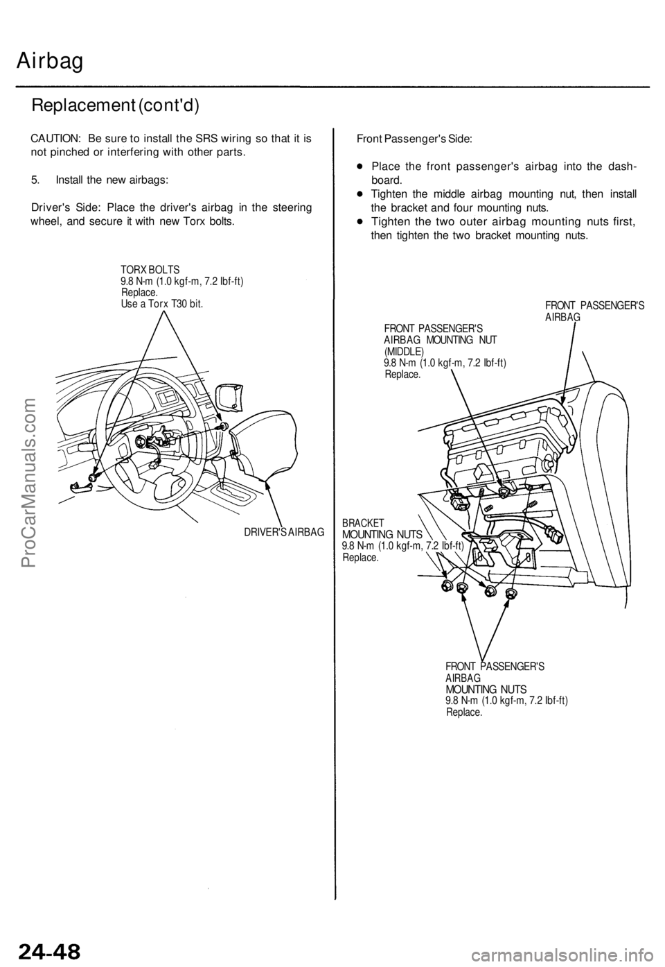
5. Install the new airbags:
Driver's Side: Place the driver's airbag in the steering
wheel, and secure it with new Torx bolts.
TORX BOLTS
9.8 N-m (1.0 kgf-m, 7.2 Ibf-ft)
Replace.
Use a Torx T30 bit.
DRIVER'S AIRBAG
Front Passenger's Side:
Place the front passenger's airbag into the dash-
board.
Tighten the middle airbag mounting nut, then install
the bracket and four mounting nuts.
Tighten the two outer airbag mounting nuts first,
then tighten the two bracket mounting nuts.
FRONT PASSENGER'S
AIRBAG
FRONT PASSENGER'S
AIRBAG MOUNTING NUT
(MIDDLE)
9.8 N-m (1.0 kgf-m, 7.2 Ibf-ft)
Replace.
BRACKET
MOUNTING NUTS
9.8 N-m (1.0 kgf-m, 7.2 Ibf-ft)
Replace.
FRONT PASSENGER'S
AIRBAG
MOUNTING NUTS
9.8 N-m (1.0 kgf-m, 7.2 Ibf-ft)
Replace.ProCarManuals.com
Page 936 of 1771

Description
The automatic transmission is a combination of a 3-element torque converter and a dual-shaft electronically controlled
automatic transmission which provides 4 speeds forward and 1 reverse. The entire unit is positioned in line with the engine.
Torque Converter, Gears and Clutches
The torque converter consists of a pump, turbine and stator, assembled in a single unit.
They are connected to the engine crankshaft so they turn together as a unit as the engine turns.
Around the outside of the drive plate is a ring gear which meshes with the starter pinion when the engine is being started.
The entire torque converter assembly serves as a flywheel while transmitting power to the transmission mainshaft.
The transmission has two parallel shafts: the mainshaft and the countershaft. The mainshaft is in line with the engine
crankshaft.
The mainshaft includes the 1st, 2nd and 4th clutches, and gears for 4th, 2nd, 1st and reverse (3rd gear is integral with the
mainshaft, while the reverse gear is integral with 4th gear).
The countershaft includes the 3rd, and 1st-hold clutches, and gears for 3rd, 4th, 1st, 2nd, reverse, and parking. The sec-
ondary drive gear is integrated with the countershaft.
The gears on the mainshaft are in constant mesh with those on the countershaft.
When certain combinations of gears in the transmission are engaged by clutches, power is transmitted from the mainshaft
to the countershaft to provide and positions.
Electronic Control
The electronic control system consists of the Transmission Control Module (TCM), sensors, a linear solenoid and four
solenoid valves. Shifting and lock-up are electronically controlled for comfortable driving under all conditions.
The TCM is located below the dashboard, behind the glove box on the passenger's side.
Hydraulic Control
The lower valve body assembly includes the main valve body, the servo body and the shift control solenoid valves. They
are bolted on the lower part of the transmission housing.
Other valve bodies, the regulator valve body, the ATF pump body, the 2nd accumulator body, and the throttle valve body,
are bolted to the torque converter housing.
The main valve body contains the manual valve, the 1 - 2 shift valve, the 2 - 3 shift valve, the 3 - 4 shift valve, the 4th kick-
down valve, the 2 - 3 orifice control valve, the 3 - 4 orifice control valve, the 4th exhaust valve, the servo control valve,
and the main orifice control valve.
The servo body contains the servo valve, 3rd and 4th accumulator pistons.
The regulator valve body contains the regulator valve, the lock-up shift valve, and the cooler relief valve.
Fluid from the regulator passes through the manual valve to the various control valves.
The throttle valve body includes the throttle valve which is bolted onto the 2nd accumulator body. The 2nd accumulator
piston is assembled in the 2nd accumulator body.
The linear solenoid is joined with the throttle valve body.
The ATF pump body contains the modulator valve, the lock-up control valve, the lock-up timing valve, and the relief valve.
The torque converter check valve is located in the torque converter housing under the ATF pump body.
The 1st and 1st-hold accumulator pistons are assembled in the rear cover.
The clutches receive fluid from their respective feed pipes or internal hydraulic circuit.
Shift Control Mechanism
Input from various sensors located throughout the vehicle determines which shift control solenoid valve the TCM will acti-
vate. Activating a shift control solenoid valve changes modulator pressure, causing a shift valve to move. This pressurizes
a line to one of the clutches, engaging that clutch and its corresponding gear.
Lock-up Mechanism
In position, in 2nd, 3rd and 4th, and in position in 3rd, pressurized fluid is drained from the back of the torque con-
verter through a fluid passage, causing the lock-up piston to be held against the torque converter cover. As this takes place,
the mainshaft rotates at the same speed as the engine crankshaft. Together with hydraulic control, the TCM optimizes the
timing of the lock-up mechanism. The lock-up valves control the range of lock-up according to lock-up control solenoid
valves A and B, and throttle valve. When lock-up control solenoid valves A and B activate, the modulator pressure changes.
The lock-up control solenoid valves A and B are mounted on the torque converter housing, and are controlled by the TCM.ProCarManuals.com
Page 1291 of 1771

Pump motor control:
The ABS control unit monitors the brake fluid pressure in the accumulator by the pressure switch ON/OFF signals. The
ABS control unit turns the pump on when the pressure in the accumulator drops, and stops the pump when the pressure
rises to the specified value.
If the pressure does not reach the specified value after the motor has operated continuously for a specified period, the
ABS control unit stops the motor and activates the ABS indicator light.
Self-diagnosis function:
The self-diagnosis function, provided in the sub-function of the ABS control unit, monitors the main system functions by
constantly transmitting the data between the two Central Processing Units (CPUs). When an abnormality is detected, the
ABS control unit turns the ABS indicator light on and stops the ABS, although the basic brake system continues to operate
normally.
When the ABS control unit detects an abnormality with the ABS and turns the ABS indicator light on, the diagnostic trou-
ble code (DTC), which shows the problem part or unit, is recorded in the control unit. The DTC can be read by the blinking
frequency of the ABS indicator light.
Fail-safe function:
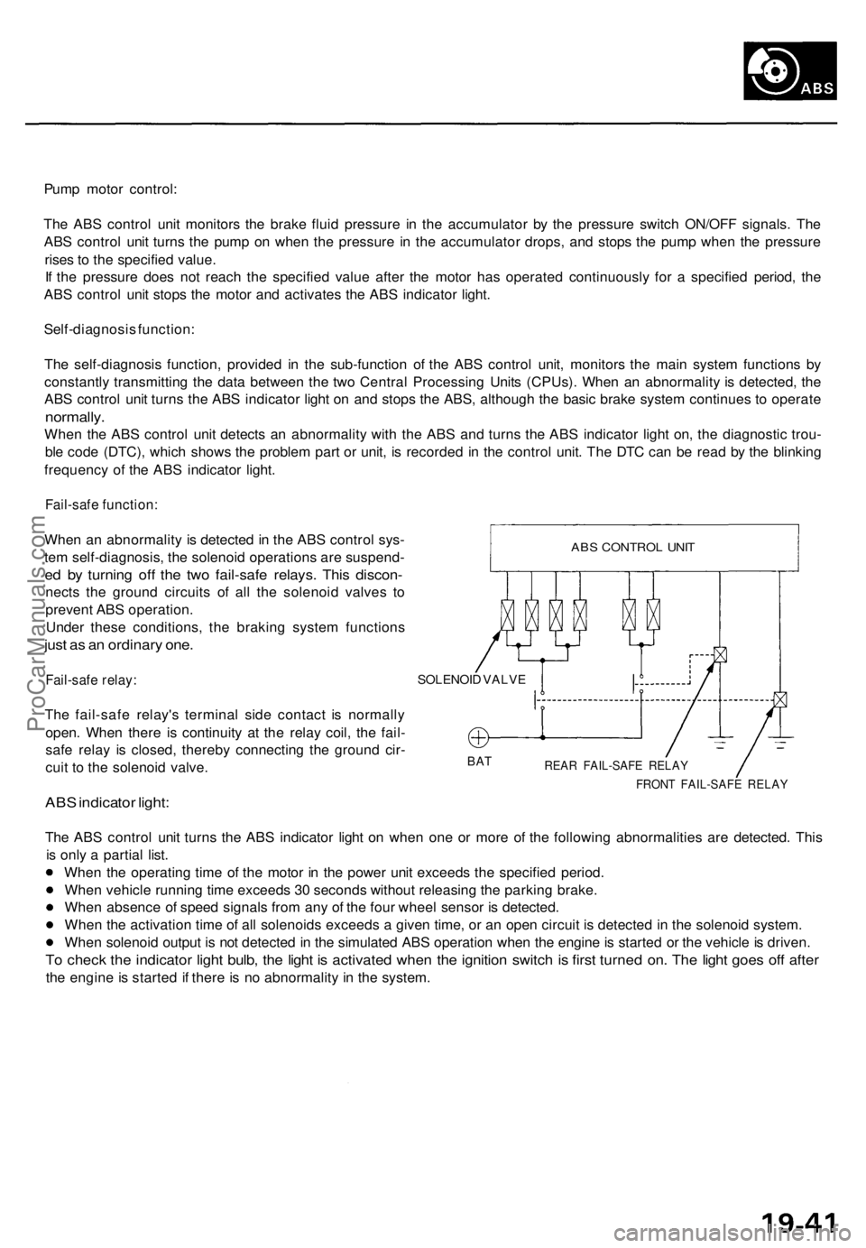
When an abnormality is detected in the ABS control sys-
tem self-diagnosis, the solenoid operations are suspend-
ed by turning off the two fail-safe relays. This discon-
nects the ground circuits of all the solenoid valves to
prevent ABS operation.
Under these conditions, the braking system functions
just as an ordinary one.
Fail-safe relay:
The fail-safe relay's terminal side contact is normally
open. When there is continuity at the relay coil, the fail-
safe relay is closed, thereby connecting the ground cir-
cuit to the solenoid valve.
ABS indicator light:
SOLENOID VALVE
BAT
REAR FAIL-SAFE RELAY
FRONT FAIL-SAFE RELAY
The ABS control unit turns the ABS indicator light on when one or more of the following abnormalities are detected. This
is only a partial list.
When the operating time of the motor in the power unit exceeds the specified period.
When vehicle running time exceeds 30 seconds without releasing the parking brake.
When absence of speed signals from any of the four wheel sensor is detected.
When the activation time of all solenoids exceeds a given time, or an open circuit is detected in the solenoid system.
When solenoid output is not detected in the simulated ABS operation when the engine is started or the vehicle is driven.
To check the indicator light bulb, the light is activated when the ignition switch is first turned on. The light goes off after
the engine is started if there is no abnormality in the system.
ABS CONTROL UNITProCarManuals.com