1995 ACURA TL check transmission fluid
[x] Cancel search: check transmission fluidPage 257 of 1771
Description
The automatic transmission is a combination of a 3-element torque converter and a dual-shaft electronically controlled
automatic transmission which provides 4 speeds forward and 1 reverse. The entire unit is positioned in line with the engine.
Torque Converter, Gears and Clutches
The torque converter consists of a pump, turbine, and stator, assembled in a single unit. They are connected to the engine
crankshaft so they turn together as a unit as the engine turns. Around the outside of the drive plate is a ring gear which
meshes with the starter pinion when the engine is being started.
The entire torque converter assembly serves as a flywheel while transmitting power to the transmission mainshaft.
The transmission has two parallel shafts: the mainshaft and the countershaft. The mainshaft is in line with the engine
crankshaft. The mainshaft includes the 1st, 4th and 2nd clutches and gears for 4th, 1st, 2nd and reverse (3rd gear is integral
with the mainshaft). The countershaft includes the 3rd, 1st-hold and reverse clutches, and gears for 3rd, 4th, 1st, 2nd,
reverse and parking. The secondary drive gear is integrated with the countershaft. The gears on the mainshaft are in con-
stant mesh with those on the countershaft. When certain combinations of gears in the transmission are engaged by clutch-
positions.
and
es, power is transmitted from the mainshaft to the countershaft to provide
Electronic Control
The electronic control system consists of a Powertrain Control Module (PCM), sensors, a linear solenoid and four solenoid
valves. Shifting and lock-up are electronically controlled for comfortable driving under all conditions.
The PCM is located below the dashboard, under the front lower panel on the passenger's side.
Hydraulic Control
The lower valve body assembly includes the main valve body, the secondary valve body, the throttle valve body, the lin-
ear solenoid, the shift control solenoid valves and the ATF passage body. They are bolted on the lower part of the trans-
mission housing. The regulator valve body, the ATF pump body, and the accumulator body are bolted to the torque con-
verter housing.
The main valve body on '96 model contains the manual valve, the 1-2 shift valve, the 2-3 shift valve, the 3-4 shift valve, the
4-3 kick-down valve and the Clutch Pressure Control (CPC) valve. The main valve body on '97 model contains the manual
valve, the 1-2 shift valve, the 2-3 shift valve, the 3-4 shift valve, the 4-3 kick-down valve and the main orifice control valve.
The secondary valve body on '96 model contains the 3-4 orifice control valve, the 4-3 shift timing valve, the modulator valve
and the accumulator pistons.The secondary valve body on '97 model contains the 3-4 orifice control valve, the 4-3 shift tim-
ing valve, the line pressure control valve, the modulator valve and the accumulator pistons. The throttle valve body
includes the throttle valve which is bolted onto the secondary valve body. The linear solenoid is joined to the throttle valve
body. The regulator valve body contains the regulator valve, the lock-up shift valve and the cooler relief valve. Fluid from
the regulator passes through the manual valve to the various control valves. The ATF pump body contains the lock-up tim-
ing valve, the lock-up control valve and the relief valve. The torque converter check valve is located in the torque converter
housing under the ATF pump body. The accumulator body contains the accumulator pistons. The reverse accumulator and
the 1st-hold accumulator pistons are assembled in the rear cover.
The 1st, 1st-hold, 2nd and reverse clutches receive fluid from their respective feed pipes, and the 3rd and 4th clutches
receive fluid from the internal hydraulic circuit.
Shift Control Mechanism
Input from various sensors located throughout the vehicle determines which shift control solenoid valve the PCM will acti-
vate. Activating a shift control solenoid valve changes modulator pressure, causing a shift valve to move. This pressurizes a
line to one of the clutches, engaging the clutch and its corresponding gear.
er through a fluid passage, causing the lock-up piston to be held against the torque converter cover. As this takes place, the
mainshaft rotates at the same speed as the engine crankshaft. Together with hydraulic control, the PCM optimizes the tim-
ing of the lock-up mechanism. The lock-up valves control the range of lock-up according to lock-up control solenoid valves
A and B, and throttle valve. When lock-up control solenoid valves A and B activate, modulator pressure changes. The lock-
up control solenoid valves A and B are mounted on the torque converter housing, and are controlled by the PCM.
(cont'd)
Lock-up Mechanism
In
position, in 2nd, 3rd, and 4th, and
position in 3rd, pressurized fluid is drained from the back of the torque convert-ProCarManuals.com
Page 284 of 1771
Position
(cont'd)
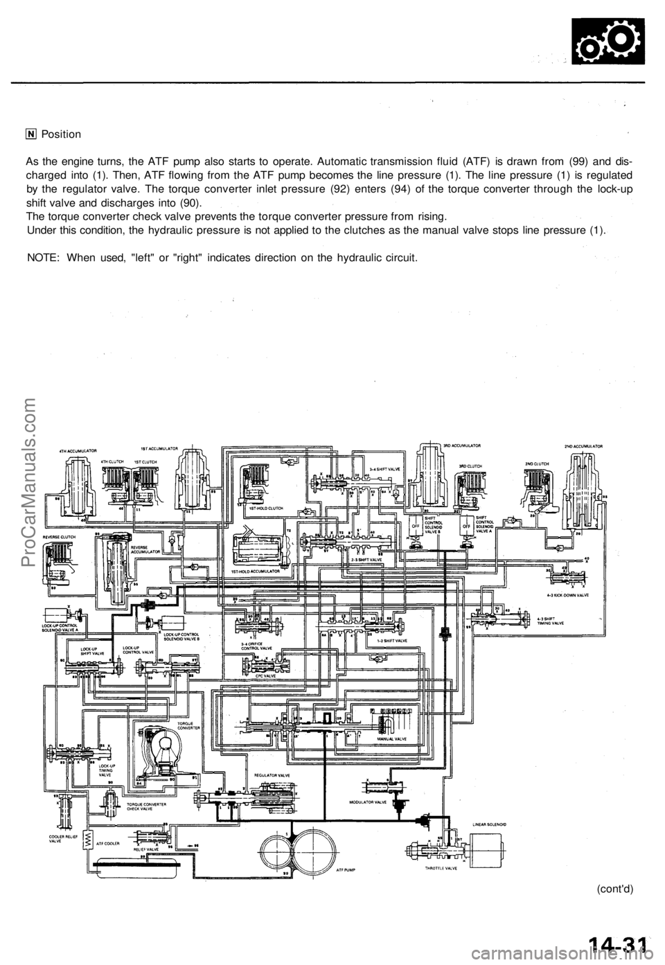
As the engine turns, the ATF pump also starts to operate. Automatic transmission fluid (ATF) is drawn from (99) and dis-
charged into (1). Then, ATF flowing from the ATF pump becomes the line pressure (1). The line pressure (1) is regulated
by the regulator valve. The torque converter inlet pressure (92) enters (94) of the torque converter through the lock-up
shift valve and discharges into (90).
The torque converter check valve prevents the torque converter pressure from rising.
Under this condition, the hydraulic pressure is not applied to the clutches as the manual valve stops line pressure (1).
NOTE: When used, "left" or "right" indicates direction on the hydraulic circuit.ProCarManuals.com
Page 328 of 1771
Fluid Level
Checking/Changing
Checking
NOTE: Check the fluid level with the engine at normal
operating temperature (the radiator fan comes on).
1. Park the vehicle on level ground. Turn off the
engine.
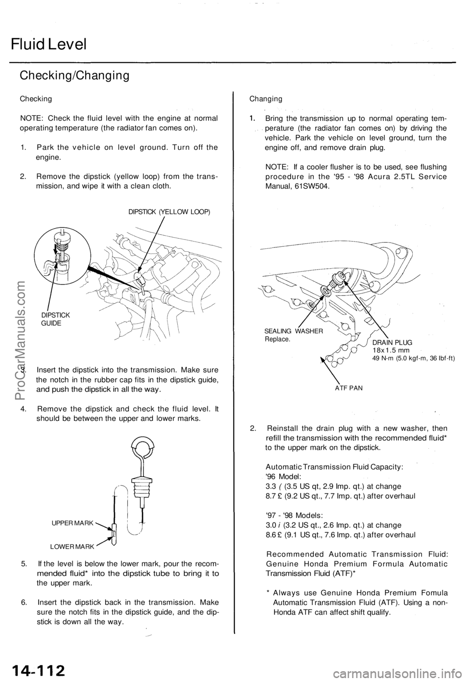
2. Remove the dipstick (yellow loop) from the trans-
mission, and wipe it with a clean cloth.
DIPSTICK (YELLOW LOOP)
DIPSTICK
GUIDE
3. Insert the dipstick into the transmission. Make sure
the notch in the rubber cap fits in the dipstick guide,
and push the dipstick in all the way.
4. Remove the dipstick and check the fluid level. It
should be between the upper and lower marks.
UPPER MARK
LOWER MARK
5. If the level is below the lower mark, pour the recom-
mended fluid* into the dipstick tube to bring it to
the upper mark.
6. Insert the dipstick back in the transmission. Make
sure the notch fits in the dipstick guide, and the dip-
stick is down all the way.
Changing
Bring the transmission up to normal operating tem-
perature (the radiator fan comes on) by driving the
vehicle. Park the vehicle on level ground, turn the
engine off, and remove drain plug.
NOTE: If a cooler flusher is to be used, see flushing
procedure in the '95 - '98 Acura 2.5TL Service
Manual, 61SW504.
SEALING WASHER
Replace.
DRAIN PLUG
18x1.5 mm
49 N-m (5.0 kgf-m, 36 Ibf-ft)
ATF PAN
2. Reinstall the drain plug with a new washer, then
refill the transmission with the recommended fluid*
to the upper mark on the dipstick.
Automatic Transmission Fluid Capacity:
'96 Model:
3.3 ( (3.5 US qt, 2.9 Imp. qt.) at change
8.7 £ (9.2 US qt., 7.7 Imp. qt.) after overhaul
'97 - '98 Models:
3.0 i (3.2 US qt., 2.6 Imp. qt.) at change
8.6 £ (9.1 US qt., 7.6 Imp. qt.) after overhaul
Recommended Automatic Transmission Fluid:
Genuine Honda Premium Formula Automatic
Transmission Fluid (ATF)*
* Always use Genuine Honda Premium Fomula
Automatic Transmission Fluid (ATF). Using a non-
Honda ATF can affect shift qualify.ProCarManuals.com
Page 334 of 1771
![ACURA TL 1995 Service Repair Manual
6. Disconnect the transmission sub-harness connector (14P).
7. Start the engine, and run it at 2,000 rpm.
TRANSMISSION SUB-HARNESS
CONNECTOR (14P)
8. Shift to the [HI or [P] position, and measure ACURA TL 1995 Service Repair Manual
6. Disconnect the transmission sub-harness connector (14P).
7. Start the engine, and run it at 2,000 rpm.
TRANSMISSION SUB-HARNESS
CONNECTOR (14P)
8. Shift to the [HI or [P] position, and measure](/manual-img/32/56993/w960_56993-333.png)
6. Disconnect the transmission sub-harness connector (14P).
7. Start the engine, and run it at 2,000 rpm.
TRANSMISSION SUB-HARNESS
CONNECTOR (14P)
8. Shift to the [HI or [P] position, and measure line pressure at fully-opened throttle.
9. Connect battery voltage to the linear solenoid terminals of the transmission sub-harness connector as shown.
10. Measure line pressure at fully-closed throttle.
If line pressure is out of specification, check and repair the probable cause in the table below.
PRESSURE
Line
SHIFT LEVER
POSITION
or
SYMPTOM
No (or
low)
line pressure
PROBABLE CAUSE
Torque converter,
ATF pump, pres-
sure regulator.
torque converter
check valve
FLUID PRESSURE
Standard
520 kPa
(5.3 kgf/cm2, 75 psi)
Fully closed throttle
|
910 kPa
(9.3 kgf/cm2, 130 psi)
Fully opened throttle
Service Limit
500 kPa
(5.1 kgf/cm2, 73 psi)
Fully closed throttle
790 kPa
(8.1 kgf/cm2, 120 psi)
Fully opened throttle
11. Stop the engine, and connect the transmission sub-harness connector (14P).
12. Disconnect the special tool from line pressure inspection hole, and connect the special tool to each inspection hole.
13. Start the engine, and run it at 2,000 rpm.
(cont'd)ProCarManuals.com
Page 936 of 1771

Description
The automatic transmission is a combination of a 3-element torque converter and a dual-shaft electronically controlled
automatic transmission which provides 4 speeds forward and 1 reverse. The entire unit is positioned in line with the engine.
Torque Converter, Gears and Clutches
The torque converter consists of a pump, turbine and stator, assembled in a single unit.
They are connected to the engine crankshaft so they turn together as a unit as the engine turns.
Around the outside of the drive plate is a ring gear which meshes with the starter pinion when the engine is being started.
The entire torque converter assembly serves as a flywheel while transmitting power to the transmission mainshaft.
The transmission has two parallel shafts: the mainshaft and the countershaft. The mainshaft is in line with the engine
crankshaft.
The mainshaft includes the 1st, 2nd and 4th clutches, and gears for 4th, 2nd, 1st and reverse (3rd gear is integral with the
mainshaft, while the reverse gear is integral with 4th gear).
The countershaft includes the 3rd, and 1st-hold clutches, and gears for 3rd, 4th, 1st, 2nd, reverse, and parking. The sec-
ondary drive gear is integrated with the countershaft.
The gears on the mainshaft are in constant mesh with those on the countershaft.
When certain combinations of gears in the transmission are engaged by clutches, power is transmitted from the mainshaft
to the countershaft to provide and positions.
Electronic Control
The electronic control system consists of the Transmission Control Module (TCM), sensors, a linear solenoid and four
solenoid valves. Shifting and lock-up are electronically controlled for comfortable driving under all conditions.
The TCM is located below the dashboard, behind the glove box on the passenger's side.
Hydraulic Control
The lower valve body assembly includes the main valve body, the servo body and the shift control solenoid valves. They
are bolted on the lower part of the transmission housing.
Other valve bodies, the regulator valve body, the ATF pump body, the 2nd accumulator body, and the throttle valve body,
are bolted to the torque converter housing.
The main valve body contains the manual valve, the 1 - 2 shift valve, the 2 - 3 shift valve, the 3 - 4 shift valve, the 4th kick-
down valve, the 2 - 3 orifice control valve, the 3 - 4 orifice control valve, the 4th exhaust valve, the servo control valve,
and the main orifice control valve.
The servo body contains the servo valve, 3rd and 4th accumulator pistons.
The regulator valve body contains the regulator valve, the lock-up shift valve, and the cooler relief valve.
Fluid from the regulator passes through the manual valve to the various control valves.
The throttle valve body includes the throttle valve which is bolted onto the 2nd accumulator body. The 2nd accumulator
piston is assembled in the 2nd accumulator body.
The linear solenoid is joined with the throttle valve body.
The ATF pump body contains the modulator valve, the lock-up control valve, the lock-up timing valve, and the relief valve.
The torque converter check valve is located in the torque converter housing under the ATF pump body.
The 1st and 1st-hold accumulator pistons are assembled in the rear cover.
The clutches receive fluid from their respective feed pipes or internal hydraulic circuit.
Shift Control Mechanism
Input from various sensors located throughout the vehicle determines which shift control solenoid valve the TCM will acti-
vate. Activating a shift control solenoid valve changes modulator pressure, causing a shift valve to move. This pressurizes
a line to one of the clutches, engaging that clutch and its corresponding gear.
Lock-up Mechanism
In position, in 2nd, 3rd and 4th, and in position in 3rd, pressurized fluid is drained from the back of the torque con-
verter through a fluid passage, causing the lock-up piston to be held against the torque converter cover. As this takes place,
the mainshaft rotates at the same speed as the engine crankshaft. Together with hydraulic control, the TCM optimizes the
timing of the lock-up mechanism. The lock-up valves control the range of lock-up according to lock-up control solenoid
valves A and B, and throttle valve. When lock-up control solenoid valves A and B activate, the modulator pressure changes.
The lock-up control solenoid valves A and B are mounted on the torque converter housing, and are controlled by the TCM.ProCarManuals.com
Page 962 of 1771
Description
Position
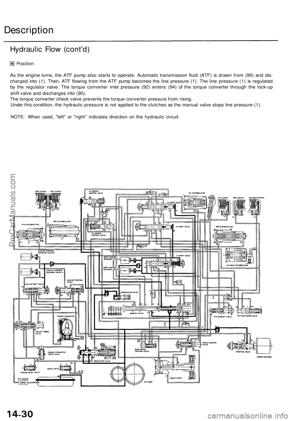
As the engine turns, the ATF pump also starts to operate. Automatic transmission fluid (ATF) is drawn from (99) and dis-
charged into (1). Then, ATF flowing from the ATF pump becomes the line pressure (1). The line pressure (1) is regulated
by the regulator valve. The torque converter inlet pressure (92) enters (94) of the torque converter through the lock-up
shift valve and discharges into (90).
The torque converter check valve prevents the torque converter pressure from rising.
Under this condition, the hydraulic pressure is not applied to the clutches as the manual valve stops line pressure (1).
NOTE: When used, "left" or "right" indicates direction on the hydraulic circuit.
Hydraulic Flow (cont'd)ProCarManuals.com
Page 996 of 1771
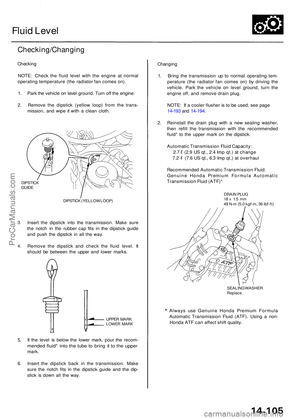
Fluid Leve l
Checking/Changin g
Checking
NOTE : Chec k th e flui d leve l wit h th e engin e a t norma l
operatin g temperatur e (th e radiato r fa n come s on) .
1 . Par k th e vehicl e o n leve l ground . Tur n of f th e engine .
2 . Remov e th e dipstic k (yello w loop ) fro m th e trans -
mission , an d wip e i t wit h a clea n cloth .
DIPSTIC KGUIDE
3.
4 .
DIPSTIC K (YELLO W LOOP )
Insert th e dipstic k int o th e transmission . Mak e sur e
th e notc h i n th e rubbe r ca p fit s i n th e dipstic k guid e
an d pus h th e dipstic k i n al l th e way .
Remov e th e dipstic k an d chec k th e flui d level . I t
shoul d b e betwee n th e uppe r an d lowe r marks .
5.
6 .
UPPE R MAR KLOWE R MAR K
It th e leve l i s belo w th e lowe r mark , pou r th e recom -
mended fluid * int o th e tub e t o brin g i t t o th e uppe r
mark.
Inser t th e dipstic k bac k i n th e transmission . Mak e
sur e th e notc h fit s i n th e dipstic k guid e an d th e dip -
stic k i s dow n al l th e way . Changin
g
1 . Brin g th e transmissio n u p t o norma l operatin g tem -
peratur e (th e radiato r fa n come s on ) b y drivin g th e
vehicle . Par k th e vehicl e o n leve l ground , tur n th e
engin e off , an d remov e drai n plug .
NOTE : I f a coole r flushe r i s t o b e used , se e pag e
14-19 3 an d 14-194 .
2. Reinstal l th e drai n plu g wit h a ne w sealin g washer ,
the n refil l th e transmissio n wit h th e recommende d
fluid * t o th e uppe r mar k o n th e dipstick .
Automati c Transmissio n Flui d Capacity :
2. 7 (2. 9 U S qt. , 2. 4 Im p qt. ) a t chang e
7.2 (7. 6 U S qt. , 6. 3 Im p qt. ) a t overhau l
Recommende d Automati c Transmissio n Fluid :
Genuin e Hond a Premiu m Formul a Automati c
Transmissio n Flui d (ATF) *
DRAIN PLU G18 x 1. 5 m m49 N- m (5. 0 kgf-m , 3 6 Ibf-ft )
SEALIN G WASHE R
Replace .
Always us e Genuin e Hond a Premiu m Formul a
Automati c Transmissio n Flui d (ATF) . Usin g a non -
Hond a AT F ca n affec t shif t quality .
ProCarManuals.com