1995 ACURA TL check engine
[x] Cancel search: check enginePage 53 of 1771
59. Raise the hoist.
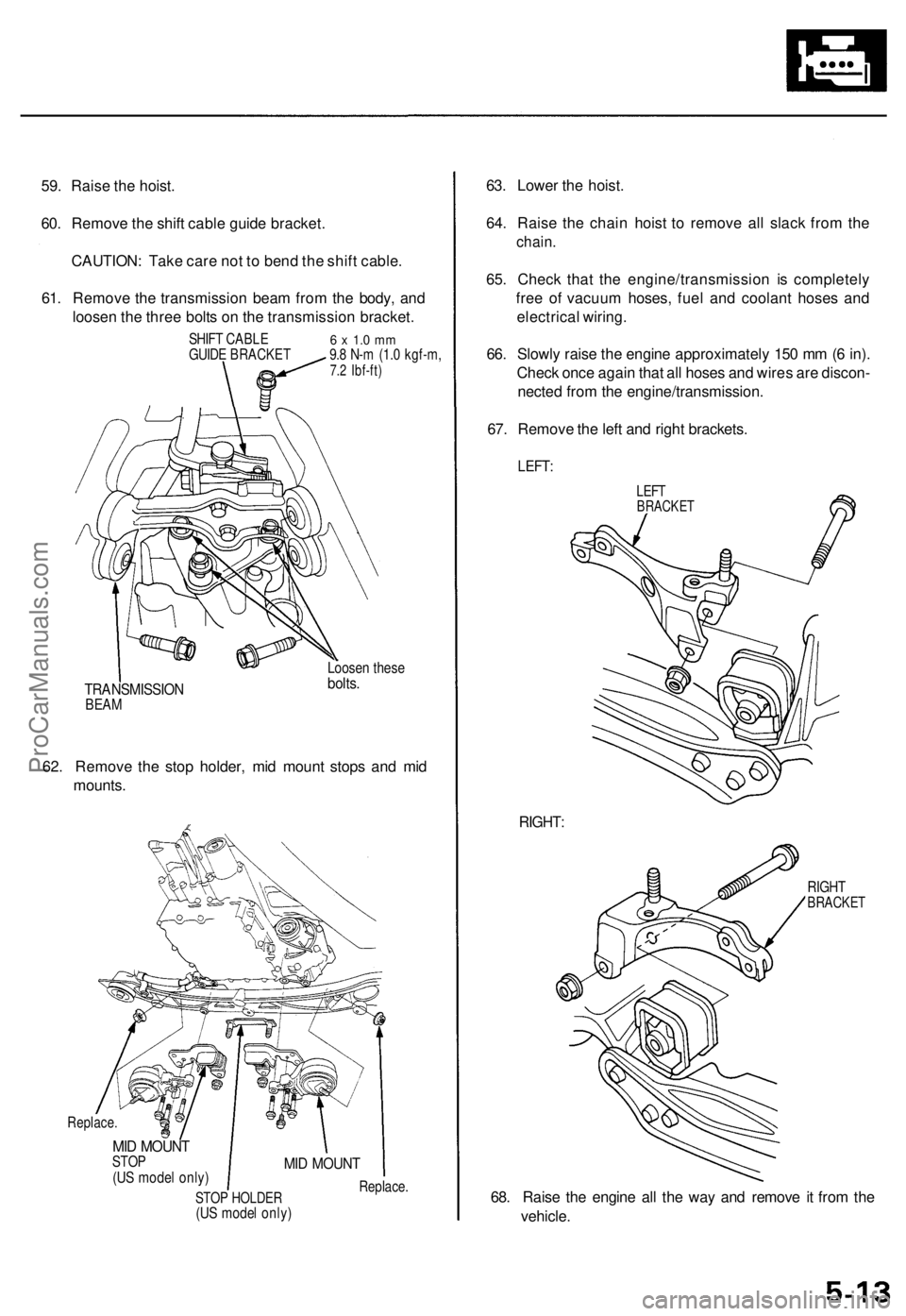
60. Remove the shift cable guide bracket.
CAUTION: Take care not to bend the shift cable.
61. Remove the transmission beam from the body, and
loosen the three bolts on the transmission bracket.
SHIFT CABLE
GUIDE BRACKET
6 x 1.0 mm
9.8 N-m (1.0 kgf-m,
7.2 Ibf-ft)
TRANSMISSION
BEAM
Loosen these
bolts.
62. Remove the stop holder, mid mount stops and mid
mounts.
Replace.
MID MOUNT
STOP
(US model only)
STOP HOLDER
(US model only)
MID MOUNT
Replace.
63. Lower the hoist.
64. Raise the chain hoist to remove all slack from the
chain.
65. Check that the engine/transmission is completely
free of vacuum hoses, fuel and coolant hoses and
electrical wiring.
66. Slowly raise the engine approximately 150 mm (6 in).
Check once again that all hoses and wires are discon-
nected from the engine/transmission.
67. Remove the left and right brackets.
LEFT:
LEFT
BRACKET
RIGHT:
RIGHT
BRACKET
68. Raise the engine all the way and remove it from the
vehicle.ProCarManuals.com
Page 57 of 1771
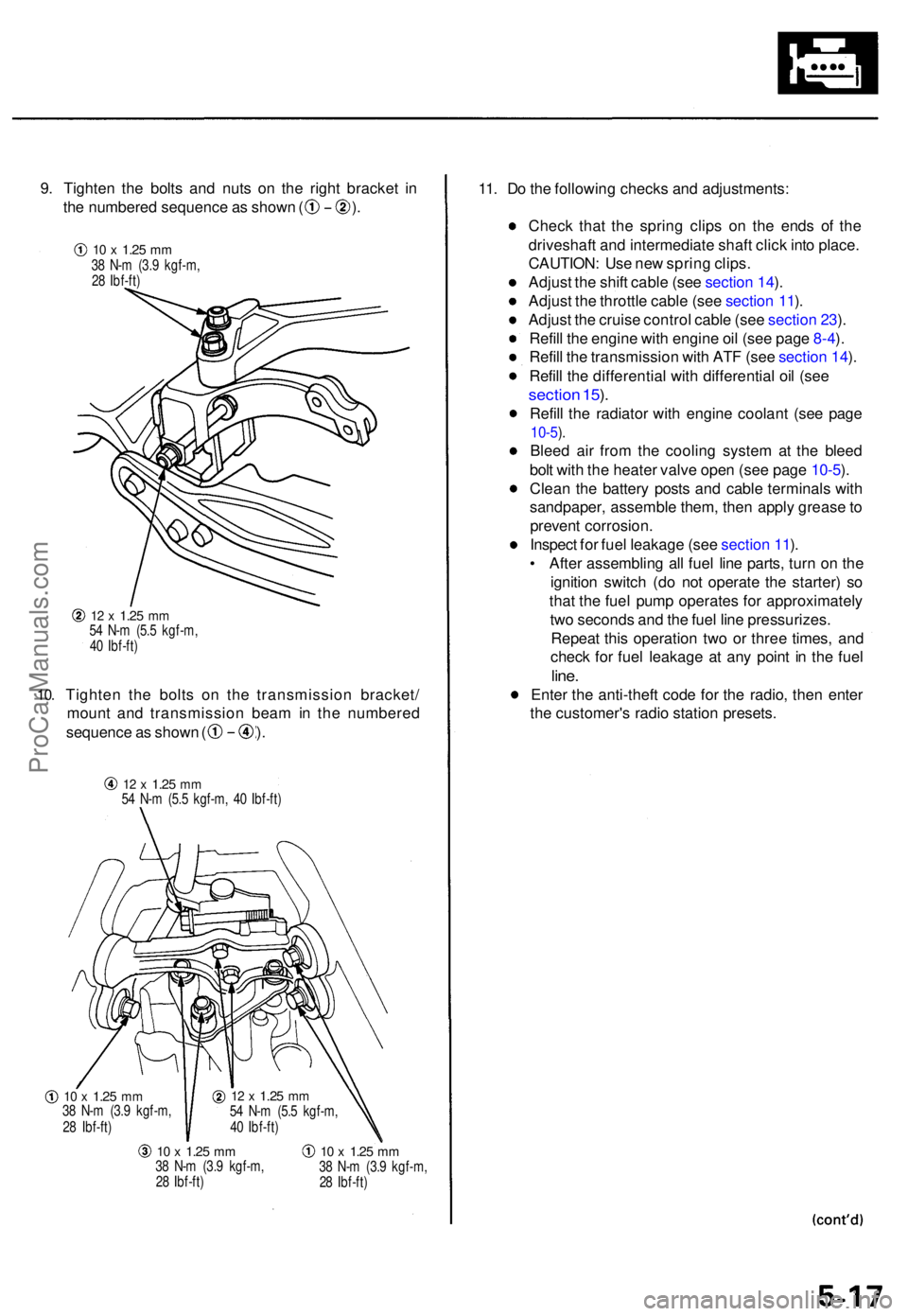
9. Tighte n th e bolt s an d nut s o n th e righ t bracke t i n
th e numbere d sequenc e a s show n ( ) .
10.
12 x 1.2 5 mm54 N- m (5. 5 kgf-m ,
4 0 Ibf-ft )
Tighte n th e bolt s o n th e transmissio n bracket /
moun t an d transmissio n bea m in th e numbere d
sequence a s show n ( ) .
12 x 1.2 5 mm54 N- m (5. 5 kgf-m , 4 0 Ibf-ft )
10 x 1.2 5 mm38 N- m (3. 9 kgf-m ,
2 8 Ibf-ft )
10 x 1.2 5 mm38 N- m (3. 9 kgf-m ,
2 8 Ibf-ft )10 x 1.2 5 mm38 N- m (3. 9 kgf-m ,
2 8 Ibf-ft )
11. D o th e followin g check s an d adjustments :
Chec k tha t th e sprin g clip s o n th e end s o f th e
driveshaf t an d intermediat e shaf t clic k int o place .
CAUTION : Us e ne w sprin g clips .
Adjus t th e shif t cabl e (se e sectio n 14 ).
Adjus t th e throttl e cabl e (se e sectio n 11 ).
Adjus t th e cruis e contro l cabl e (se e sectio n 23 ).
Refil l th e engine with engin e oi l (se e pag e 8-4 ).
Refil l th e transmissio n wit h AT F (se e sectio n 14 ).
Refil l th e differentia l wit h differentia l oi l (se e
sectio n 15 ).
Refil l th e radiato r wit h engine coolant (se e pag e
10-5).
Blee d ai r fro m th e coolin g syste m a t th e blee d
bol t wit h th e heate r valv e ope n (se e pag e 10-5 ).
Clea n th e batter y post s an d cabl e terminal s wit h
sandpaper , assembl e them , the n appl y greas e to
preven t corrosion .
Inspec t fo r fue l leakag e (se e sectio n 11 ).
• Afte r assemblin g al l fue l lin e parts , tur n o n th e
ignitio n switc h (d o no t operat e th e starter ) s o
tha t th e fue l pum p operates for approximatel y
tw o second s an d th e fue l lin e pressurizes .
Repea t thi s operatio n tw o o r thre e times , an d
chec k fo r fue l leakag e a t an y poin t i n th e fue l
line.
Ente r th e anti-thef t cod e fo r th e radio , the n ente r
th e customer' s radi o statio n presets .
12 x 1.2 5 mm54 N- m (5. 5 kgf-m ,
4 0 Ibf-ft )
10 x 1.2 5 mm38 N- m (3. 9 kgf-m ,
2 8 Ibf-ft )
ProCarManuals.com
Page 94 of 1771
Hydraulic Tappets
Valve Installation
When installing valves in the cylinder head, coat the
valve stems with oil before inserting them into the valve
guides. Make sure the valves move up and down
smoothly.
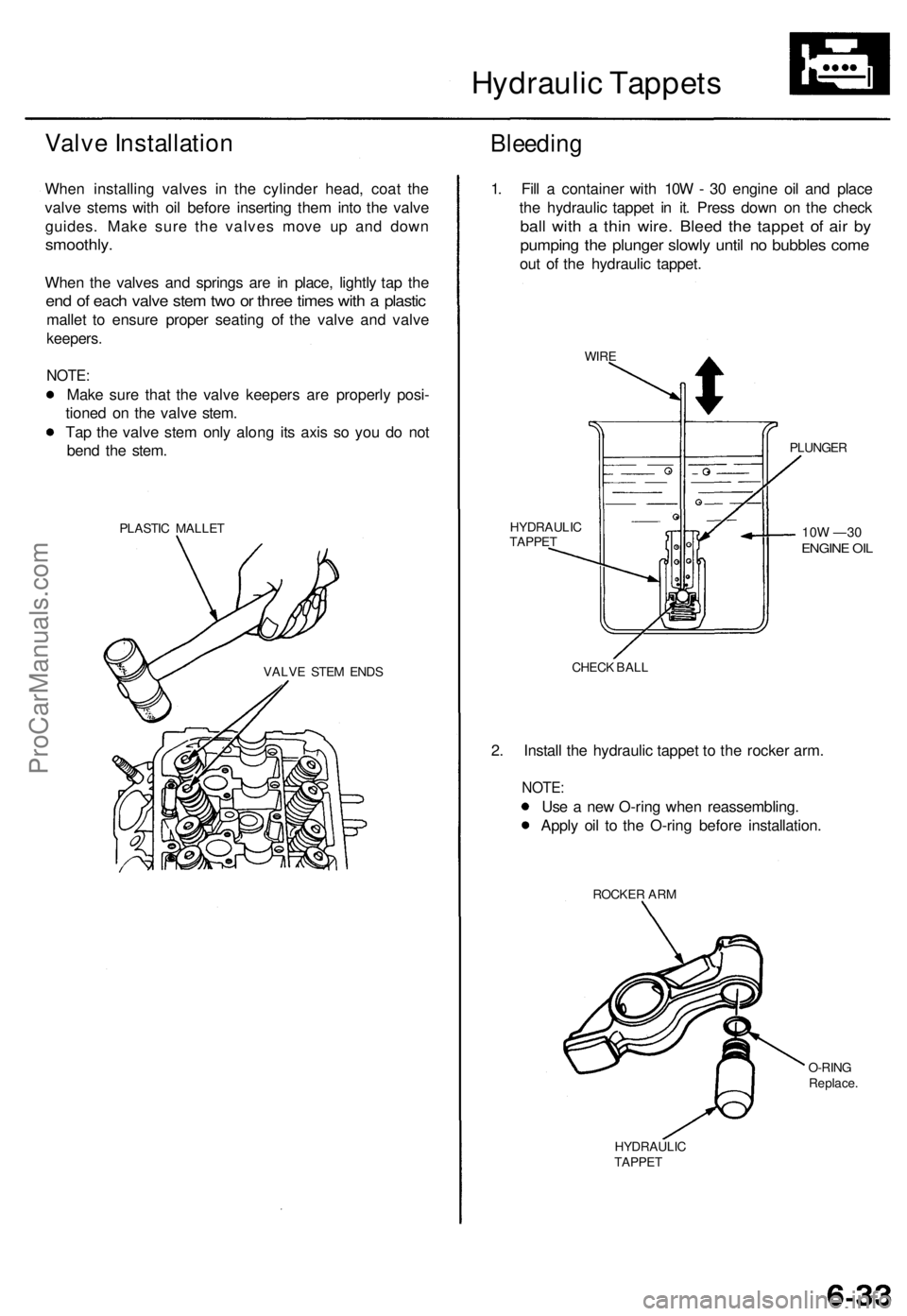
When the valves and springs are in place, lightly tap the
end of each valve stem two or three times with a plastic
mallet to ensure proper seating of the valve and valve
keepers.
NOTE:
Make sure that the valve keepers are properly posi-
tioned on the valve stem.
Tap the valve stem only along its axis so you do not
bend the stem.
PLASTIC MALLET
Bleeding
VALVE STEM ENDS
1. Fill a container with 10W - 30 engine oil and place
the hydraulic tappet in it. Press down on the check
ball with a thin wire. Bleed the tappet of air by
pumping the plunger slowly until no bubbles come
out of the hydraulic tappet.
WIRE
PLUNGER
10W —30
ENGINE OIL
HYDRAULIC
TAPPET
CHECK BALL
2. Install the hydraulic tappet to the rocker arm.
NOTE:
Use a new O-ring when reassembling.
Apply oil to the O-ring before installation.
ROCKER ARM
O-RING
Replace.
HYDRAULIC
TAPPETProCarManuals.com
Page 97 of 1771
Cylinder Heads
Installation (cont'd)
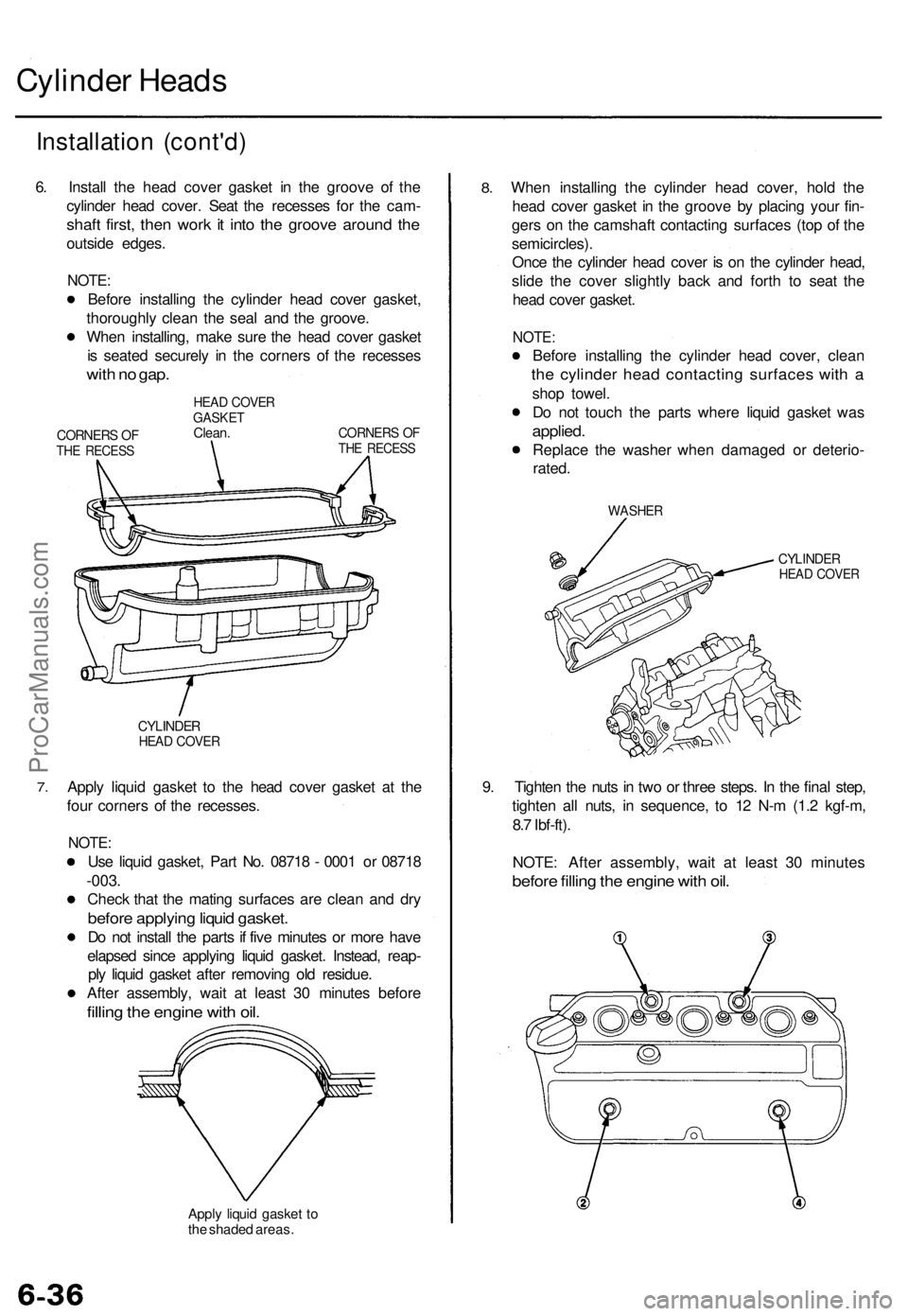
6. Install the head cover gasket in the groove of the
cylinder head cover. Seat the recesses for the cam-
shaft first, then work it into the groove around the
outside edges.
NOTE:
Before installing the cylinder head cover gasket,
thoroughly clean the seal and the groove.
When installing, make sure the head cover gasket
is seated securely in the corners of the recesses
with no gap.
CORNERS OF
THE RECESS
HEAD COVER
GASKET
Clean.
CORNERS OF
THE RECESS
7.
CYLINDER
HEAD COVER
Apply liquid gasket to the head cover gasket at the
four corners of the recesses.
NOTE:
Use liquid gasket, Part No. 08718 - 0001 or 08718
-003.
Check that the mating surfaces are clean and dry
before applying liquid gasket.
Do not install the parts if five minutes or more have
elapsed since applying liquid gasket. Instead, reap-
ply liquid gasket after removing old residue.
After assembly, wait at least 30 minutes before
filling the engine with oil.
Apply liquid gasket to
the shaded areas.
8.
When installing the cylinder head cover, hold the
head cover gasket in the groove by placing your fin-
gers on the camshaft contacting surfaces (top of the
semicircles).
Once the cylinder head cover is on the cylinder head,
slide the cover slightly back and forth to seat the
head cover gasket.
NOTE:
Before installing the cylinder head cover, clean
the cylinder head contacting surfaces with a
shop towel.
Do not touch the parts where liquid gasket was
applied.
Replace the washer when damaged or deterio-
rated.
WASHER
CYLINDER
HEAD COVER
9. Tighten the nuts in two or three steps. In the final step,
tighten all nuts, in sequence, to 12 N-m (1.2 kgf-m,
8.7 Ibf-ft).
NOTE: After assembly, wait at least 30 minutes
before filling the engine with oil.ProCarManuals.com
Page 116 of 1771
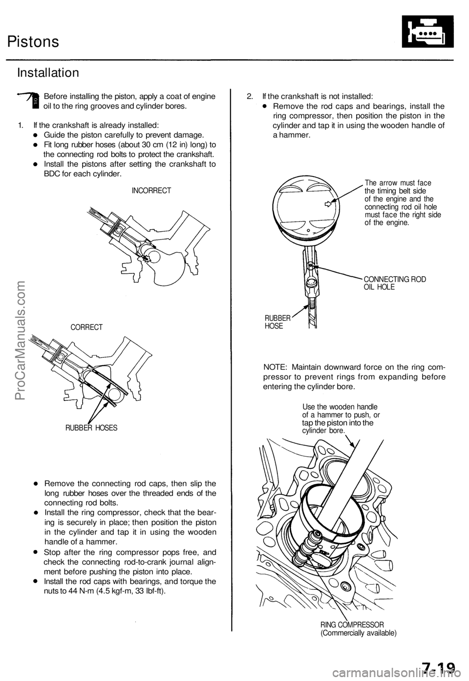
Pistons
Installation
Before installing the piston, apply a coat of engine
oil to the ring grooves and cylinder bores.
1. If the crankshaft is already installed:
Guide the piston carefully to prevent damage.
Fit long rubber hoses (about 30 cm (12 in) long) to
the connecting rod bolts to protect the crankshaft.
Install the pistons after setting the crankshaft to
BDC for each cylinder.
INCORRECT
CORRECT
RUBBER HOSES
Remove the connecting rod caps, then slip the
long rubber hoses over the threaded ends of the
connecting rod bolts.
Install the ring compressor, check that the bear-
ing is securely in place; then position the piston
in the cylinder and tap it in using the wooden
handle of a hammer.
Stop after the ring compressor pops free, and
check the connecting rod-to-crank journal align-
ment before pushing the piston into place.
Install the rod caps with bearings, and torque the
nuts to 44 N-m (4.5 kgf-m, 33 Ibf-ft).
2. If the crankshaft is not installed:
Remove the rod caps and bearings, install the
ring compressor, then position the piston in the
cylinder and tap it in using the wooden handle of
a hammer.
The arrow must face
the timing belt side
of the engine and the
connecting rod oil hole
must face the right side
of the engine.
CONNECTING ROD
OIL HOLE
RUBBER
HOSE
NOTE: Maintain downward force on the ring com-
pressor to prevent rings from expanding before
entering the cylinder bore.
Use the wooden handle
of a hammer to push, or
tap the piston into the
cylinder bore.
RING COMPRESSOR
(Commercially available)ProCarManuals.com
Page 120 of 1771
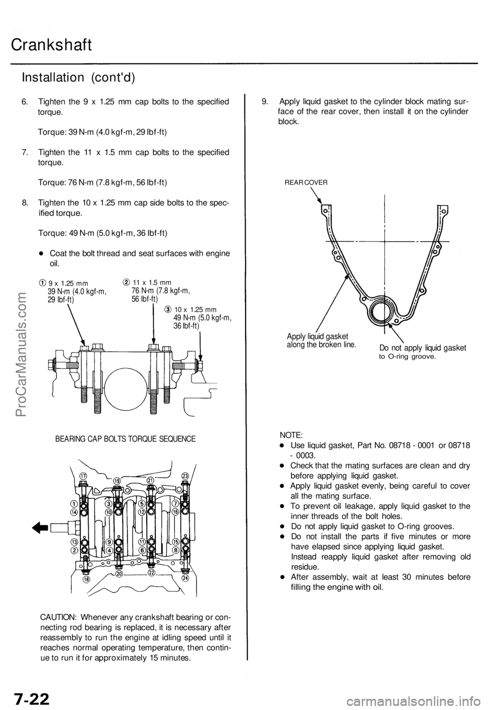
Crankshaft
BEARING CAP BOLTS TORQUE SEQUENCE
CAUTION: Whenever any crankshaft bearing or con-
necting rod bearing is replaced, it is necessary after
reassembly to run the engine at idling speed until it
reaches normal operating temperature, then contin-
ue to run it for approximately 15 minutes.
9. Apply liquid gasket to the cylinder block mating sur-
face of the rear cover, then install it on the cylinder
block.
REAR COVER
Apply liquid gasket
along the broken line.
Do not apply liquid gasket
to O-ring groove.
NOTE:
Use liquid gasket, Part No. 08718 - 0001 or 08718
- 0003.
Check that the mating surfaces are clean and dry
before applying liquid gasket.
Apply liquid gasket evenly, being careful to cover
all the mating surface.
To prevent oil leakage, apply liquid gasket to the
inner threads of the bolt holes.
Do not apply liquid gasket to O-ring grooves.
Do not install the parts if five minutes or more
have elapsed since applying liquid gasket.
Instead reapply liquid gasket after removing old
residue.
After assembly, wait at least 30 minutes before
filling the engine with oil.
Installation (cont'd)
6. Tighten the 9 x 1.25 mm cap bolts to the specified
torque.
Torque: 39 N-m (4.0 kgf-m, 29 Ibf-ft)
7. Tighten the 11 x 1.5 mm cap bolts to the specified
torque.
Torque: 76 N-m (7.8 kgf-m, 56 Ibf-ft)
8. Tighten the 10 x 1.25 mm cap side bolts to the spec-
ified torque.
Torque: 49 N-m (5.0 kgf-m, 36 Ibf-ft)
Coat the bolt thread and seat surfaces with engine
oil.
9 x
1.25
mm
39 N-m (4.0 kgf-m,
29 Ibf-ft)
11 x 1.5 mm
76 N-m (7.8 kgf-m,
56 Ibf-ft)
10 x
1.25
mm
49 N-m (5.0 kgf-m,
36 Ibf-ft)ProCarManuals.com
Page 126 of 1771
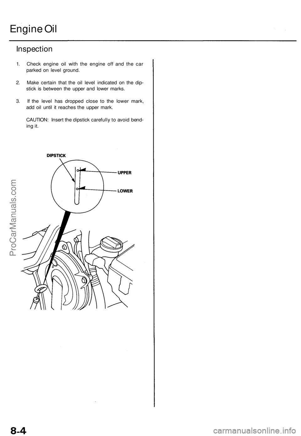
Inspection
1. Check engine oil with the engine off and the car
parked on level ground.
2. Make certain that the oil level indicated on the dip-
stick is between the upper and lower marks.
3. If the level has dropped close to the lower mark,
add oil until it reaches the upper mark.
CAUTION: Insert the dipstick carefully to avoid bend-
ing it.
Engine OilProCarManuals.com
Page 128 of 1771
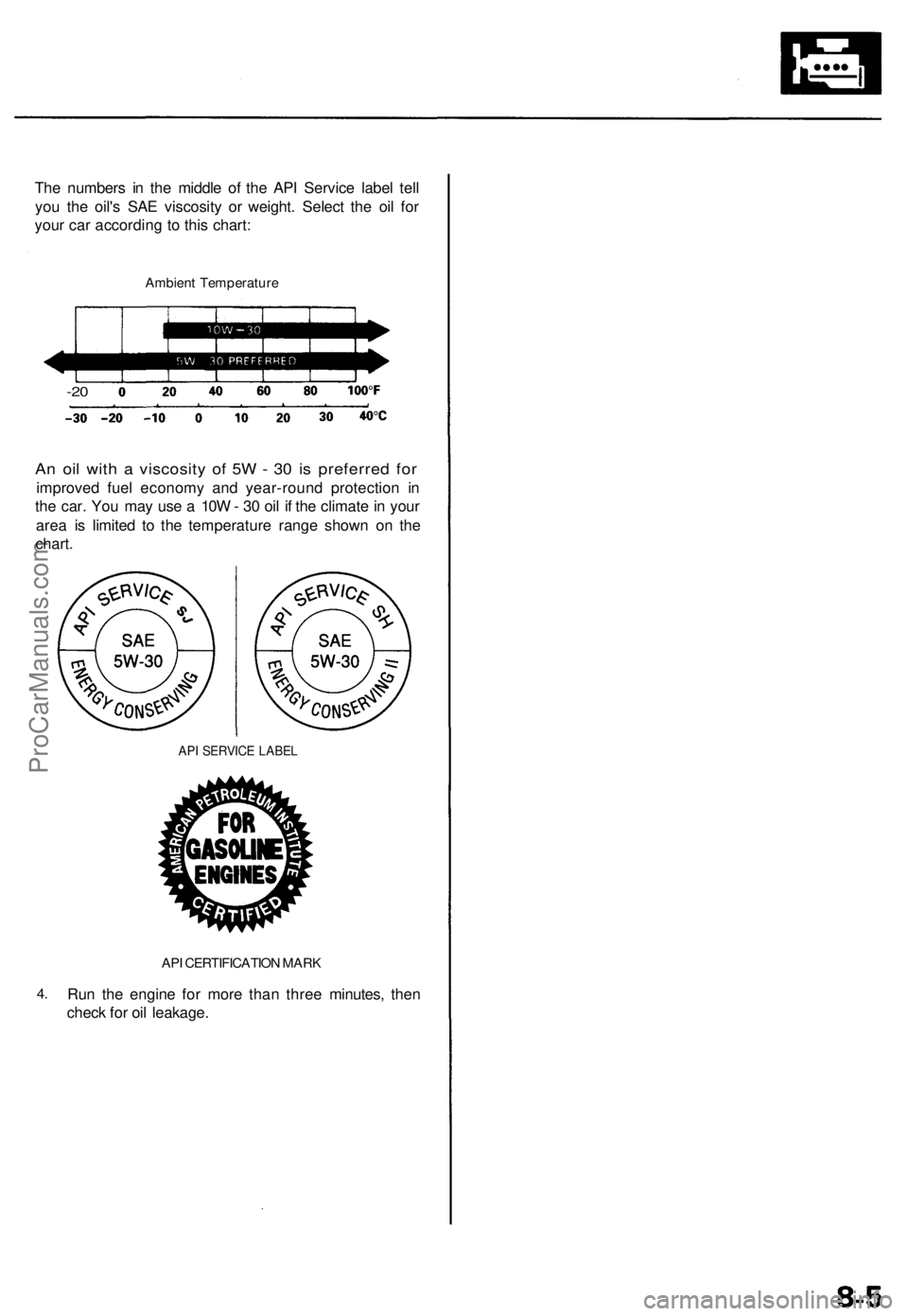
The numbers in the middle of the API Service label tell
you the oil's SAE viscosity or weight. Select the oil for
your car according to this chart:
Ambient Temperature
-20
An oil with a viscosity of 5W - 30 is preferred for
improved fuel economy and year-round protection in
the car. You may use a 10W - 30 oil if the climate in your
area is limited to the temperature range shown on the
chart.
API SERVICE LABEL
4.
API CERTIFICATION MARK
Run the engine for more than three minutes, then
check for oil leakage.ProCarManuals.com