1995 ACURA TL low beam
[x] Cancel search: low beamPage 53 of 1771
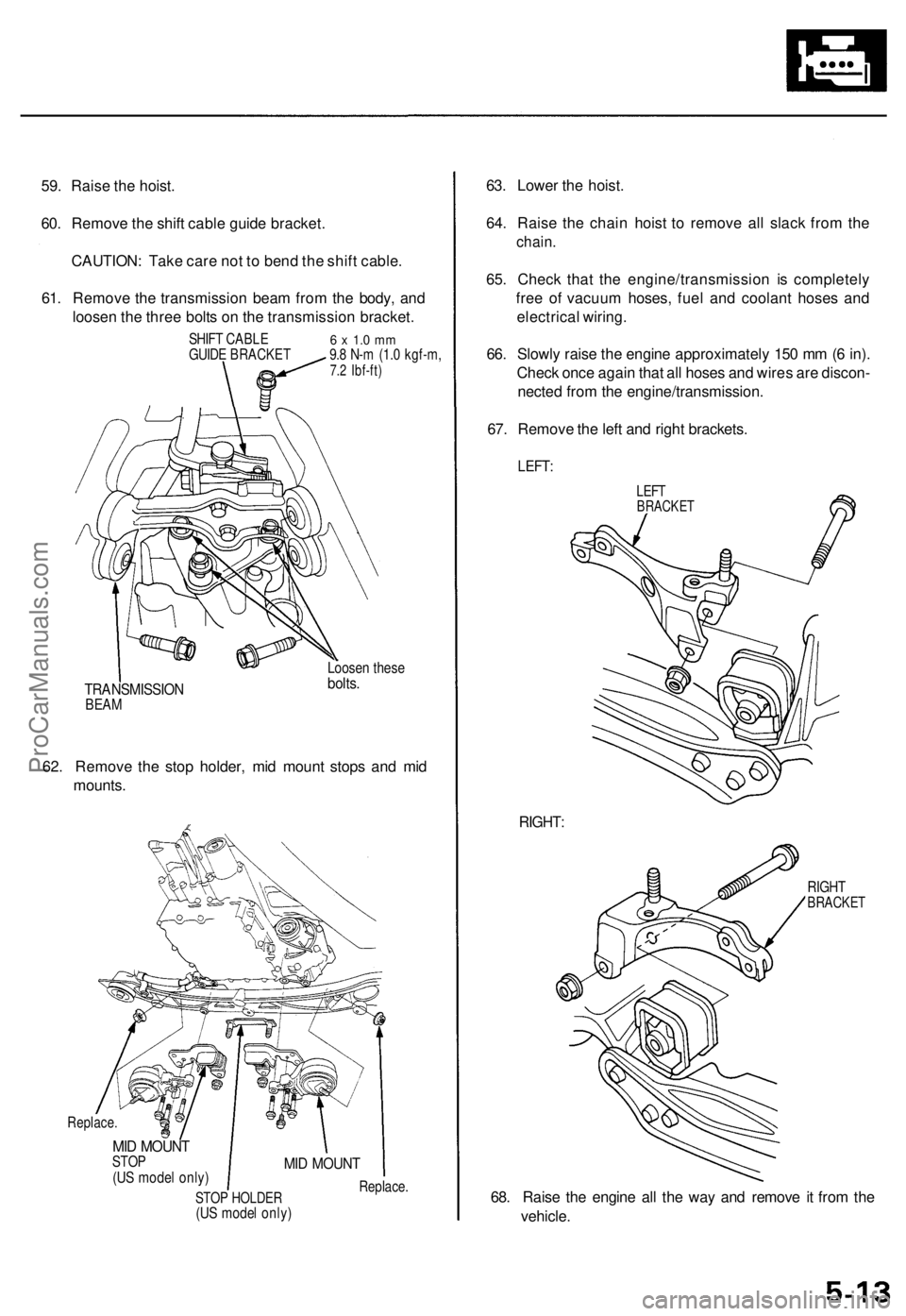
59. Raise the hoist.
60. Remove the shift cable guide bracket.
CAUTION: Take care not to bend the shift cable.
61. Remove the transmission beam from the body, and
loosen the three bolts on the transmission bracket.
SHIFT CABLE
GUIDE BRACKET
6 x 1.0 mm
9.8 N-m (1.0 kgf-m,
7.2 Ibf-ft)
TRANSMISSION
BEAM
Loosen these
bolts.
62. Remove the stop holder, mid mount stops and mid
mounts.
Replace.
MID MOUNT
STOP
(US model only)
STOP HOLDER
(US model only)
MID MOUNT
Replace.
63. Lower the hoist.
64. Raise the chain hoist to remove all slack from the
chain.
65. Check that the engine/transmission is completely
free of vacuum hoses, fuel and coolant hoses and
electrical wiring.
66. Slowly raise the engine approximately 150 mm (6 in).
Check once again that all hoses and wires are discon-
nected from the engine/transmission.
67. Remove the left and right brackets.
LEFT:
LEFT
BRACKET
RIGHT:
RIGHT
BRACKET
68. Raise the engine all the way and remove it from the
vehicle.ProCarManuals.com
Page 55 of 1771
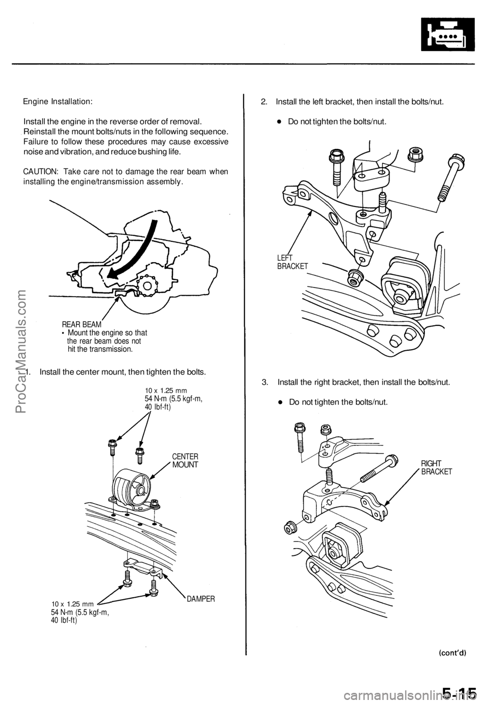
Engine Installation:
Install the engine in the reverse order of removal.
Reinstall the mount bolts/nuts in the following sequence.
Failure to follow these procedures may cause excessive
noise and vibration, and reduce bushing life.
CAUTION: Take care not to damage the rear beam when
installing the engine/transmission assembly.
REAR BEAM
Mount the engine so that
the rear beam does not
hit the transmission.
1. Install the center mount, then tighten the bolts.
10 x
1.25
mm
54 N-m (5.5 kgf-m,
40 Ibf-ft)
10 x
1.25
mm
54 N-m (5.5 kgf-m,
40 Ibf-ft)
CENTER
MOUNT
DAMPER
2. Install the left bracket, then install the bolts/nut.
Do not tighten the bolts/nut.
LEFT
BRACKET
3. Install the right bracket, then install the bolts/nut.
Do not tighten the bolts/nut.
RIGHT
BRACKETProCarManuals.com
Page 96 of 1771
Cylinder Heads
Installation
Install th e cylinde r head s in th e revers e orde r o f removal .
NOTE:
Alway s us e ne w cylinde r hea d gaskets .
Cylinde r head s an d cylinde r bloc k surfac e mus t b e
clean .
Turn th e camshaft s s o th e pulle y locatin g pi n hole s
are a t th e top .
Turn th e crankshaf t s o th e No . 1 pisto n is a t TD C (se e
pag e 6-8 ).
Clea n th e oi l contro l orifice s befor e installing .
D o no t us e th e uppe r an d lowe r cover s t o stor e
remove d item .
Clea n th e uppe r an d lowe r cover s befor e installation .
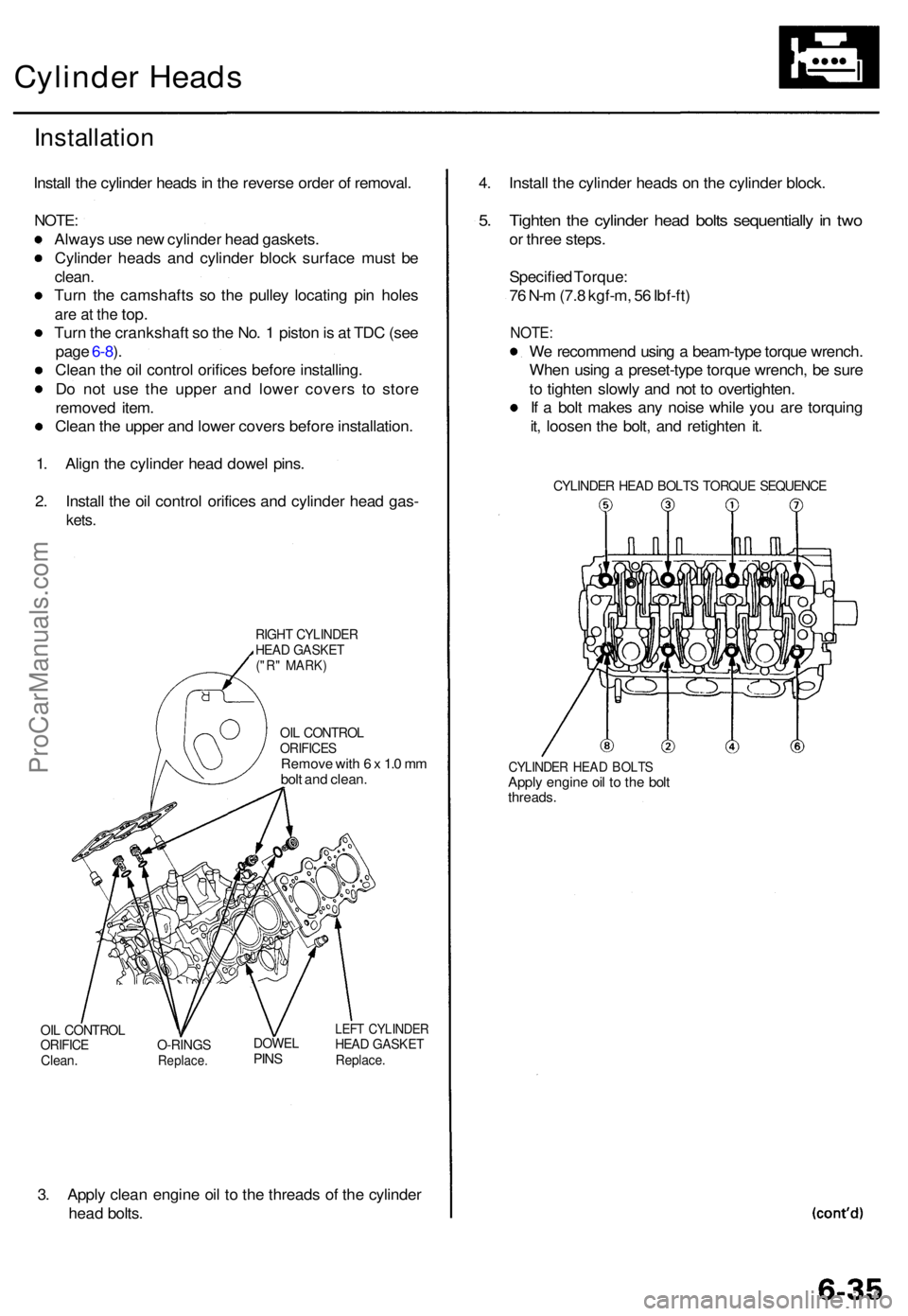
1 . Alig n th e cylinde r hea d dowe l pins .
2 . Instal l th e oi l contro l orifice s an d cylinde r hea d gas -
kets.
RIGH T CYLINDE RHEAD GASKE T("R" MARK )
OIL CONTRO LORIFICESRemove wit h 6 x 1. 0 m m
bol t an d clean .
OIL CONTRO LORIFICEClean.O-RING SReplace .
DOWELPINS
LEF T CYLINDE RHEAD GASKE TReplace.
3. Appl y clea n engin e oi l t o th e thread s o f th e cylinde r
hea d bolts . 4
. Instal l th e cylinde r head s o n th e cylinde r block .
5. Tighte n th e cylinde r hea d bolt s sequentiall y in tw o
or thre e steps .
Specifie d Torque :
7 6 N- m (7. 8 kgf-m , 5 6 Ibf-ft )
NOTE :
We recommen d usin g a beam-typ e torqu e wrench .
Whe n usin g a preset-typ e torqu e wrench , b e sur e
t o tighte n slowl y an d no t t o overtighten .
I f a bol t make s an y nois e whil e yo u ar e torquin g
it , loose n th e bolt , an d retighte n it .
CYLINDE R HEA D BOLT S TORQU E SEQUENC E
CYLINDER HEA D BOLT SApply engin e oi l t o th e bol tthreads .
ProCarManuals.com
Page 316 of 1771
Mainshaft/Countershaft Speed Sensors
Replacement (cont'd)
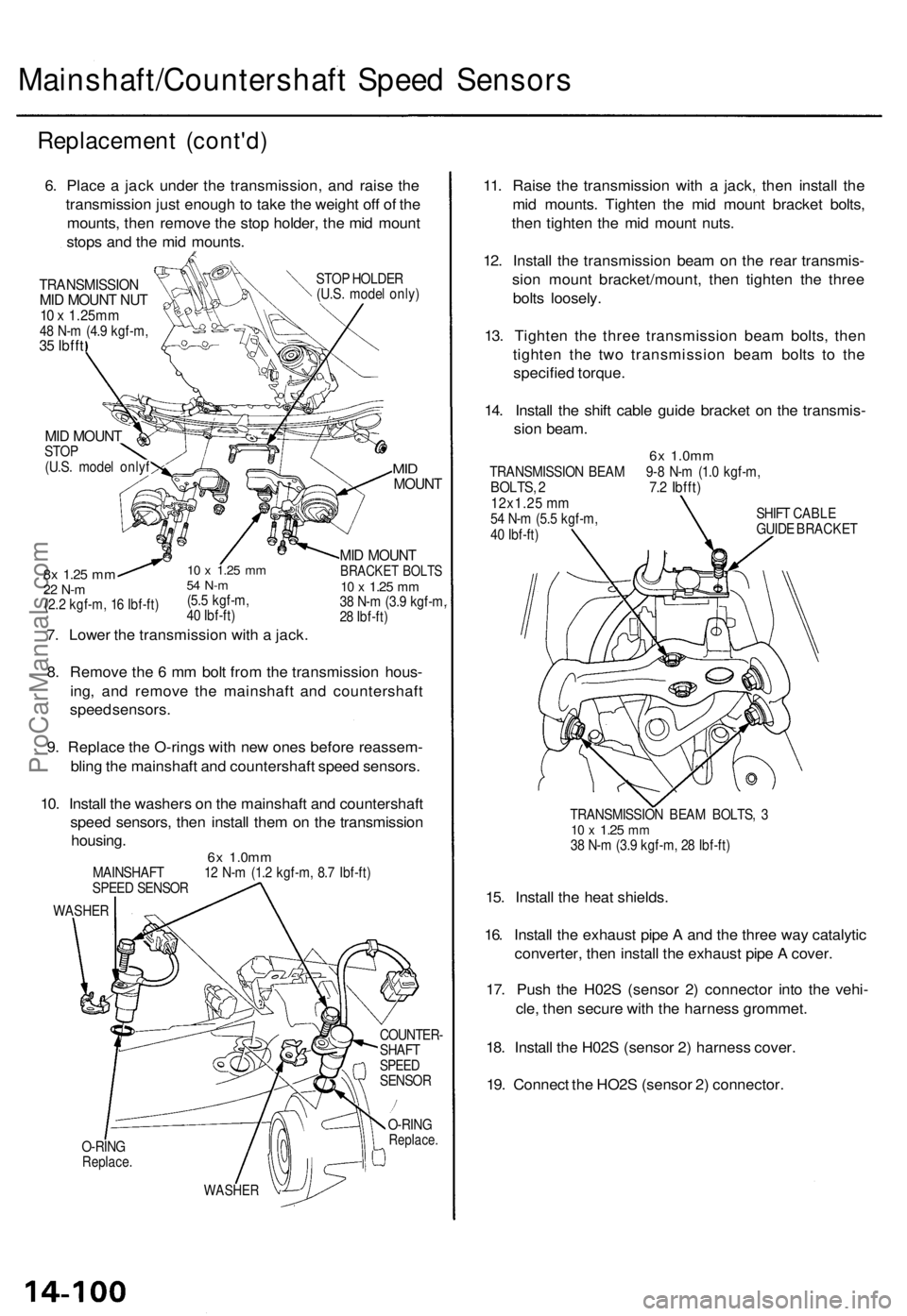
6. Place a jack under the transmission, and raise the
transmission just enough to take the weight off of the
mounts, then remove the stop holder, the mid mount
stops and the mid mounts.
TRANSMISSION
MID MOUNT NUT
10 x 1.25mm
48 N-m (4.9 kgf-m,
35 Ibfft
STOP HOLDER
(U.S. model only)
MID MOUNT
STOP
(U.S. model onlyf
10 x
1.25
mm
54 N-m
(5.5 kgf-m,
40 Ibf-ft)
7. Lower the transmission with a jack.
8x
1.25
mm
22 N-m
(2.2 kgf-m, 16 Ibf-ft)
MID
MOUNT
MID MOUNT
BRACKET BOLTS
10 x
1.25
mm
38 N-m (3.9 kgf-m,
28 Ibf-ft)
8. Remove the 6 mm bolt from the transmission hous-
ing, and remove the mainshaft and countershaft
speed sensors.
9. Replace the O-rings with new ones before reassem-
bling the mainshaft and countershaft speed sensors.
10. Install the washers on the mainshaft and countershaft
speed sensors, then install them on the transmission
housing.
6x
1.0mm
MAINSHAFT 12 N-m (1.2 kgf-m, 8.7 Ibf-ft)
SPEED SENSOR
WASHER
O-RING
Replace.
COUNTER-
SHAFT
SPEED
SENSOR
O-RING
Replace.
WASHER
11. Raise the transmission with a jack, then install the
mid mounts. Tighten the mid mount bracket bolts,
then tighten the mid mount nuts.
12. Install the transmission beam on the rear transmis-
sion mount bracket/mount, then tighten the three
bolts loosely.
13. Tighten the three transmission beam bolts, then
tighten the two transmission beam bolts to the
specified torque.
14. Install the shift cable guide bracket on the transmis-
sion beam.
6x
1.0mm
TRANSMISSION BEAM 9-8 N-m (1.0 kgf-m,
BOLTS, 2 7.2 Ibfft)
12x1.25 mm
54 N-m (5.5 kgf-m,
40 Ibf-ft)
SHIFT CABLE
GUIDE BRACKET
TRANSMISSION BEAM BOLTS, 3
10 x
1.25
mm
38 N-m (3.9 kgf-m, 28 Ibf-ft)
15. Install the heat shields.
16. Install the exhaust pipe A and the three way catalytic
converter, then install the exhaust pipe A cover.
17. Push the H02S (sensor 2) connector into the vehi-
cle, then secure with the harness grommet.
18. Install the H02S (sensor 2) harness cover.
19. Connect the HO2S (sensor 2) connector.ProCarManuals.com
Page 343 of 1771
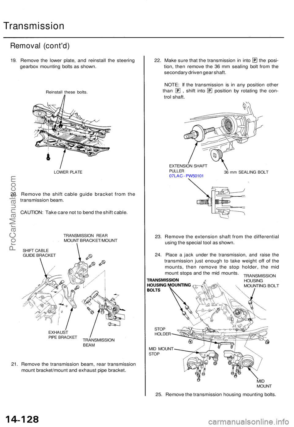
Transmission
Removal (cont'd )
19. Remov e th e lowe r plate , an d reinstal l th e steerin g
gearbo x mountin g bolt s a s shown .
Reinstal l thes e bolts .
LOWE R PLAT E
20. Remov e th e shif t cabl e guid e bracke t fro m th e
transmissio n beam .
CAUTION : Tak e car e no t t o ben d th e shif t cable .
TRANSMISSIO N REA RMOUN T BRACKET/MOUN T
SHIFT CABL EGUIDE BRACKE T
EXHAUSTPIPE BRACKE TTRANSMISSIO NBEAM
21. Remov e th e transmissio n beam , rea r transmissio n
moun t bracket/moun t an d exhaus t pip e bracket .
22. Mak e sur e tha t th e transmissio n in int o th e posi -
tion , the n remov e th e 3 6 m m sealin g bol t fro m th e
secondar y drive n gea r shaft .
NOTE : I f th e transmissio n i s i n an y positio n othe r
than , shift int o positio n b y rotatin g th e con -
tro l shaft .
EXTENSIO N SHAF TPULLE R07LAC - PW5010 136 m m SEALIN G BOL T
STOPHOLDE R
MID MOUN TSTOP
MIDMOUN T
25. Remov e th e transmissio n housin g mountin g bolts .
23
. Remov e th e extensio n shaf t fro m th e differentia l
usin g th e specia l too l a s shown .
24. Plac e a jac k unde r th e transmission , an d rais e th e
transmissio n jus t enoug h t o tak e weigh t of f o f th e
mounts , the n remov e th e sto p holder , th e mi d
moun t stop s an d th e mi d mounts .
TRANSMISSIO N
HOUSIN G
MOUNTIN G BOL T
ProCarManuals.com
Page 487 of 1771
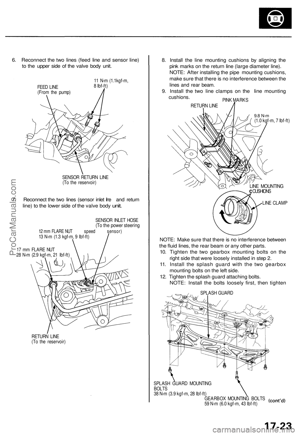
6. Reconnec t th e tw o line s (fee d lin e an d senso r line )
t o th e uppe r sid e o f th e valv e bod y unit .
FEED LIN E
(Fro m th e pump ) 1
1 N- m (1.1kgf-m ,
8 Ibf-ft )
SENSO R RETUR N LIN E
(T o th e reservoir )
7. Reconnec t th e tw o line s (senso r inle t lin e an d retur n
line )
to th e lowe r sid e of th e valv e bod y unit.
SENSO R INLE T HOS E(To th e powe r steerin g
12 m m FLAR E NU T speed sensor )13 N- m (1. 3 kgf-m , 9 Ibf-ft )
1 7 m m FLAR E NU T
2 8 N- m (2. 9 kgf-m , 2 1 Ibf-ft )
RETUR N LIN E
(T o th e reservoir )
8. Instal l th e lin e mountin g cushion s b y alignin g th e
pin k mark s o n th e retur n lin e (larg e diamete r line) .
NOTE : Afte r installin g th e pip e mountin g cushions ,
mak e sur e tha t ther e is n o interferenc e betwee n th e
line s an d rea r beam .
9. Instal l th e tw o lin e clamp s o n th e lin e mountin g
cushions.PINK MARK S
RETUR N LIN E
9.8 N- m(1.0 kgf-m , 7 Ibf-ft )
LINE MOUNTIN GCUSHIONS
LIN E CLAM P
NOTE: Mak e sur e tha t ther e is n o interferenc e betwee n
th e flui d lines , th e rea r bea m or an y othe r parts .
10 . Tighte n th e tw o gearbo x mountin g bolt s o n th e
righ t sid e tha t wer e loosel y installe d in ste p 2 .
11 . Instal l th e splas h guar d wit h th e tw o gearbo x
mountin g bolt s o n th e lef t side .
12 . Tighte n th e splas h guar d attachin g bolts .
NOTE : Instal l th e bolt s loosel y first , the n tighte n
SPLAS H GUAR D
GEARBO X MOUNTIN G BOLT S
5 9 N- m (6. 0 kgf-m , 4 3 Ibf-ft )
SPLAS
H GUAR D MOUNTIN G
BOLTS38 N- m (3. 9 kgf-m , 2 8 Ibf-ft )
ProCarManuals.com
Page 558 of 1771
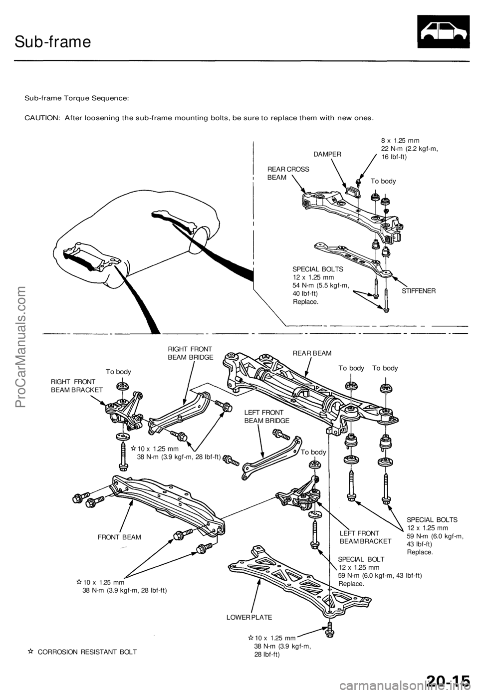
Sub-frame
Sub-frame Torque Sequence:
CAUTION: After loosening the sub-frame mounting bolts, be sure to replace them with new ones.
REAR CROSS
BEAM
DAMPER
8 x
1.25
mm
22 N-m (2.2 kgf-m,
16 Ibf-ft)
SPECIAL BOLTS
12 x
1.25
mm
54 N-m (5.5 kgf-m,
40 Ibf-ft)
Replace.
STIFFENER
RIGHT FRONT
BEAM BRIDGE
REAR BEAM
To body
To body To body
RIGHT FRONT
BEAM BRACKET
10 x
1.25
mm
38 N-m (3.9 kgf-m, 28 Ibf-ft)
SPECIAL BOLT
12 x
1.25
mm
59 N-m (6.0 kgf-m, 43 Ibf-ft)
Replace.
SPECIAL BOLTS
12 x
1.25
mm
59 N-m (6.0 kgf-m,
43 Ibf-ft)
Replace.
CORROSION RESISTANT BOLT
10 x
1.25
mm
38 N-m (3.9 kgf-m,
28 Ibf-ft)
To body
LEFT FRONT
BEAM BRIDGE
To body
10 x
1.25
mm
38 N-m (3.9 kgf-m, 28 Ibf-ft)
FRONT BEAM
LEFT FRONT
BEAM BRACKET
LOWER PLATEProCarManuals.com
Page 773 of 1771
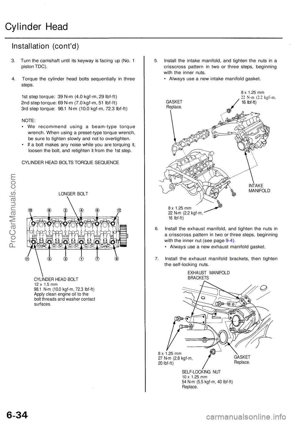
Cylinder Hea d
Installatio n (cont'd )
3. Tur n th e camshaf t unti l it s keywa y i s facin g u p (No . 1
pisto n TDC) .
4 . Torqu e th e cylinde r hea d bolt s sequentiall y i n thre e
steps .
1s t ste p torque : 3 9 N- m (4. 0 kgf-m , 2 9 Ibf-ft )
2n d ste p torque : 6 9 N- m (7. 0 kgf-m , 5 1 Ibf-ft )
3r d ste p torque : 98. 1 N- m (10. 0 kgf-m , 72. 3 Ibf-ft )
NOTE :
• W e recommen d usin g a beam-typ e torqu e
wrench . Whe n usin g a preset-typ e torqu e wrench ,
b e sur e t o tighte n slowl y an d no t t o overtighten .
• I f a bol t make s an y nois e whil e yo u ar e torquin g it ,
loose n th e bolt , an d retighte n it fro m th e 1s t step .
CYLINDE R HEA D BOLT S TORQU E SEQUENC E
LONGER BOL T
CYLINDE R HEA D BOL T
12 x 1. 5 m m98. 1 N- m (10. 0 kgf-m , 72. 3 Ibf-ft )Apply clea n engin e oi l t o th ebol t thread s an d washe r contac tsurfaces .
5.
6.
7 .
Instal l th e intak e manifold , an d tighte n th e nut s i n a
crisscros s patter n i n tw o o r thre e steps , beginnin g
wit h th e inne r nuts .
• Alway s us e a ne w intak e manifol d gasket .
GASKE TReplace .
8 x 1.2 5 mm22 N- m (2. 2 kgf-m ,16 Ibf-ft )
INTAK EMANIFOL D
8 x 1.2 5 mm22 N- m (2. 2 kgf-m ,16 Ibf-ft )
Install th e exhaus t manifold , an d tighte n th e nut s i n
a crisscros s patter n in tw o o r thre e steps , beginnin g
wit h th e inne r nu t (se e pag e 9-4 ).
• Alway s us e a ne w exhaus t manifol d gasket .
Instal l th e exhaus t manifol d brackets , the n tighte n
th e self-lockin g nuts .
EXHAUS T MANIFOL DBRACKETS
8 x 1.2 5 mm27 N- m (2. 8 kgf-m ,
2 0 Ibf-ft )GASKE TReplace .
SELF-LOCKIN G NU T10 x 1.2 5 mm54 N- m (5. 5 kgf-m , 4 0 Ibf-ft )
Replace .
ProCarManuals.com