Page 1212 of 1771

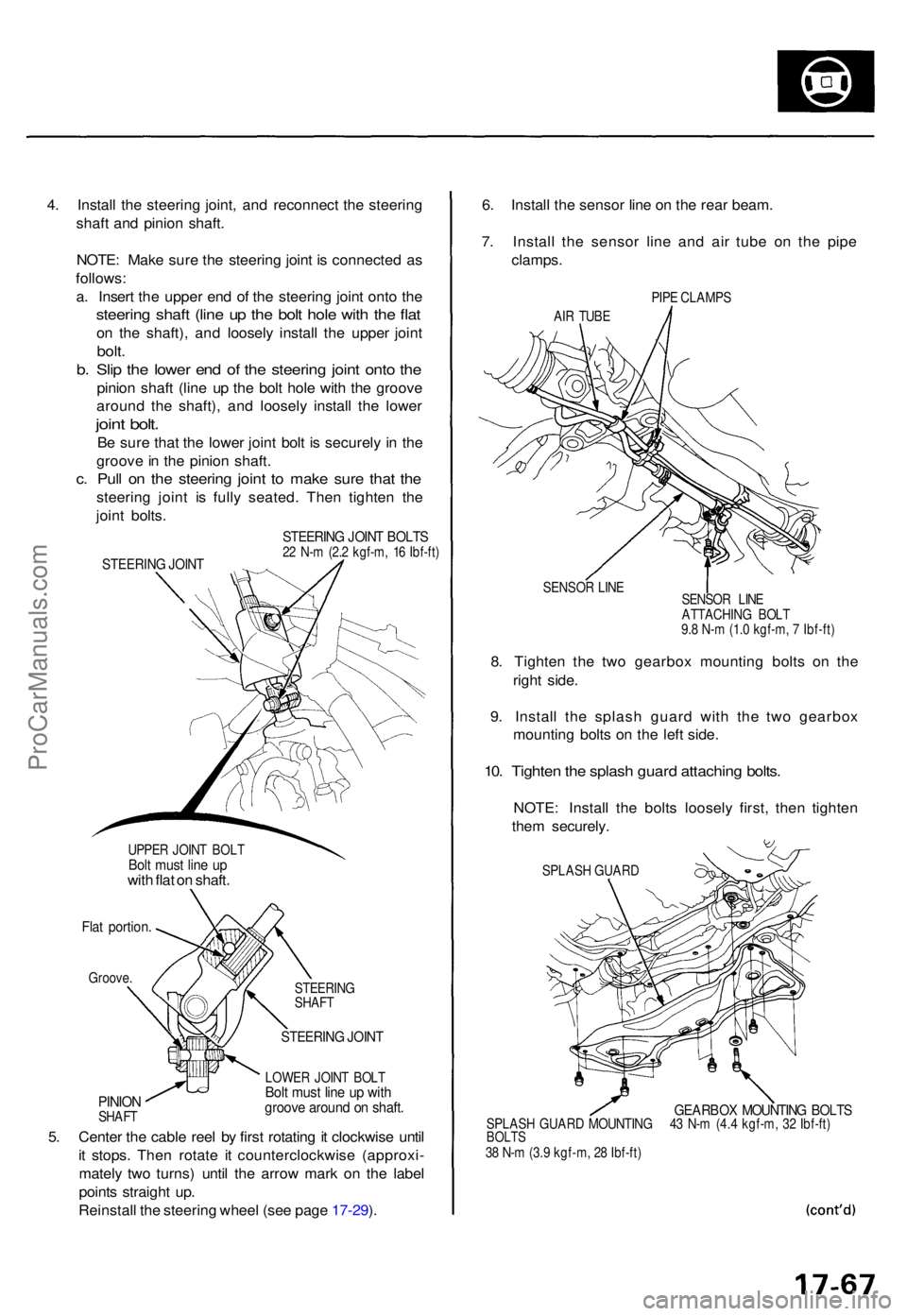
4. Instal l th e steerin g joint , an d reconnec t th e steerin g
shaf t an d pinio n shaft .
NOTE : Mak e sur e th e steerin g join t i s connecte d a s
follows :
a . Inser t th e uppe r en d o f th e steerin g join t ont o th e
steerin g shaf t (lin e u p th e bol t hol e wit h th e fla t
on th e shaft) , an d loosel y instal l th e uppe r join t
bolt.
b. Sli p th e lowe r en d o f th e steerin g join t ont o th e
pinio n shaf t (lin e u p th e bol t hol e wit h th e groov e
aroun d th e shaft) , an d loosel y instal l th e lowe r
joint bolt .
Be sur e tha t th e lowe r join t bol t i s securel y i n th e
groov e in th e pinio n shaft .
c. Pul l o n th e steerin g join t t o mak e sur e tha t th e
steerin g join t i s full y seated . The n tighte n th e
join t bolts .
UPPE R JOIN T BOL TBolt mus t lin e u pwit h fla t o n shaft .
Flat portion .
Groove.
PINIONSHAF T STEERIN
G
SHAF T
STEERIN G JOIN T
LOWE R JOIN T BOL TBolt mus t lin e u p wit hgroov e aroun d o n shaft .
5. Cente r th e cabl e ree l b y firs t rotatin g it clockwis e unti l
i t stops . The n rotat e i t counterclockwis e (approxi -
matel y tw o turns ) unti l th e arro w mar k o n th e labe l
point s straigh t up .
Reinstal l th e steerin g whee l (se e pag e 17-29 ). 6
. Instal l th e senso r lin e o n th e rea r beam .
7 . Instal l th e senso r lin e an d ai r tub e o n th e pip e
clamps .
PIPE CLAMP S
AI R TUB E
SENSO R LIN E
8. Tighte n th e tw o gearbo x mountin g bolt s o n th e
righ t side .
9 . Instal l th e splas h guar d wit h th e tw o gearbo x
mountin g bolt s o n th e lef t side .
10. Tighte n th e splas h guar d attachin g bolts .
NOTE : Instal l th e bolt s loosel y first , the n tighte n
the m securely .
SPLASH GUAR D
GEARBO X MOUNTIN G BOLT SSPLAS H GUAR D MOUNTIN G 4 3 N- m (4. 4 kgf-m , 3 2 Ibf-ft )BOLT S38 N- m (3. 9 kgf-m , 2 8 Ibf-ft )
STEERIN G JOIN T BOLT S22 N- m (2. 2 kgf-m , 1 6 Ibf-ft )STEERIN G JOIN T
SENSO R LIN E
ATTACHIN G BOL T
9. 8 N- m (1. 0 kgf-m , 7 Ibf-ft )
ProCarManuals.com
Page 1213 of 1771

Steering Gearbo x
Installatio n (cont'd )
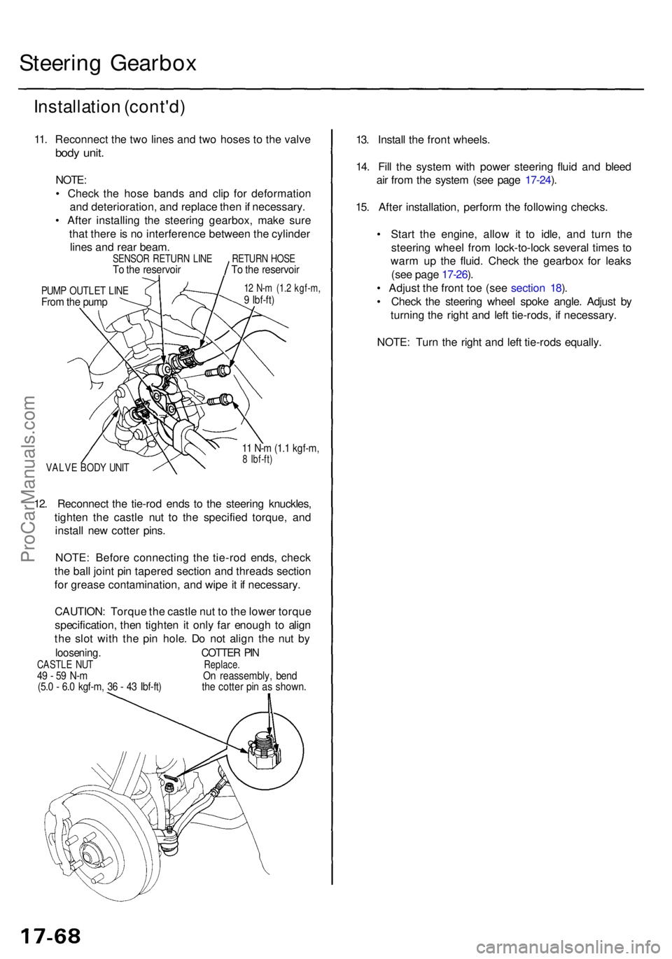
11. Reconnec t th e tw o line s an d tw o hose s t o th e valv e
body unit .
NOTE :
• Chec k th e hos e band s an d cli p fo r deformatio n
an d deterioration , an d replac e the n if necessary .
• Afte r installin g th e steerin g gearbox , mak e sur e
tha t ther e is n o interferenc e betwee n th e cylinde r
line s an d rea r beam .
PUMP OUTLE T LIN EFrom th e pum p
12 N- m (1. 2 kgf-m ,9 Ibf-ft )
VALV E BOD Y UNI T
11 N- m (1. 1 kgf-m ,8 Ibf-ft )
12. Reconnec t th e tie-ro d end s t o th e steerin g knuckles ,
tighte n th e castl e nu t t o th e specifie d torque , an d
instal l ne w cotte r pins .
NOTE : Befor e connectin g th e tie-ro d ends , chec k
th e bal l join t pi n tapere d sectio n an d thread s sectio n
fo r greas e contamination , an d wip e it i f necessary .
CAUTION : Torqu e th e castl e nu t t o th e lowe r torqu e
specification , the n tighte n it onl y fa r enoug h t o alig n
th e slo t wit h th e pi n hole . D o no t alig n th e nu t b y
loosening . COTTER PI NCASTL E NU T Replace.49 - 5 9 N- m O n reassembly , ben d(5.0 - 6. 0 kgf-m , 3 6 - 4 3 Ibf-ft ) th e cotte r pi n a s shown .
13. Instal l th e fron t wheels .
14 . Fil l th e syste m wit h powe r steerin g flui d an d blee d
ai r fro m th e syste m (se e pag e 17-24 ).
15 . Afte r installation , perfor m th e followin g checks .
• Star t th e engine , allo w i t t o idle , an d tur n th e
steerin g whee l fro m lock-to-loc k severa l time s t o
war m u p th e fluid . Chec k th e gearbo x fo r leak s
(se e pag e 17-26 ).
• Adjus t th e fron t to e (se e sectio n 18 ).
• Chec k th e steerin g whee l spok e angle . Adjus t b y
turnin g th e righ t an d lef t tie-rods , i f necessary .
NOTE : Tur n th e righ t an d lef t tie-rod s equally .
SENSO R RETUR N LIN ETo th e reservoi rRETURN HOS ETo th e reservoi r
ProCarManuals.com
Page 1450 of 1771
3. Pull the trunk side trim back, then remove the nut
from the trunk area on each side.
4. Remove the nuts from under the rear floor on each
side, then remove the absorber and rear bumper
beam. Remove the nuts, then remove the rear bumper
upper beam.
8 x
1.25
mm
22 N-m (2.2 kgf-m,
16 Ibf-ft)
6 x 1.0 mm
9.8 N-m (1.0 kgf-m,
7.2 Ibf-ft)
INNER
CLIP
NUT
REAR BUMPER
UPPER BEAM
REAR BUMPER
BEAM
5. Installation is the reverse of the removal procedure.
NOTE:
If necessary, replace any damaged clips.
When installing the trunk side trim, install the
clips as follows.
a. Pull the inner clip up as shown.
INNER
CLIP
b. Install the clip in the trunk side trim, then push the
inner clip until it's flush.
INNER CLIP
CLIP
Make sure the rear bumper engages the side
clips and hooks on each side securely.
SIDE
CLIPS
REAR BUMPER
UPPER BEAM
REAR
BUMPER
ABSORBER
HOOKS
TRUNK
SIDE
TRIMProCarManuals.com
Page 1476 of 1771
Sub-frame
Sub-frame Torque Sequence:
CAUTION: After loosening the sub-frame mounting bolts, be sure to replace them with new ones.
To body
REAR CROSS
BEAM
SPECIAL BOLTS
1 2x
1.25
mm
54 N-m (5.5 kgf-m,
40 Ibf-ft)
Replace.
To body
To body
SPECIAL BOLT
14 x 1.5 mm
95 N-m (9.7 kgf-m,
70 Ibf-ft)
Replace.
10 x
1.25
mm
38 N-m (3.9 kgf-m,
28 Ibf-ft)
LOWER PLATE
SPECIAL BOLT
14 x 1.5 mm
95 N-m (9.7 kgf-m,
70 Ibf-ft)
Replace.
SPECIAL BOLT
12 x
1.25
mm
64 N-m (6.5 kgf-m,
47 Ibf-ft)
Replace.
FRONT BEAMProCarManuals.com
Page 1542 of 1771
Relay and Control Unit Locations
Dashboard (cont'd)
ABS FAIL-SAFE RELAY
('97-98 models)
ABS FRONT FAIL-SAFE RELAY
('95 - 96 models)
FOG LIGHT RELAY
BLOWER MOTOR
HIGH RELAY
ABS REAR
FAIL-SAFE RELAY
('95 - 96 models)
UNDER-DASH
RELAY BOX
LOW BEAM
CUT RELAY
(Canada)
POWER MIRROR
DEFOGGER RELAY
(Canada)
ECM
DAYTIME
RUNNING LIGHTS
CONTROL UNIT
(Canada)
BLOWER
MOTOR
RELAY
HORN RELAYProCarManuals.com
Page 1548 of 1771
Headlight relay
Rear window defogger relay
Normally-closed Type:
1. Check for continuity between the terminals.
There should be no continuity between the No. 1
and No. 3 terminals when power and ground are
connected to the No. 2 and No. 4 terminals.
There should be continuity between the No. 1 and
No. 3 terminals when power is disconnected.
Low beam cut relay (Canada)
Five-terminal type:
1. Check for continuity between the terminals.
There should be continuity between the No. 1 and
No. 2 terminals when power and ground are con-
nected to the No. 3 and No. 5 terminals.
There should be continuity between the No. 2 and
No. 4 terminals when power is disconnected.
Dimmer relay
Intermittent wiper relay
Moonroof open relay
Moonroof close relayProCarManuals.com
Page 1595 of 1771
Bulb Locations
GAUGE LIGHTS
(1.4
W x 2)
HIGH BEAM INDICATOR LIGHT (1.4 W)
SEAT BELT REMINDER LIGHT (1.4 W)
RIGHT TURN SIGNAL INDICATOR LIGHT (1.4 W)
MALFUNCTION INDICATOR LAMP
(MIL) (1.4
W)
LOW FUEL
INDICATOR LIGHT (3 W)
BRAKE SYSTEM LIGHT (1.4 W)
LEFT TURN SIGNAL INDICATOR LIGHT (1.4 W)
SRS INDICATOR LIGHT (1.4 W)
(On the SRS printed circuit board)
CHARGING SYSTEM LIGHT (1.4 W)
LOW ENGINE OIL PRESSURE
INDICATOR LIGHT (1.4 W)
ABS INDICATOR LIGHT (1.4 W)
DRL INDICATOR
LIGHT (1.4 W) (Canada)
CRUISE LIGHT (2 W)
A/T GEAR POSITION INDICATOR LIGHTS (1.12 W x 7)
GAUGE LIGHTS
(3.4
W x 2)
SAFETY
INDICATOR
LIGHTS
(1.12
W x 6)
GAUGE LIGHTS
(3.4
W x 3)ProCarManuals.com