1995 ACURA TL light
[x] Cancel search: lightPage 85 of 1771
Valves, Valv e Spring s an d Valv e Seal s
Remova l
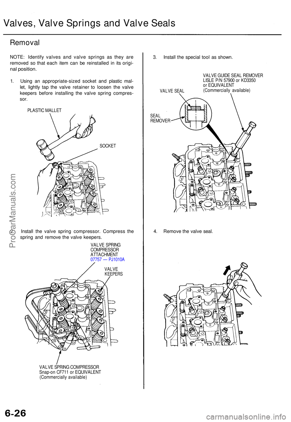
NOTE: Identif y valve s an d valv e spring s a s the y ar e
remove d s o tha t eac h ite m ca n b e reinstalle d i n it s origi -
nal position .
1. Usin g a n appropriate-size d socke t an d plasti c mal -
let , lightl y ta p th e valv e retaine r t o loose n th e valv e
keeper s befor e installin g th e valv e sprin g compres -
sor.
PLASTI C MALLE T
SOCKET
2. Instal l th e valv e sprin g compressor . Compres s th e
sprin g an d remov e th e valv e keepers .
VALVE SPRIN G
COMPRESSO R
ATTACHMEN T
0775 7 — PJ1010 A
VALVEKEEPER S
VALVE SPRIN G COMPRESSO R
Snap-o n CF71 1 o r EQUIVALEN T
(Commerciall y available )
3. Instal l th e specia l too l a s shown .
VALVE SEA L
VALV E GUID E SEA L REMOVE R
LISL E P/ N 5790 0 o r KD335 0
o r EQUIVALEN T
(Commerciall y available )
SEALREMOVE R
4. Remov e th e valv e seal .
ProCarManuals.com
Page 94 of 1771
Hydraulic Tappets
Valve Installation
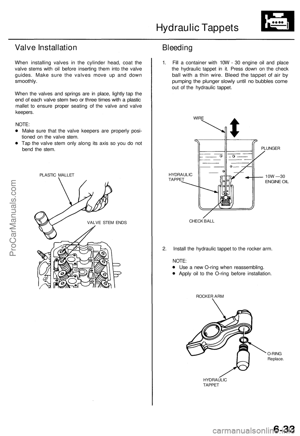
When installing valves in the cylinder head, coat the
valve stems with oil before inserting them into the valve
guides. Make sure the valves move up and down
smoothly.
When the valves and springs are in place, lightly tap the
end of each valve stem two or three times with a plastic
mallet to ensure proper seating of the valve and valve
keepers.
NOTE:
Make sure that the valve keepers are properly posi-
tioned on the valve stem.
Tap the valve stem only along its axis so you do not
bend the stem.
PLASTIC MALLET
Bleeding
VALVE STEM ENDS
1. Fill a container with 10W - 30 engine oil and place
the hydraulic tappet in it. Press down on the check
ball with a thin wire. Bleed the tappet of air by
pumping the plunger slowly until no bubbles come
out of the hydraulic tappet.
WIRE
PLUNGER
10W —30
ENGINE OIL
HYDRAULIC
TAPPET
CHECK BALL
2. Install the hydraulic tappet to the rocker arm.
NOTE:
Use a new O-ring when reassembling.
Apply oil to the O-ring before installation.
ROCKER ARM
O-RING
Replace.
HYDRAULIC
TAPPETProCarManuals.com
Page 95 of 1771
Camshafts/Rocker Arms and Camshaft Seals
Installation
CAUTION:
Make sure that all rockers are in alignment with their
valves when torquing the rocker assembly bolts.
To prevent the rocker arm assembly from coming
apart, leave the camshaft holder bolts in the holes.
Handle the rocker arms carefully so that the oil does
not come out of the hydraulic tappets.
1.
2.
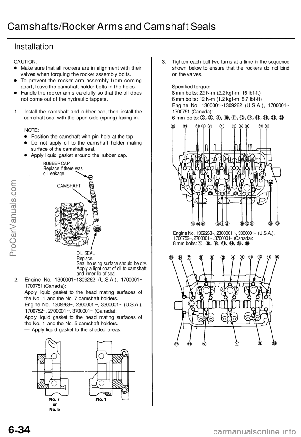
Install the camshaft and rubber cap, then install the
camshaft seal with the open side (spring) facing in.
NOTE:
Position the camshaft with pin hole at the top.
Do not apply oil to the camshaft holder mating
surface of the camshaft seal.
Apply liquid gasket around the rubber cap.
RUBBER CAP
Replace if there was
oil leakage.
CAMSHAFT
OIL SEAL
Replace.
Seal housing surface should be dry.
Apply a light coat of oil to camshaft
and inner lip of seal.
Engine No. 1300001~1309262 (U.S.A.), 1700001~
1700751 (Canada):
Apply liquid gasket to the head mating surfaces of
the No. 1 and the No. 7 camshaft holders.
Engine No. 1309263~, 2300001 ~, 3300001~ (U.S.A.),
1700752~, 2700001 ~, 3700001~ (Canada):
Apply liquid gasket to the head mating surfaces of
the No. 1 and the No. 5 camshaft holders.
— Apply liquid gasket to the shaded areas.
3. Tighten each bolt two turns at a time in the sequence
shown below to ensure that the rockers do not bind
on the valves.
Specified torque:
8 mm bolts: 22 N-m (2.2 kgf-m, 16 Ibf-ft)
6 mm bolts: 12 N-m (1.2 kgf-m, 8.7 Ibf-ft)
Engine No. 1300001~1309262 (U.S.A.), 1700001~
1700751 (Canada):
6 mm bolts:
Engine No. 1309263~, 2300001 ~, 3300001~ (U.S.A.),
1700752~, 2700001 ~. 3700001~ (Canada):
8 mm bolts:ProCarManuals.com
Page 97 of 1771
Cylinder Heads
Installation (cont'd)
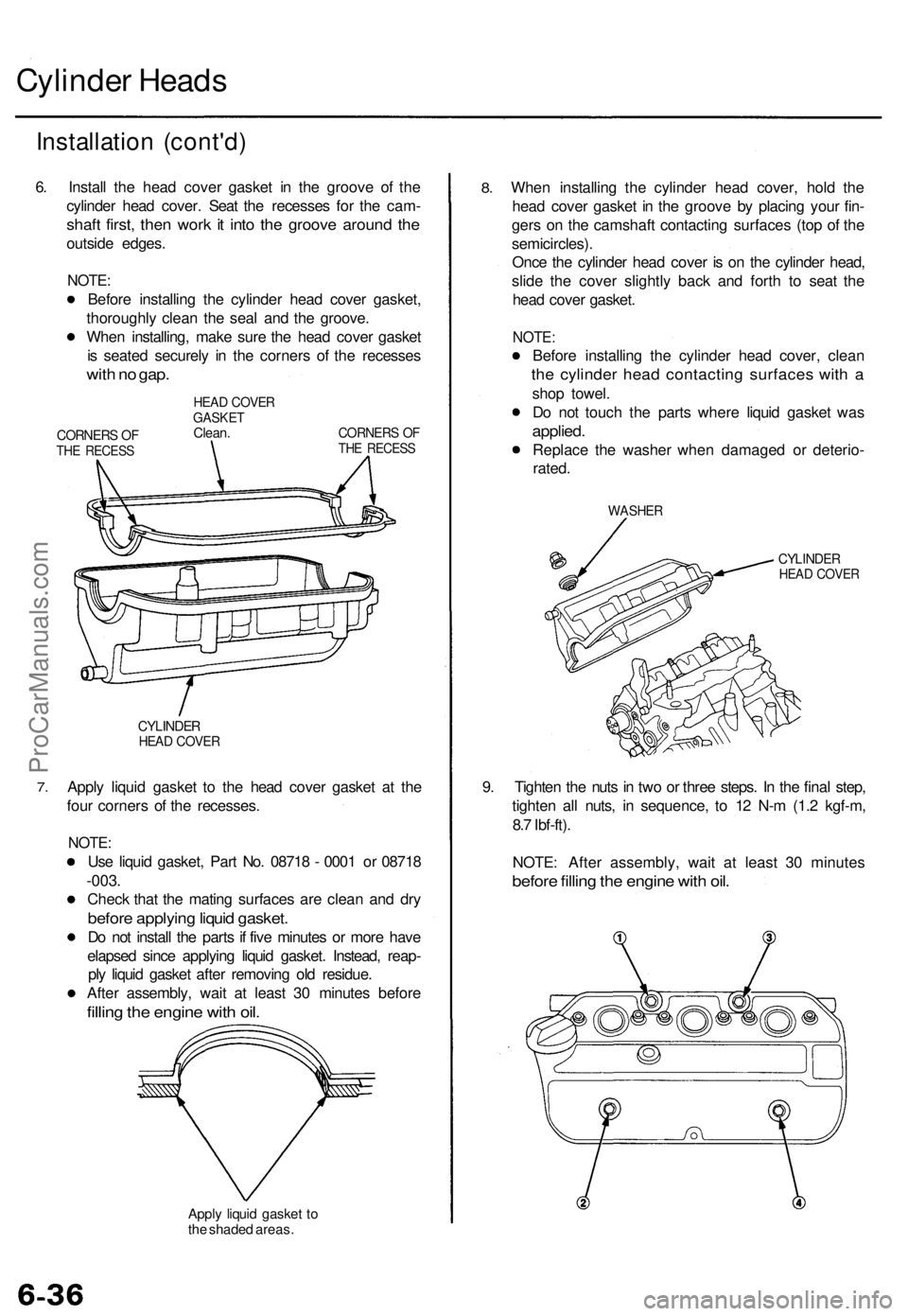
6. Install the head cover gasket in the groove of the
cylinder head cover. Seat the recesses for the cam-
shaft first, then work it into the groove around the
outside edges.
NOTE:
Before installing the cylinder head cover gasket,
thoroughly clean the seal and the groove.
When installing, make sure the head cover gasket
is seated securely in the corners of the recesses
with no gap.
CORNERS OF
THE RECESS
HEAD COVER
GASKET
Clean.
CORNERS OF
THE RECESS
7.
CYLINDER
HEAD COVER
Apply liquid gasket to the head cover gasket at the
four corners of the recesses.
NOTE:
Use liquid gasket, Part No. 08718 - 0001 or 08718
-003.
Check that the mating surfaces are clean and dry
before applying liquid gasket.
Do not install the parts if five minutes or more have
elapsed since applying liquid gasket. Instead, reap-
ply liquid gasket after removing old residue.
After assembly, wait at least 30 minutes before
filling the engine with oil.
Apply liquid gasket to
the shaded areas.
8.
When installing the cylinder head cover, hold the
head cover gasket in the groove by placing your fin-
gers on the camshaft contacting surfaces (top of the
semicircles).
Once the cylinder head cover is on the cylinder head,
slide the cover slightly back and forth to seat the
head cover gasket.
NOTE:
Before installing the cylinder head cover, clean
the cylinder head contacting surfaces with a
shop towel.
Do not touch the parts where liquid gasket was
applied.
Replace the washer when damaged or deterio-
rated.
WASHER
CYLINDER
HEAD COVER
9. Tighten the nuts in two or three steps. In the final step,
tighten all nuts, in sequence, to 12 N-m (1.2 kgf-m,
8.7 Ibf-ft).
NOTE: After assembly, wait at least 30 minutes
before filling the engine with oil.ProCarManuals.com
Page 121 of 1771
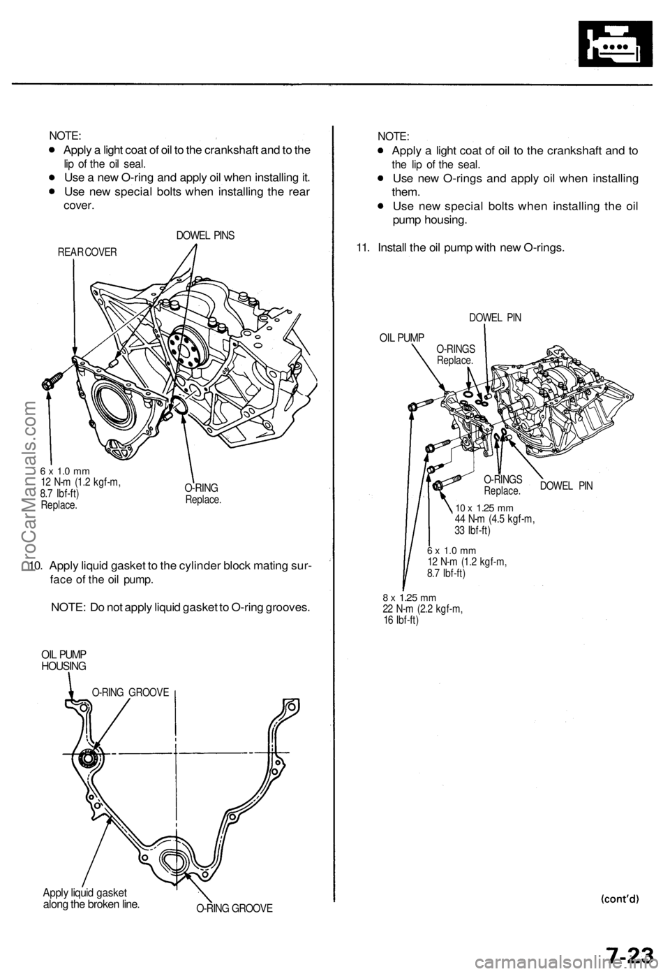
NOTE:
Apply a light coat of oil to the crankshaft and to the
lip of the oil seal.
Use a new O-ring and apply oil when installing it.
Use new special bolts when installing the rear
cover.
DOWEL PINS
REAR COVER
6 x 1.0 mm
12 N-m (1.2 kgf-m,
8.7 Ibf-ft)
Replace.
O-RING
Replace.
10. Apply liquid gasket to the cylinder block mating sur-
face of the oil pump.
NOTE: Do not apply liquid gasket to O-ring grooves.
OIL PUMP
HOUSING
Apply liquid gasket
along the broken line.
NOTE:
Apply a light coat of oil to the crankshaft and to
the lip of the seal.
Use new O-rings and apply oil when installing
them.
Use new special bolts when installing the oil
pump housing.
11. Install the oil pump with new O-rings.
DOWEL PIN
OIL PUMP
DOWEL PIN
10 x
1.25
mm
44 N-m (4.5 kgf-m,
33 Ibf-ft)
6 x 1.0 mm
12 N-m (1.2 kgf-m,
8.7 Ibf-ft)
8 x
1.25
mm
22 N-m (2.2 kgf-m,
16 Ibf-ft)
O-RING GROOVE
O-RINGS
Replace.
O-RINGS
Replace.
O-RING GROOVEProCarManuals.com
Page 138 of 1771
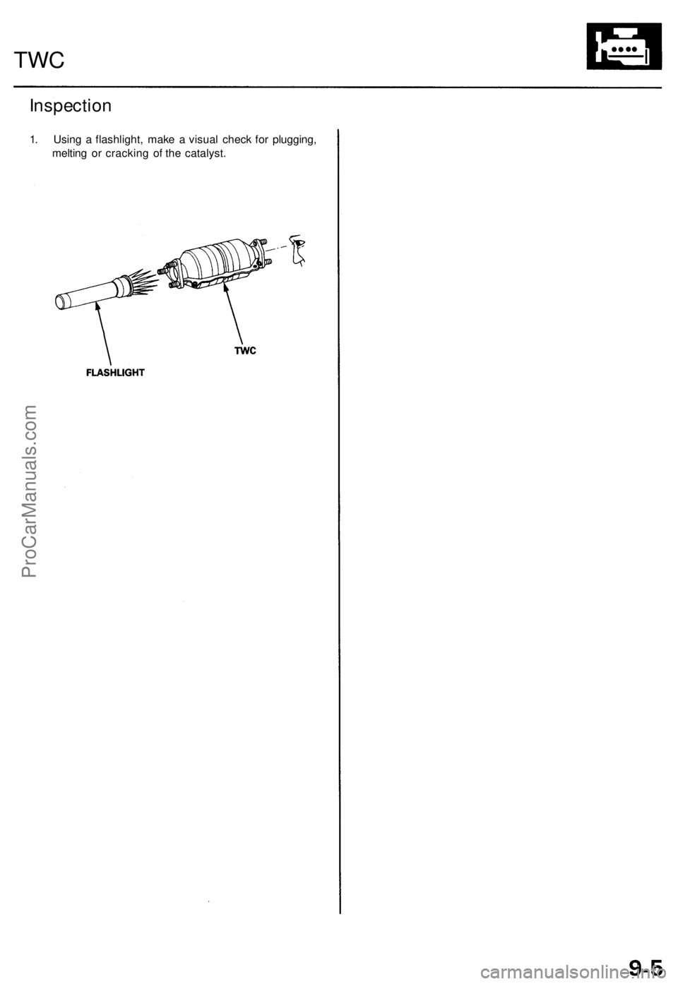
Inspection
1. Using a flashlight, make a visual check for plugging,
melting or cracking of the catalyst.
TWCProCarManuals.com
Page 183 of 1771
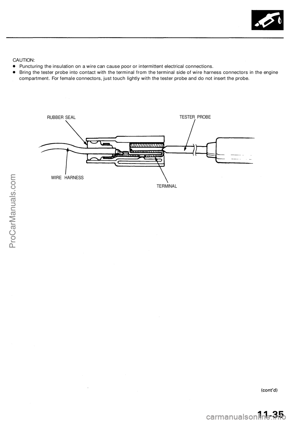
CAUTION:
Puncturing the insulation on a wire can cause poor or intermittent electrical connections.
Bring the tester probe into contact with the terminal from the terminal side of wire harness connectors in the engine
compartment. For female connectors, just touch lightly with the tester probe and do not insert the probe.
RUBBER SEAL
TESTER PROBE
WIRE HARNESS
TERMINALProCarManuals.com
Page 200 of 1771
PGM-FI System
System Description (cont'd)
3. Fuel Cut-off Control
During deceleration with the throttle valve closed, current to the fuel injectors is cut off to improve fuel economy at
speeds over 1,000 rpm.
Fuel cut-off action also takes place when engine speed exceeds 6,500 rpm, regardless of the position of the throttle
valve, to protect the engine from over-revving.
4. A/C Compressor Clutch Relay .
When the PCM receives a demand for cooling from the air conditioning system, it delays the compressor from being
energized, and enriches the mixture to assure a smooth transition to the A/C mode.
5. Evaporative Emission (EVAP) Purge Control Solenoid Valve
'96 model: When the engine coolant temperature is below 158°F (70°C), the PCM controls the EVAP purge control
solenoid valve which cuts vacuum to the EVAP purge control canister diaphragm.
'97 - 98 models: When the engine coolant temperature is above 99°F (37°C), the PCM controls the EVAP purge control
solenoid valve which controls vacuum to the EVAP purge control canister.
6. Intake Air Bypass (IAB) Low Control Solenoid Valve, Intake Air Bypass (IAB) High Control Solenoid Valve
When engine speed is below 3,350 rpm, the IAB High Control Solenoid Valve and IAB Low Control Solenoid Valve are
activated by a signal from the PCM. Intake air flows through a long chamber path, increasing torque at low RPM.
When engine speed is 3,350 - 3,950 rpm, the IAB Low Control Solenoid Valve is deactivated by the PCM. Intake air
flows through a short chamber path, increasing mid-range torque.
When the engine rpm is above 3,950 rpm, the IAB Low Control Solenoid Valve and IAB High Control Solenoid Valve are
deactivated by the PCM. This creates a very short intake path and increases high-speed torque.
7. Exhaust Gas Recirculation (EGR) Control Solenoid Valve
When the EGR is required for control of oxides of nitrogen (NOx) emissions, the PCM controls the EGR control solenoid
valve which supplies regulated vacuum to the EGR valve.
ECM Fail-safe/Back-up Functions
1. Fail-safe Function
When an abnormality occurs in a signal from a sensor, the PCM ignores that signal and assumes a pre-programmed
value for that sensor that allows the engine to continue to run.
2. Back-up Function
When an abnormality occurs in the PCM itself, the fuel injectors are controlled by a back-up circuit independent of the
system in order to permit minimal driving.
3. Self-diagnosis Function [Malfunction Indicator Lamp (MIL)]
When an abnormality occurs in a signal from a sensor, the PCM supplies ground for the MIL and stores the DTC in
erasable memory. When the ignition is initially turned on, the PCM supplies ground for the MIL for two seconds to
check the MIL bulb condition.
4. Two Driving Cycle Detection Method
To prevent false indications, the two driving cycle detection method is used for the H02S, fuel metering-related, idle
control system, ECT sensor, EGR system, TWC, EVAP control system and other self-diagnostic functions. When an
abnormality occurs, the PCM stores it in its memory. When the same abnormality recurs after the ignition switch is
turned OFF and ON (II) again, the PCM informs the driver by lighting the MIL.
However, to ease troubleshooting, this function is cancelled when you short the service check connector. The MIL will
then blink immediately when an abnormality occurs.ProCarManuals.com