1995 ACURA TL light
[x] Cancel search: lightPage 420 of 1771
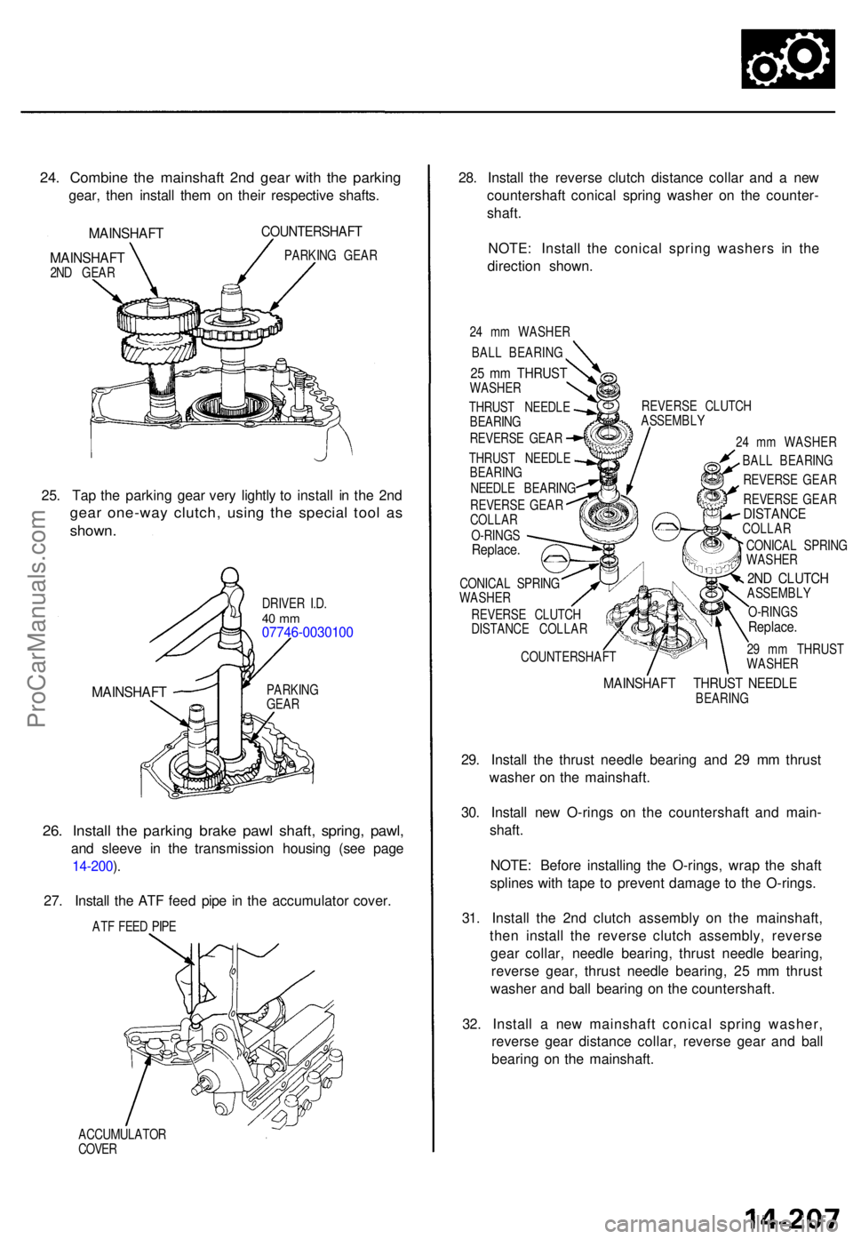
24. Combin e th e mainshaf t 2n d gea r wit h th e parkin g
gear, the n instal l the m o n thei r respectiv e shafts .
MAINSHAF T
MAINSHAF T
2ND GEA R
COUNTERSHAF T
PARKING GEA R
25. Ta p th e parkin g gea r ver y lightl y t o instal l i n th e 2n d
gea r one-wa y clutch , usin g th e specia l too l a s
shown .
DRIVE R I.D .40 m m07746-003010 0
MAINSHAFTPARKING
GEA R
26. Instal l th e parkin g brak e paw l shaft , spring , pawl ,
and sleev e i n th e transmissio n housin g (se e pag e
14-200 ).
27 . Instal l th e AT F fee d pip e i n th e accumulato r cover .
ATF FEE D PIP E
ACCUMULATO R
COVE R
28. Instal l th e revers e clutc h distanc e colla r an d a ne w
countershaf t conica l sprin g washe r o n th e counter -
shaft .
NOTE : Instal l th e conica l sprin g washer s i n th e
directio n shown .
24 m m WASHE R
BAL L BEARING
THRUS T NEEDL E
BEARIN G
REVERS E GEA R
THRUS T NEEDL E
BEARIN G
NEEDL E BEARIN G
REVERS E GEA R
COLLA R
O-RING S
Replace .
CONICA L SPRIN G
WASHE R
REVERS E CLUTC H
DISTANC E COLLA R
COUNTERSHAF TREVERS
E CLUTC H
ASSEMBL Y
24 m m WASHE R
BAL L BEARIN G
REVERS E GEA R
REVERS E GEA R
DISTANC ECOLLAR
CONICA L SPRIN G
WASHE R
2ND CLUTC HASSEMBL Y
O-RING S
Replace .
29 m m THRUS T
WASHE R
MAINSHAF T THRUS T NEEDL EBEARIN G
29. Instal l th e thrus t needl e bearin g an d 2 9 m m thrus t
washe r o n th e mainshaft .
30 . Instal l ne w O-ring s o n th e countershaf t an d main -
shaft .
NOTE : Befor e installin g th e O-rings , wra p th e shaf t
spline s wit h tap e t o preven t damag e t o th e O-rings .
31 . Instal l th e 2n d clutc h assembl y o n th e mainshaft ,
the n instal l th e revers e clutc h assembly , revers e
gea r collar , needl e bearing , thrus t needl e bearing ,
revers e gear , thrus t needl e bearing , 2 5 m m thrus t
washe r an d bal l bearin g o n th e countershaft .
32 . Instal l a ne w mainshaf t conica l sprin g washer ,
revers e gea r distanc e collar , revers e gea r an d bal l
bearin g o n th e mainshaft .
25 m m THRUS TWASHER
ProCarManuals.com
Page 439 of 1771
6. Us e a dial-typ e torqu e wrenc h o n th e driv e pinio n t o
measur e th e driv e pinio n bearin g preloa d (Tp) .
Standard : 1.4 2 - 1.9 1 N- m
(14. 5 - 19. 5 kgf-cm , 12. 6 - 16. 9 Ibf-in )
7. Reinstal l th e differentia l carrie r an d th e differentia l
cas e cover , the n measur e th e tota l bearin g preload .
Th e tota l bearin g preloa d shoul d excee d th e driv e
pinio n bearin g preloa d (Tp ) by :
Standard :
0.94 - 1.0 7 N- m (9. 6 - 10. 9 kgf-cm , 8.3 3 - 9.4 6 Ibf-in )
Example :
Total bearin g preloa d (fro m ste p 7 )
- T p (fro m ste p 6 )
= 0.9 4 - 1.0 7 N- m (9. 6 - 10. 9 kgf-cm , 8.3 3 - 9.4 6 Ibf-m )
Gear toot h contac t
8 . Remov e th e differentia l cas e cove r an d differentia l
carrier . Clea n an d pain t th e rin g gea r teet h lightl y an d
evenl y wit h Prussia n Blu e (o n bot h side s o f eac h
tooth) .
9 . Reinstal l th e differentia l carrie r an d th e differentia l
cas e cover , the n torqu e th e bolt s in a crisscros s pat -
ter n in severa l steps .
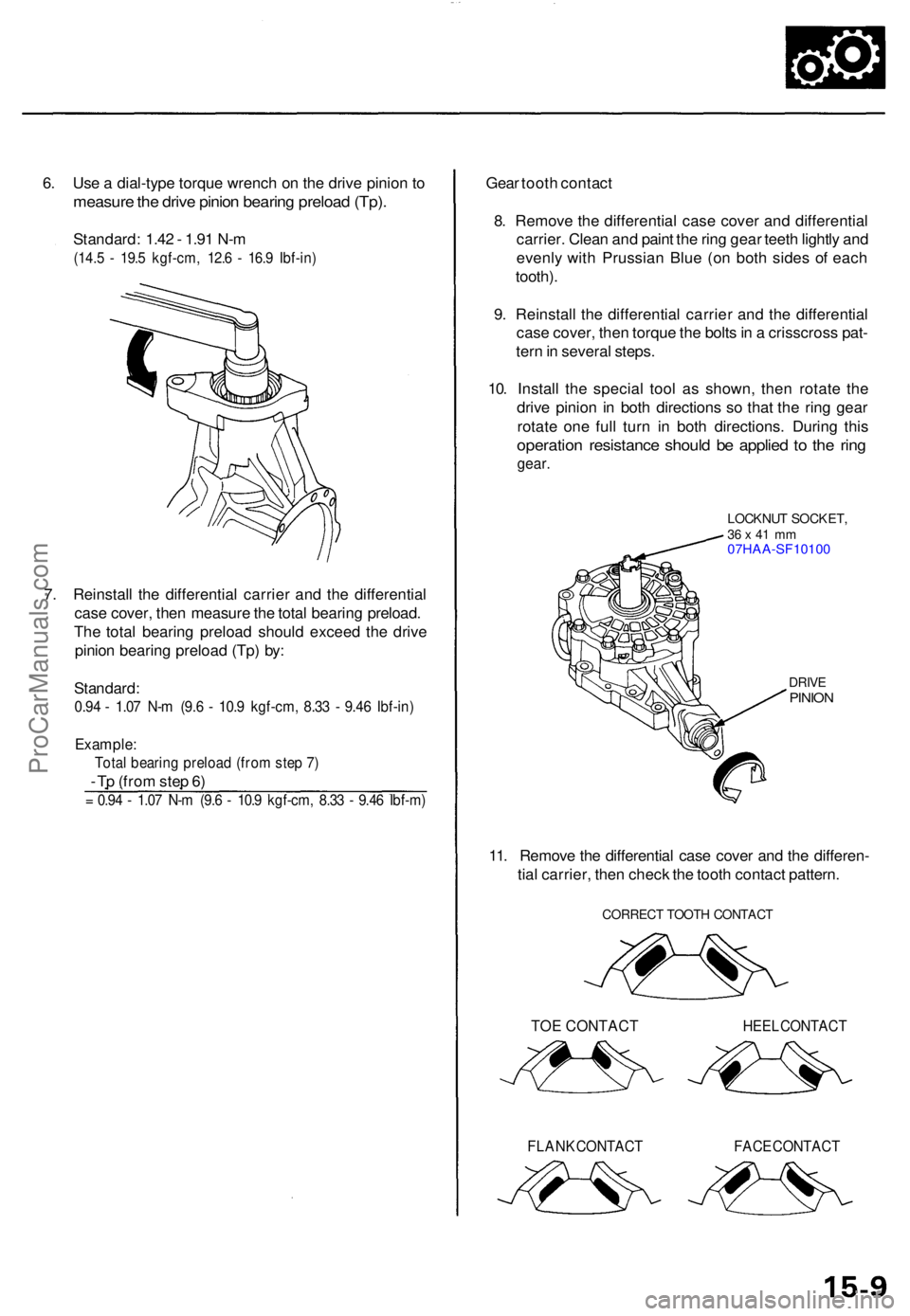
10 . Instal l th e specia l too l a s shown , the n rotat e th e
driv e pinio n i n bot h direction s s o tha t th e rin g gea r
rotat e on e ful l tur n i n bot h directions . Durin g thi s
operatio n resistanc e shoul d b e applie d t o th e rin g
gear .
LOCKNU T SOCKET ,36 x 41 m m07HAA-SF1010 0
DRIVEPINIO N
11. Remov e th e differentia l cas e cove r an d th e differen -
tia l carrier , the n chec k th e toot h contac t pattern .
CORREC T TOOT H CONTAC T
TOE CONTACT HEEL CONTAC T
FLANK CONTAC T FACE CONTAC T
ProCarManuals.com
Page 448 of 1771
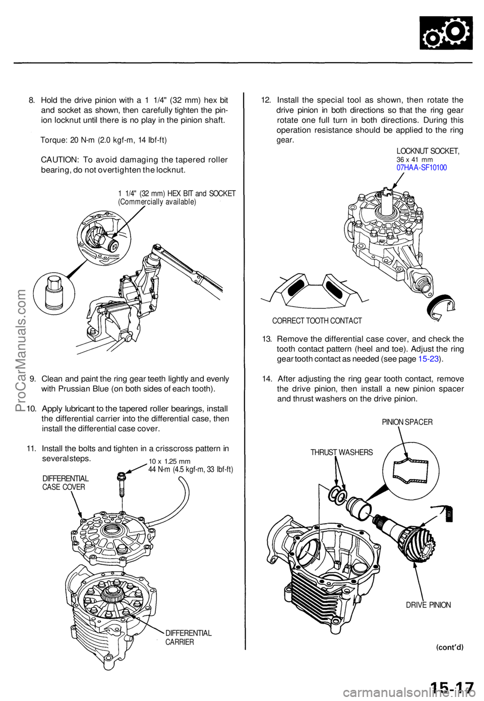
8. Hol d th e driv e pinio n wit h a 1 1/4 " (3 2 mm ) he x bi t
an d socke t a s shown , the n carefull y tighte n th e pin -
io n locknu t unti l ther e is n o pla y in th e pinio n shaft .
Torque : 2 0 N- m (2. 0 kgf-m , 1 4 Ibf-ft )
CAUTION : T o avoi d damagin g th e tapere d rolle r
bearing , d o no t overtighte n th e locknut .
1 1/4 " (3 2 mm ) HE X BI T an d SOCKE T(Commerciall y available )
9. Clea n an d pain t th e rin g gea r teet h lightl y an d evenl y
wit h Prussia n Blu e (o n bot h side s o f eac h tooth) .
10. Appl y lubrican t t o th e tapere d rolle r bearings , instal l
the differentia l carrie r int o th e differentia l case , the n
instal l th e differentia l cas e cover .
11 . Instal l th e bolt s an d tighte n in a crisscros s patter n in
severa l steps .
DIFFERENTIA LCASE COVE R
10 x 1.2 5 mm44 N- m (4. 5 kgf-m , 3 3 Ibf-ft )
DIFFERENTIA LCARRIER
12. Instal l th e specia l too l a s shown , the n rotat e th e
driv e pinio n i n bot h direction s s o tha t th e rin g gea r
rotat e on e ful l tur n i n bot h directions . Durin g thi s
operation resistanc e shoul d b e applie d t o th e rin g
gear .
LOCKNU T SOCKET ,36 x 41 m m07HA A-SF1010 0
CORREC T TOOT H CONTAC T
13. Remov e th e differentia l cas e cover , an d chec k th e
toot h contac t patter n (hee l an d toe) . Adjus t th e rin g
gea r toot h contac t a s neede d (se e pag e 15-23 ).
14 . Afte r adjustin g th e rin g gea r toot h contact , remov e
th e driv e pinion , the n instal l a ne w pinio n space r
an d thrus t washer s o n th e driv e pinion .
PINION SPACE R
THRUST WASHER S
DRIVE PINIO N
ProCarManuals.com
Page 450 of 1771
19. Clea n an d pain t th e rin g gea r teet h lightl y an d evenl y
wit h Prussia n Blu e (o n bot h side s o f eac h tooth) .
20 . Instal l th e differentia l carrie r int o th e differentia l
case , an d reinstal l th e differential case cover .
21 . Instal l th e bolt s an d tighte n i n a crisscros s patter n in
severa l steps .
Torque : 4 4 N- m (4. 5 kgf-m , 3 3 Ibf-ft )
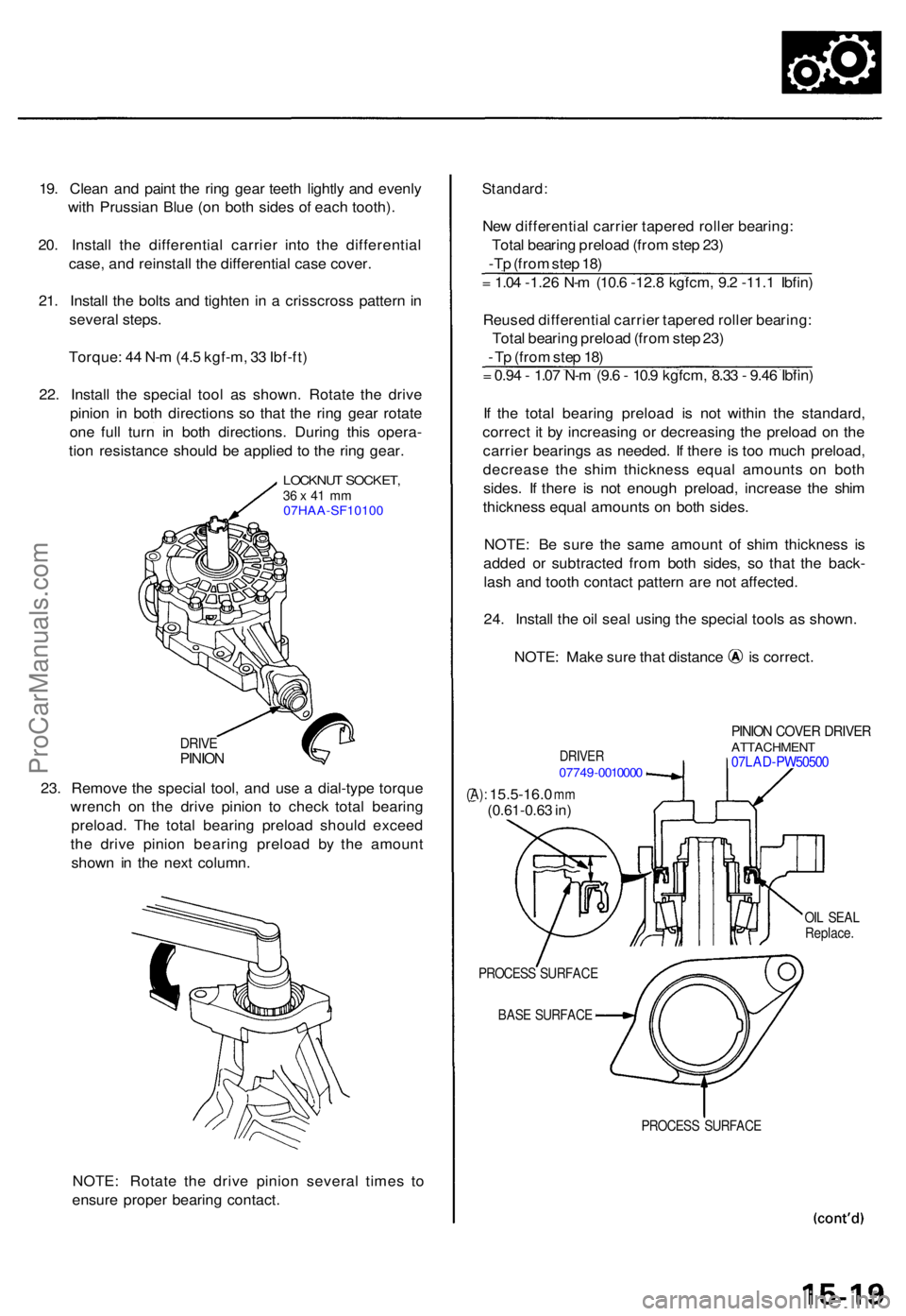
22 . Instal l th e specia l too l a s shown . Rotat e th e driv e
pinio n i n bot h direction s s o tha t th e rin g gea r rotat e
on e ful l tur n i n bot h directions . Durin g thi s opera -
tio n resistanc e shoul d b e applie d t o th e rin g gear .
LOCKNU T SOCKET ,36 x 41 m m07HAA-SF10100
DRIV EPINIO N
23. Remov e th e specia l tool , an d us e a dial-typ e torqu e
wrenc h o n th e driv e pinio n t o chec k tota l bearin g
preload . Th e tota l bearin g preloa d shoul d excee d
th e driv e pinio n bearin g preloa d b y th e amoun t
show n i n th e nex t column .
NOTE : Rotat e th e driv e pinio n severa l time s t o
ensur e prope r bearin g contact .
Standard :
New differentia l carrie r tapere d rolle r bearing :
Tota l bearin g preloa d (fro m ste p 23 )
-Tp (fro m ste p 18 )
= 1.0 4 -1.2 6 N- m (10. 6 -12. 8 kgfcm , 9. 2 -11. 1 Ibfin )
Reuse d differentia l carrie r tapere d rolle r bearing :
Tota l bearin g preloa d (fro m ste p 23 )
- T p (fro m ste p 18 )
= 0.9 4 - 1.0 7 N- m (9. 6 - 10. 9 kgfcm , 8.3 3 - 9.4 6 Ibfin )
I f th e tota l bearin g preloa d i s no t withi n th e standard ,
correc t i t b y increasin g o r decreasin g th e preloa d o n th e
carrie r bearing s a s needed . I f ther e i s to o muc h preload ,
decreas e th e shi m thicknes s equa l amount s o n bot h
sides . I f ther e i s no t enoug h preload , increase the shi m
thicknes s equa l amount s o n bot h sides .
NOTE : B e sur e th e sam e amoun t of shi m thicknes s i s
adde d o r subtracte d fro m bot h sides , s o tha t th e back -
las h an d toot h contac t patter n ar e no t affected .
24 . Instal l th e oi l sea l usin g th e specia l tool s a s shown .
NOTE: Mak e sur e tha t distanc e i s correct .
DRIVER07749-001000 0
PINION COVE R DRIVE RATTACHMEN T07LAD-PW5050 0
(A): 15.5-16. 0 mm(0.61-0.6 3 in )
OIL SEA L
Replace .
PROCES S SURFAC E
BAS E SURFAC E
PROCESS SURFAC E
ProCarManuals.com
Page 484 of 1771
Steering Gearbo x
Reassembl y (cont'd )
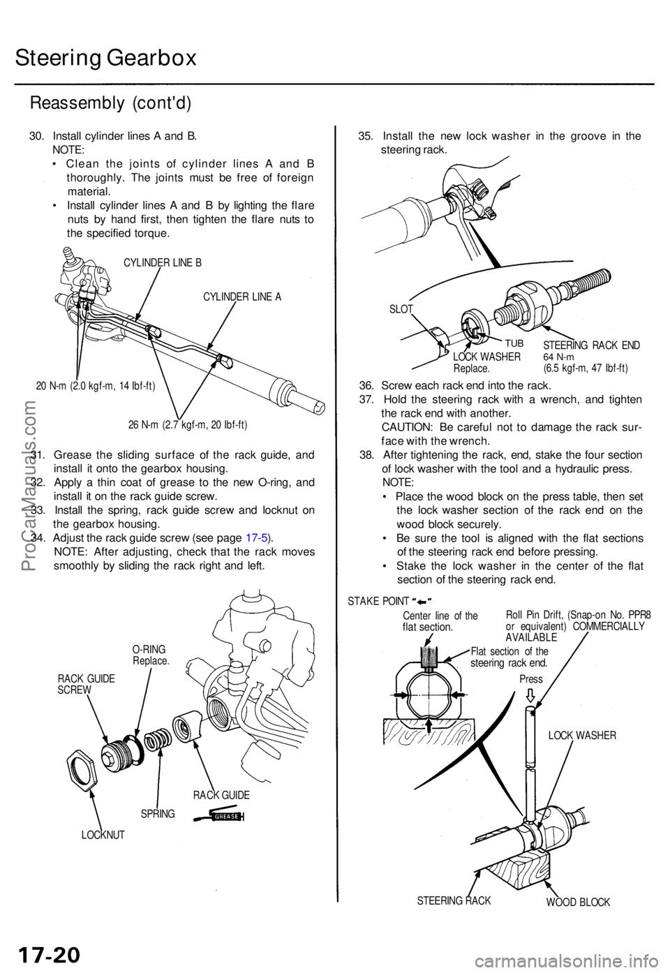
30. Instal l cylinde r line s A an d B .
NOTE :
• Clea n th e joint s o f cylinde r line s A an d B
thoroughly . Th e joint s mus t b e fre e o f foreig n
material .
• Instal l cylinde r line s A an d B by lightin g th e flar e
nut s b y han d first , the n tighte n th e flar e nut s t o
th e specifie d torque .
CYLINDE R LIN E B
CYLINDE R LIN E A
2 0 N- m (2. 0 kgf-m , 1 4 Ibf-ft )
2 6 N- m (2. 7 kgf-m , 2 0 Ibf-ft )
31. Greas e th e slidin g surfac e o f th e rac k guide , an d
instal l i t ont o th e gearbo x housing .
32 . Appl y a thi n coa t o f greas e t o th e ne w O-ring , an d
instal l i t o n th e rac k guid e screw .
33 . Instal l th e spring , rac k guid e scre w an d locknu t o n
th e gearbo x housing .
34 . Adjus t th e rac k guid e scre w (se e pag e 17-5 ).
NOTE : Afte r adjusting , chec k tha t th e rac k move s
smoothl y b y slidin g th e rac k righ t an d left .
RAC K GUID ESCRE W
LOCKNU T
35. Instal l th e ne w loc k washe r i n th e groov e i n th e
steerin g rack .
Cente r lin e o f th eflat section .Roll Pi n Drift , (Snap-o n No . PPR 8
o r equivalent ) COMMERCIALL Y
AVAILABLE
LOCK WASHE R
STEERIN G RAC K
WOOD BLOC K
SLO
T
TUB
36. Scre w eac h rac k en d int o th e rack .
37 . Hol d th e steerin g rac k wit h a wrench , an d tighte n
th e rac k en d wit h another .
CAUTION : B e carefu l no t t o damag e th e rac k sur -
fac e wit h th e wrench .
38 . Afte r tightenin g th e rack , end , stak e th e fou r sectio n
o f loc k washe r wit h th e too l an d a hydrauli c press .
NOTE:
• Plac e th e woo d bloc k o n th e pres s table , the n se t
th e loc k washe r sectio n o f th e rac k en d o n th e
woo d bloc k securely .
• B e sur e th e too l i s aligne d wit h th e fla t section s
o f th e steerin g rac k en d befor e pressing .
• Stak e th e loc k washe r i n th e cente r o f th e fla t
sectio n o f th e steerin g rac k end .
STEERIN G RAC K EN D64 N- m(6.5 kgf-m , 4 7 Ibf-ft )
LOC
K WASHE RReplace.
STAKE POIN T
Flat sectio n o f th e
steerin g rac k end .
Pres s
SPRIN GRAC
K GUID E
O-RIN
G
Replace .
ProCarManuals.com
Page 485 of 1771
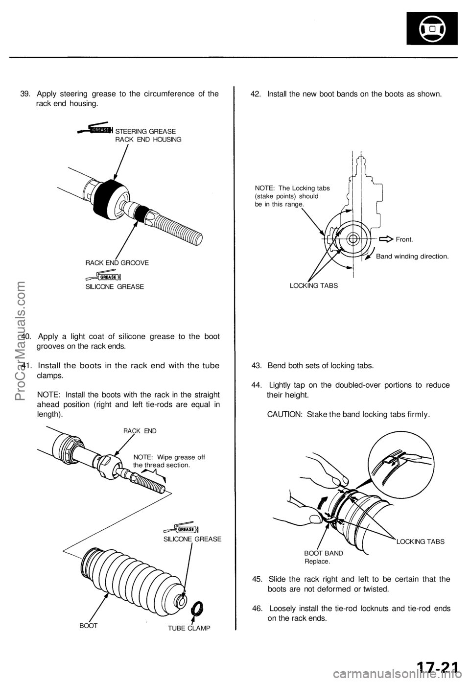
39. Appl y steerin g greas e t o th e circumferenc e o f th e
rac k en d housing .
STEERIN G GREAS E
RAC K EN D HOUSIN G
RAC K EN D GROOV E
40. Appl y a ligh t coa t o f silicon e greas e t o th e boo t
groove s o n th e rac k ends .
41. Instal l th e boot s i n th e rac k en d wit h th e tub e
clamps .
NOTE : Instal l th e boot s wit h th e rac k i n th e straigh t
ahea d positio n (righ t an d lef t tie-rod s ar e equa l i n
length) .
NOTE: Wip e greas e of fthe threa d section .
SILICON E GREAS E
BOO T
TUBE CLAM P
42. Instal l th e ne w boo t band s o n th e boot s a s shown .
NOTE: Th e Lockin g tab s
(stak e points ) shoul d
b e i n thi s range .
LOCKIN G TAB S
43. Ben d bot h set s o f lockin g tabs .
44 . Lightl y ta p o n th e doubled-ove r portion s t o reduc e
their height .
CAUTION : Stak e th e ban d lockin g tab s firmly .
LOCKIN G TAB S
BOO T BAN D
Replace .
45. Slid e th e rac k righ t an d lef t t o b e certai n tha t th e
boot s ar e no t deforme d o r twisted .
46 . Loosel y instal l th e tie-ro d locknut s an d tie-ro d end s
o n th e rac k ends .
SILICON E GREAS E
Band windin g direction .
Front.
RACK EN D
ProCarManuals.com
Page 496 of 1771
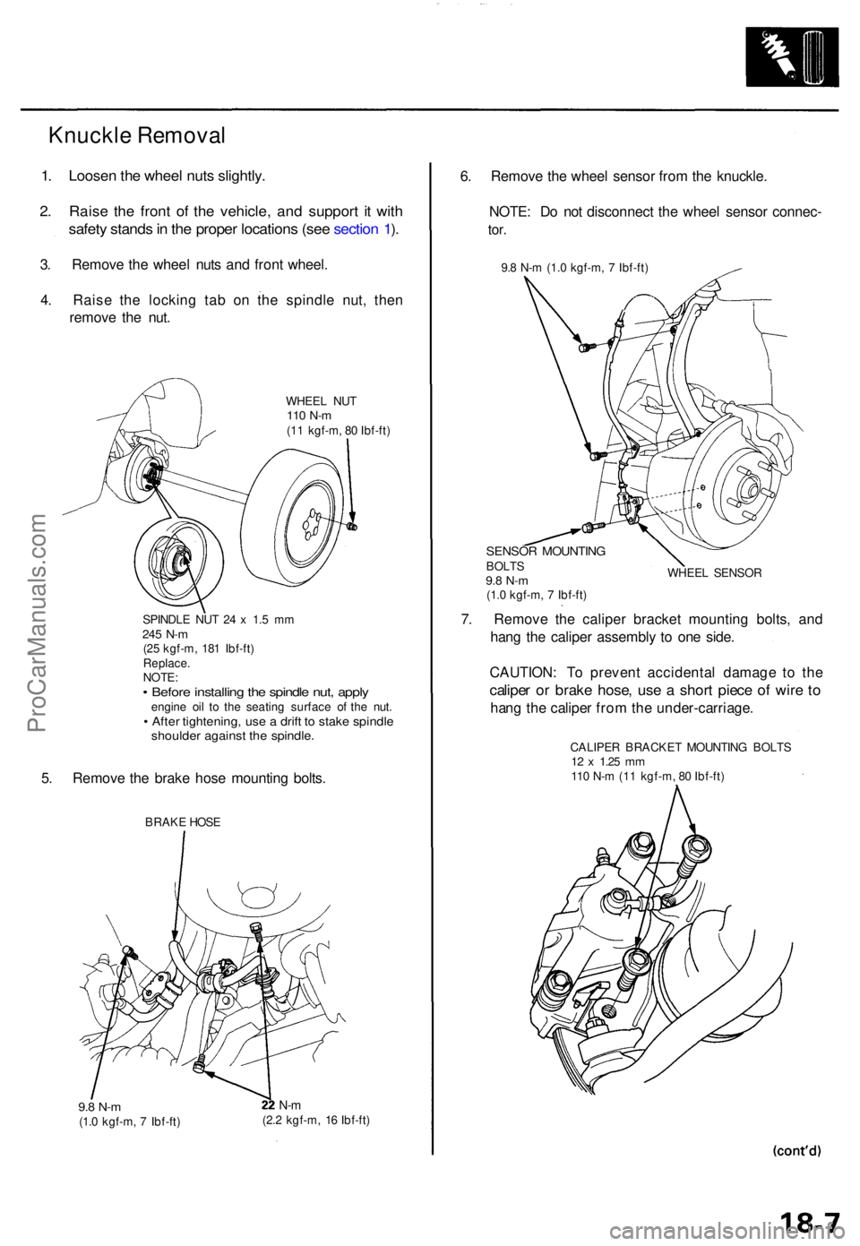
1. Loose n th e whee l nut s slightly .
2. Rais e th e fron t o f th e vehicle , an d suppor t i t wit h
safet y stand s in th e prope r location s (se e sectio n 1 ).
3 . Remov e th e whee l nut s an d fron t wheel .
4 . Rais e th e lockin g ta b o n th e spindl e nut , the n
remov e th e nut .
WHEE L NU T110 N- m(11 kgf-m , 8 0 Ibf-ft )
SPINDL E NU T 2 4 x 1. 5 m m
245 N- m(25 kgf-m , 18 1 Ibf-ft )
Replace .
NOTE :
• Befor e installin g th e spindl e nut , appl yengin e oi l t o th e seating surface o f th e nut .• Afte r tightening , us e a drif t t o stak e spindl eshoulde r agains t th e spindle .
5. Remov e th e brak e hos e mountin g bolts .
BRAK E HOS E
9.8 N- m(1.0 kgf-m , 7 Ibf-ft )
N-m(2. 2 kgf-m , 1 6 Ibf-ft )
6. Remov e th e whee l senso r fro m th e knuckle .
NOTE : D o no t disconnec t th e whee l senso r connec -
tor.
9.8 N- m (1. 0 kgf-m , 7 Ibf-ft )
SENSO R MOUNTIN GBOLTS9.8 N- m(1.0 kgf-m , 7 Ibf-ft ) WHEE
L SENSO R
7. Remov e th e calipe r bracke t mountin g bolts , an d
han g th e calipe r assembl y t o on e side .
CAUTION : T o preven t accidenta l damag e t o th e
calipe r o r brak e hose , us e a shor t piec e o f wir e t o
han g th e calipe r fro m th e under-carriage .
CALIPER BRACKE T MOUNTIN G BOLT S12 x 1.2 5 mm110 N- m (1 1 kgf-m , 8 0 Ibf-ft )
Knuckle Removal
ProCarManuals.com
Page 505 of 1771
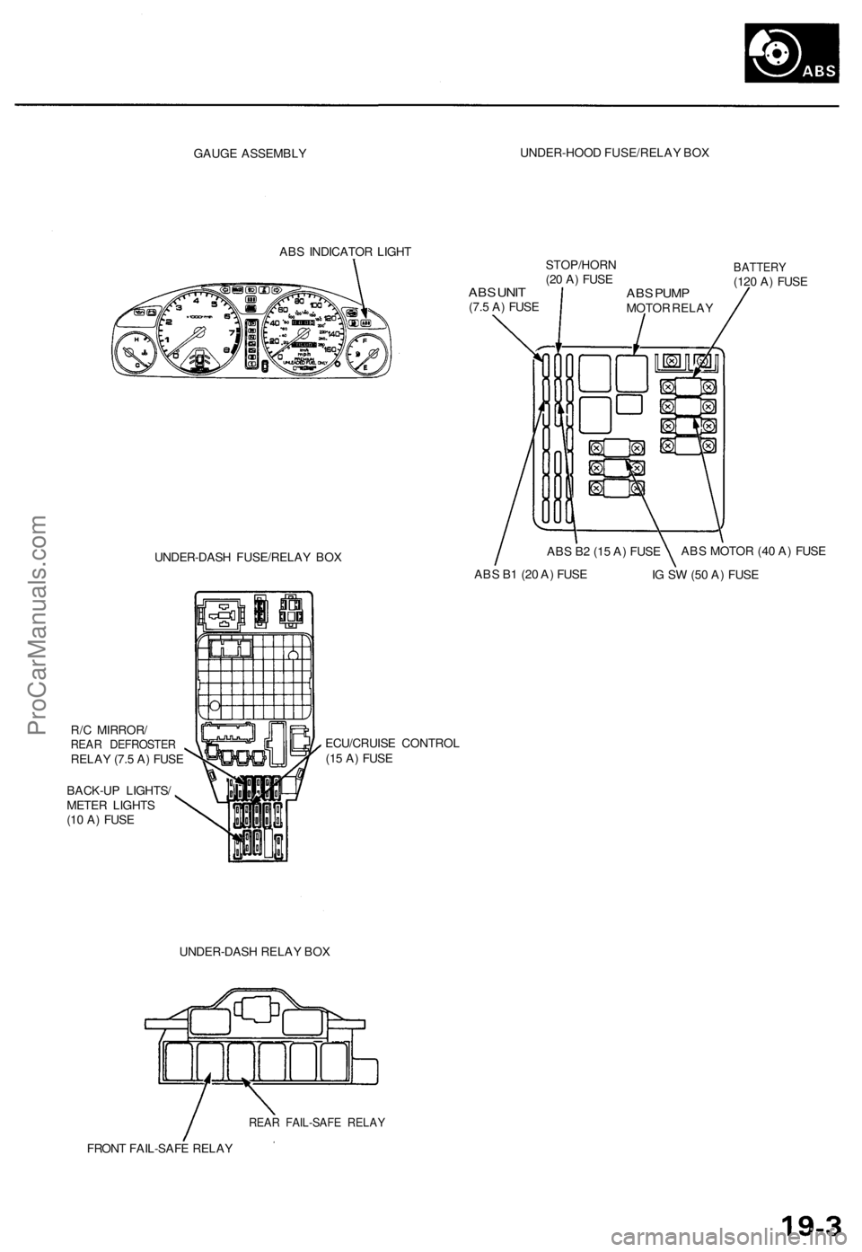
GAUGE ASSEMBL Y UNDER-HOO
D FUSE/RELA Y BO X
AB S INDICATO R LIGH T
ABS UNI T(7.5 A ) FUS ESTOP/HOR
N
(2 0 A ) FUS E
UNDER-DAS H FUSE/RELA Y BO X
BATTER Y(120 A ) FUS E
R/ C MIRROR /
REAR DEFROSTE RRELAY (7. 5 A ) FUS E
BACK-U P LIGHTS /
METE R LIGHT S
(1 0 A ) FUS E ECU/CRUIS
E CONTRO L
(1 5 A ) FUS E
UNDER-DAS H RELA Y BO X
REA R FAIL-SAF E RELA Y
FRONT FAIL-SAF E RELA Y
ABS PUM PMOTO R RELA Y
AB S B 1 (2 0 A ) FUS E
IG S W (5 0 A ) FUS E
AB
S B 2 (1 5 A ) FUS E AB
S MOTO R (4 0 A ) FUS E
ProCarManuals.com