Page 551 of 1771
Adjustment
NOTE: Before adjusting the hood, remove the support strut on each side from the hood, and loosen each hood mounting
bolt slightly.
1. Adjust the hood right and left, as well as fore and aft, by using the elongated holes on the hood hinge.
2. Turn the hood edge cushions, as necessary, to make the hood fit flush with the body at front and side edges.
3. Adjust the hood latch to obtain the proper height at the forward edge.
4. After adjustment, tighten each bolt securely.
HOOD
HINGE
6 x 1.0 mm
9.8 N-m (1.0 kgf-m,
7.2 Ibf-ft)
HOOD
HOOD EDGE
CUSHION
HOOD
LATCH
NOTE: Move the hood latch right or left until the striker
is centered in the hood latch as shown.
HOOD
LATCH
STRIKER
HOOD EDGE
CUSHION
(Hood side)
HOOD EDGE
CUSHION
(Body side)
6 x 1.0 mm
9.8 N-m (1.0 kgf-m,
7.2 Ibf-ft)
HOOD
LATCH
HOOD
HOOD
HINGEProCarManuals.com
Page 570 of 1771
A/C System Service
Performance Test
The performance test will help determine if the air con-
ditioner system is operating within specifications.
Use only service equipment that is U.L.-listed and is cer-
tified to meet the requirements of SAE J2210 to remove
HFC-134a (R-134a) from the air conditioner system.
CAUTION: Exposure to air conditioner refrigerant and
lubricant vapor or mist can irritate eyes, nose and
throat. Avoid breathing the air conditioner refrigerant
and lubricant vapor or mist.
If accidental system discharge occurs, ventilate work
area before resuming service.
R-134a service equipment or vehicle air conditioner sys-
tems should not be pressure tested or leak tested with
compressed air.
Some mixtures of air and R-134a have been
shown to be combustible at elevated pressures and can
result in fire or explosion causing injury or property
damage. Never use compressed air to pressure test R-
134a service equipment or vehicle air conditioner sys-
tems.
Additional health and safety information may be obtained
from the refrigerant and lubricant manufacturers.
1.
2.
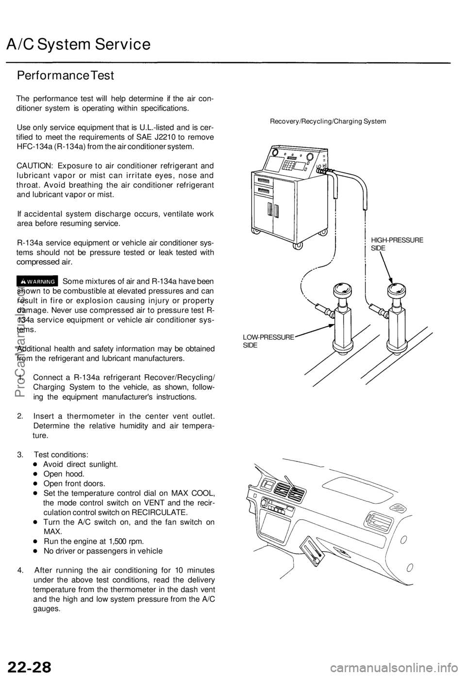
Connect a R-134a refrigerant Recover/Recycling/
Charging System to the vehicle, as shown, follow-
ing the equipment manufacturer's instructions.
Insert a thermometer in the center vent outlet.
Determine the relative humidity and air tempera-
ture.
Recovery/Recycling/Charging System
HIGH-PRESSURE
SIDE
LOW-PRESSURE
SIDE
3. Test conditions:
Avoid direct sunlight.
Open hood.
Open front doors.
Set the temperature control dial on MAX COOL,
the mode control switch on VENT and the recir-
culation control switch on RECIRCULATE.
Turn the A/C switch on, and the fan switch on
MAX.
Run the engine at 1,500 rpm.
No driver or passengers in vehicle
4. After running the air conditioning for 10 minutes
under the above test conditions, read the delivery
temperature from the thermometer in the dash vent
and the high and low system pressure from the A/C
gauges.ProCarManuals.com
Page 614 of 1771
Daytime Runnin g Light s Contro l Uni t Inpu t Tes t (Canada )
Trml Wir e Tes t conditio n Test : Desire d resul t Possibl e caus e if resul t i s no t obtaine d
ProCarManuals.com
Page 615 of 1771
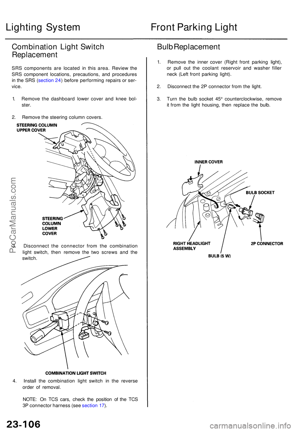
4. Instal l th e combinatio n ligh t switc h i n th e revers e
orde r o f removal .
NOTE : O n TC S cars , chec k th e positio n o f th e TC S
3 P connecto r harnes s (se e sectio n 17 ).
Lightin g Syste m
Combinatio n Ligh t Switc h
Replacemen t
SRS component s ar e locate d i n thi s area . Revie w th e
SR S componen t locations , precautions , an d procedure s
i n th e SR S (sectio n 24 ) befor e performin g repair s o r ser -
vice .
1 . Remov e th e dashboar d lowe r cove r an d kne e bol -
ster .
2 . Remov e th e steerin g colum n covers .
3 . Disconnec t th e connecto r fro m th e combinatio n
ligh t switch , the n remov e th e tw o screw s an d th e
switch .
Front Parkin g Ligh t
Bulb Replacemen t
1. Remov e th e inne r cove r (Righ t fron t parkin g light) ,
o r pul l ou t th e coolan t reservoi r an d washe r fille r
nec k (Lef t fron t parkin g light) .
2 . Disconnec t th e 2 P connecto r fro m th e light .
3 . Tur n th e bul b socke t 45 ° counterclockwise , remov e
i t fro m th e ligh t housing , the n replac e th e bulb .
ProCarManuals.com
Page 618 of 1771
Back-up Light s
Test
NOTE : Befor e testing , chec k th e No . 1 (1 0 A ) fus e i n th e
under-das h fuse/rela y box .
1. Chec k whethe r th e back-u p light s g o o n b y turnin g
the ignitio n switc h O N (II ) an d shiftin g th e shif t leve r
• I f th e back-u p light s d o no t g o on , chec k for :
blow n bulb .
faulty A/ T revers e relay ,
poo r groun d (G301 , G502) .
an ope n in th e wire .
• I f th e back-u p light s g o on , g o t o ste p 2 .
2. Wit h th e shif t leve r i n tur n th e ignitio n
switch OFF .
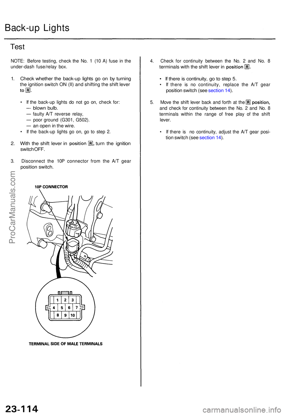
3. Disconnec t th e 10 P connecto r fro m th e A/ T gea r
positio n switch .
4. Chec k fo r continuit y betwee n th e No . 2 an d No . 8
terminal s wit h th e shif t leve r i n
• I f ther e is continuity , g o to ste p 5.
• I f ther e i s n o continuity , replac e th e A/ T gea r
positio n switc h (se e sectio n 14 ).
5 . Mov e th e shif t leve r bac k an d fort h a t th e
an d chec k fo r continuit y betwee n th e No . 2 an d No . 8
terminal s withi n th e rang e o f fre e pla y o f th e shif t
lever .
• I f ther e i s n o continuity , adjus t th e A/ T gea r posi -
tion switc h (se e sectio n 14 ).
ProCarManuals.com
Page 635 of 1771
3. I f necessary , replac e th e A/ T gea r positio n switch .
Cruise Contro l
A/T Gea r Positio n Switc h Tes t
1. Disconnec t th e 10 P connecto r fro m th e A/ T gea r posi -
tion switch .
2. Chec k fo r continuit y betwee n th e terminal s i n eac h
positio n accordin g t o th e tabl e an d confir m tha t
there i s continuit y onl y i n position s
Actuator Solenoi d Tes t
1. Disconnec t th e 4 P connecto r fro m th e actuator .
2 . Chec k fo r resistanc e betwee n th e terminal s accord -
in g t o th e table .
NOTE : Resistanc e wil l var y slightl y wit h tempera -
ture ; specifie d resistanc e is a t 70° F (20°C) .
ProCarManuals.com
Page 655 of 1771
Erasing th e DT C Memor y
To eras e th e DTC(s ) fro m th e SR S unit , us e a Hond a
PG M Teste r (se e th e Hond a PG M Teste r SR S vehicl e
Syste m Supplement ) o r th e followin g procedure .
1 . Mak e sur e th e ignitio n switc h i s OFF .
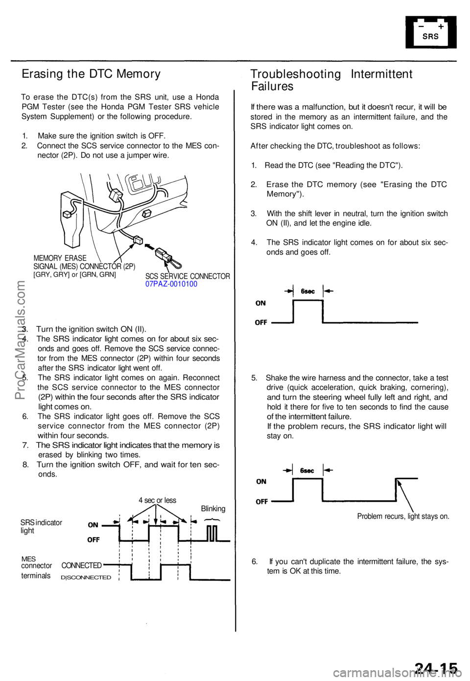
2 . Connec t th e SC S servic e connecto r t o th e ME S con -
necto r (2P) . D o no t us e a jumpe r wire .
MEMOR Y ERAS ESIGNAL (MES ) CONNECTO R (2P )[GRY , GRY ] or [GRN , GRN ]SCS SERVIC E CONNECTO R07PAZ-001010 0
3. Tur n th e ignitio n switc h O N (II) .
4. Th e SR S indicato r ligh t come s o n fo r abou t si x sec -
onds an d goe s off . Remov e th e SC S servic e connec -
to r fro m th e ME S connecto r (2P ) withi n fou r second s
afte r th e SR S indicato r ligh t wen t off .
5 . Th e SR S indicato r ligh t come s o n again . Reconnec t
th e SC S servic e connecto r t o th e ME S connecto r
(2P) withi n th e fou r second s afte r th e SR S indicato r
light come s on .
6. Th e SR S indicato r ligh t goe s off . Remov e th e SC S
servic e connecto r fro m th e ME S connecto r (2P )
within fou r seconds .
7. Th e SR S indicato r ligh t indicate s tha t th e memor y is
erase d b y blinkin g tw o times .
8. Tur n th e ignitio n switc h OFF , an d wai t fo r te n sec -
onds .
4 se c o r les sBlinkin g
SRS indicato rlight
MESconnecto r CONNECTE D
terminals D|SCONNECTE D
Troubleshooting Intermitten t
Failures
If ther e wa s a malfunction , bu t i t doesn' t recur , i t wil l b e
store d i n th e memor y a s a n intermitten t failure , an d th e
SR S indicato r ligh t come s on .
Afte r checkin g th e DTC , troubleshoo t a s follows :
1 . Rea d th e DT C (se e "Readin g th e DTC") .
2. Eras e th e DT C memor y (se e "Erasin g th e DT C
Memory") .
3. Wit h th e shif t leve r i n neutral , tur n th e ignitio n switc h
O N (II) , an d le t th e engin e idle .
4 . Th e SR S indicato r ligh t come s o n fo r abou t si x sec -
ond s an d goe s off .
5 . Shak e th e wir e harnes s an d th e connector , tak e a tes t
driv e (quic k acceleration , quic k braking , cornering) ,
and tur n th e steerin g whee l full y lef t an d right , an d
hold i t ther e fo r fiv e t o te n second s t o fin d th e caus e
of th e intermitten t failure .
If th e proble m recurs , th e SR S indicato r ligh t wil l
stay on .
Proble m recurs , ligh t stay s on .
6. I f yo u can' t duplicat e th e intermitten t failure , th e sys -
te m is O K a t thi s time .
ProCarManuals.com
Page 656 of 1771
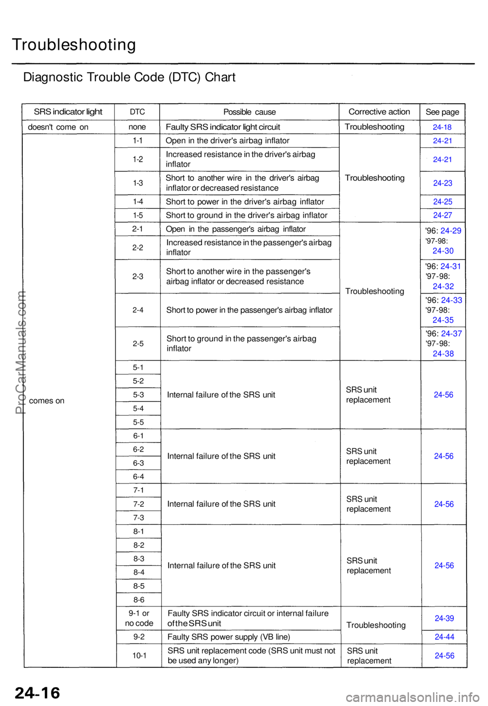
Troubleshooting
Diagnostic Troubl e Cod e (DTC ) Char t
SRS indicato r light
doesn' t com e o n
come s o n
DT C
non e
1-1
1- 2
1-3
1- 4
1-5
2- 1
2- 2
2-3
2- 4
2-5
5-1
5-2
5-3
5- 4
5-5
6-1
6- 2
6-3
6- 4
7- 1
7-2
7-3
8-1
8- 2
8-3
8- 4
8-5
8- 6
9- 1 o r
no cod e
9-2
10- 1
Possibl e caus e
Faulty SR S indicato r ligh t circui t
Open in th e driver' s airba g inflato r
Increase d resistanc e in th e driver' s airba g
inflato r
Shor t t o anothe r wir e i n th e driver' s airba g
inflato r o r decrease d resistanc e
Shor t t o powe r i n th e driver' s airba g inflato r
Shor t t o ground in th e driver' s airba g inflato r
Ope n i n th e passenger' s airba g inflato r
Increase d resistanc e in th e passenger' s airba g
inflato r
Shor t t o anothe r wir e in th e passenger' s
airba g inflato r o r decrease d resistanc e
Shor t t o powe r i n th e passenger' s airba g inflato r
Shor t t o groun d in th e passenger' s airba g
inflato r
Interna l failur e o f th e SR S uni t
Interna l failur e o f th e SR S uni t
Interna l failur e o f th e SR S uni t
Interna l failur e o f th e SR S uni t
Fault y SR S indicato r circui t o r interna l failur e
of th e SR S uni t
Fault y SR S powe r suppl y (V B line )
SR S uni t replacemen t cod e (SR S uni t mus t no t
b e use d an y longer )
Correctiv e actio n
Troubleshootin g
Troubleshootin g
Troubleshootin g
SRS uni t
replacemen t
SRS uni t
replacemen t
SRS uni t
replacemen t
SRS unit
replacemen t
Troubleshootin g
SRS uni t
replacemen t
See pag e
24-1 8
24-2 1
24-21
24-2 3
24-2 5
24-27
'96: 24-2 9
'97-98:
24-3 0
'96: 24-3 1
'97 - 98 :
24-3 2
'96: 24-3 3
'97 - 98 :
24-3 5
'96: 24-3 7
'97 - 98 :
24-3 8
24-56
24-5 6
24-56
24-5 6
24-39
24-4 4
24-5 6
ProCarManuals.com