1995 ACURA TL light
[x] Cancel search: lightPage 988 of 1771
8.
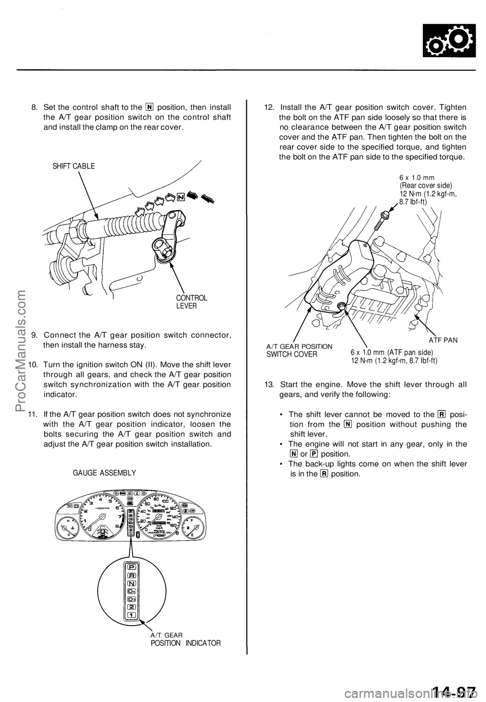
Set the control shaft to the position, then install
the A/T gear position switch on the control shaft
and install the clamp on the rear cover.
SHIFT CABLE
CONTROL
LEVER
9. Connect the A/T gear position switch connector,
then install the harness stay.
10. Turn the ignition switch ON (II). Move the shift lever
through all gears, and check the A/T gear position
switch synchronization with the A/T gear position
indicator.
11. If the A/T gear position switch does not synchronize
with the A/T gear position indicator, loosen the
bolts securing the A/T gear position switch and
adjust the A/T gear position switch installation.
GAUGE ASSEMBLY
A/T GEAR
POSITION INDICATOR
12. Install the A/T gear position switch cover. Tighten
the bolt on the ATF pan side loosely so that there is
no clearance between the A/T gear position switch
cover and the ATF pan. Then tighten the bolt on the
rear cover side to the specified torque, and tighten
the bolt on the ATF pan side to the specified torque.
6 x 1.0 mm
(Rear cover side)
12 N-m (1.2 kgf-m,
8.7 Ibf-ft)
A/T GEAR POSITION
SWITCH COVER
ATF PAN
6 x 1.0 mm (ATF pan side)
12 N-m (1.2 kgf-m, 8.7 Ibf-ft)
13. Start the engine. Move the shift lever through all
gears, and verify the following:
• The shift lever cannot be moved to the posi-
tion from the position without pushing the
shift lever.
• The engine will not start in any gear, only in the
or position.
• The back-up lights come on when the shift lever
is in the position.ProCarManuals.com
Page 1005 of 1771
Lower Valv e Bod y Assembl y
Installatio n
NOTE:
Coat al l part s wit h ATF .
Replac e th e O-ring s an d AT F pa n gasket .
1. Shif t th e transmissio n int o th e position .
2 . Assembl e th e lowe r valv e bod y assembl y (se e pag e
14-11 0 an d 14-111 ).
3 . Instal l th e tw o dowe l pin s o n th e lowe r valv e bod y
assembly .
4 . Pus h th e shif t for k in th e D rang e position .
5 . Instal l th e lowe r valv e bod y puttin g th e manua l
valv e an d th e deten t leve r together , th e revers e
selecto r an d th e shif t for k together , an d joinin g th e
AT F fee d pipe s wit h th e AT F fee d pip e hole s o n th e
transmissio n housing .
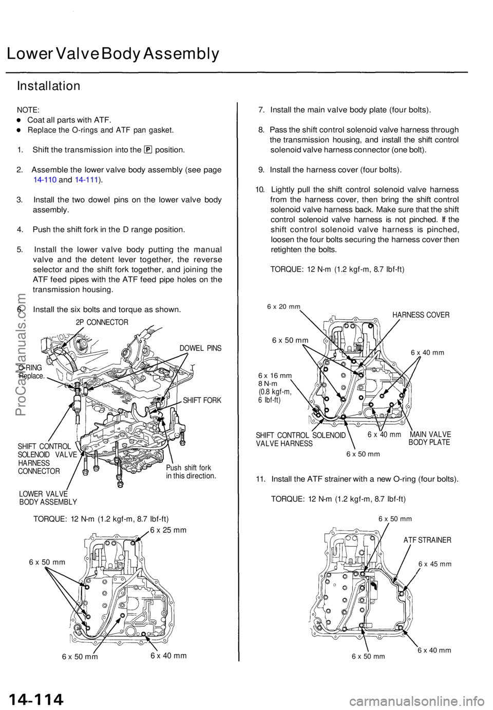
6 . Instal l th e si x bolt s an d torqu e a s shown .
2P CONNECTO R
O-RIN G
Replace . DOWE
L PIN S
SHIF T FOR K
SHIF T CONTRO L
SOLENOI D VALV E
HARNES S
CONNECTO R Pus
h shif t for k
in thi s direction .
LOWER VALV E
BOD Y ASSEMBL Y
TORQUE: 1 2 N- m (1. 2 kgf-m , 8. 7 Ibf-ft )
6 x 25 m m
6 x 5 0 m m
6 x 50 m m 6 x 40 m m
7. Instal l th e mai n valv e bod y plat e (fou r bolts) .
8 . Pas s th e shif t contro l solenoi d valv e harnes s throug h
th e transmissio n housing , an d instal l th e shif t contro l
solenoi d valv e harnes s connecto r (on e bolt) .
9 . Instal l th e harnes s cove r (fou r bolts) .
10 . Lightl y pul l th e shif t contro l solenoi d valv e harnes s
fro m th e harnes s cover , the n brin g th e shif t contro l
solenoi d valv e harnes s back . Mak e sur e tha t th e shif t
contro l solenoi d valv e harnes s i s no t pinched . I f th e
shif t contro l solenoi d valv e harnes s i s pinched ,
loose n th e fou r bolt s securin g th e harnes s cove r the n
retighte n th e bolts .
TORQUE : 1 2 N- m (1. 2 kgf-m , 8. 7 Ibf-ft )
6 x 20 m m
6 x 50 mm
6 x 1 6 m m8 N- m(0.8 kgf-m ,6 Ibf-ft )
SHIFT CONTRO L SOLENOI D
VALV E HARNES S HARNES
S COVE R
6 x 40 m m
6 x 40 m m MAI N VALV E
BOD Y PLAT E
6 x 50 m m
11. Instal l th e AT F straine r wit h a ne w O-rin g (fou r bolts) .
TORQUE : 1 2 N- m (1. 2 kgf-m , 8. 7 Ibf-ft )
6 x 50 m m
AT F STRAINE R
6 x 4 5 m m
6 x 50 m m6 x 40 m m
ProCarManuals.com
Page 1027 of 1771
Valve Body
Repair
NOTE: This repair is only necessary if one or more of
the valves in a valve body do not slide smoothly in their
bores. You may use this procedure to free the valves in
the valve bodies.
1. Soak a sheet of #600 abrasive paper in ATF for
about 30 minutes.
2. Carefully tap the valve body so the sticking valve
drops out of its bore.
CAUTION: It may be necessary to use a small screw-
driver to pry the valve free. Be careful not to scratch
the bore with the screwdriver.
3. Inspect the valve for any scuff marks. Use the ATF-
soaked #600 paper to polish off any burrs that are
on the valve, then wash the valve in solvent and dry
it with compressed air.
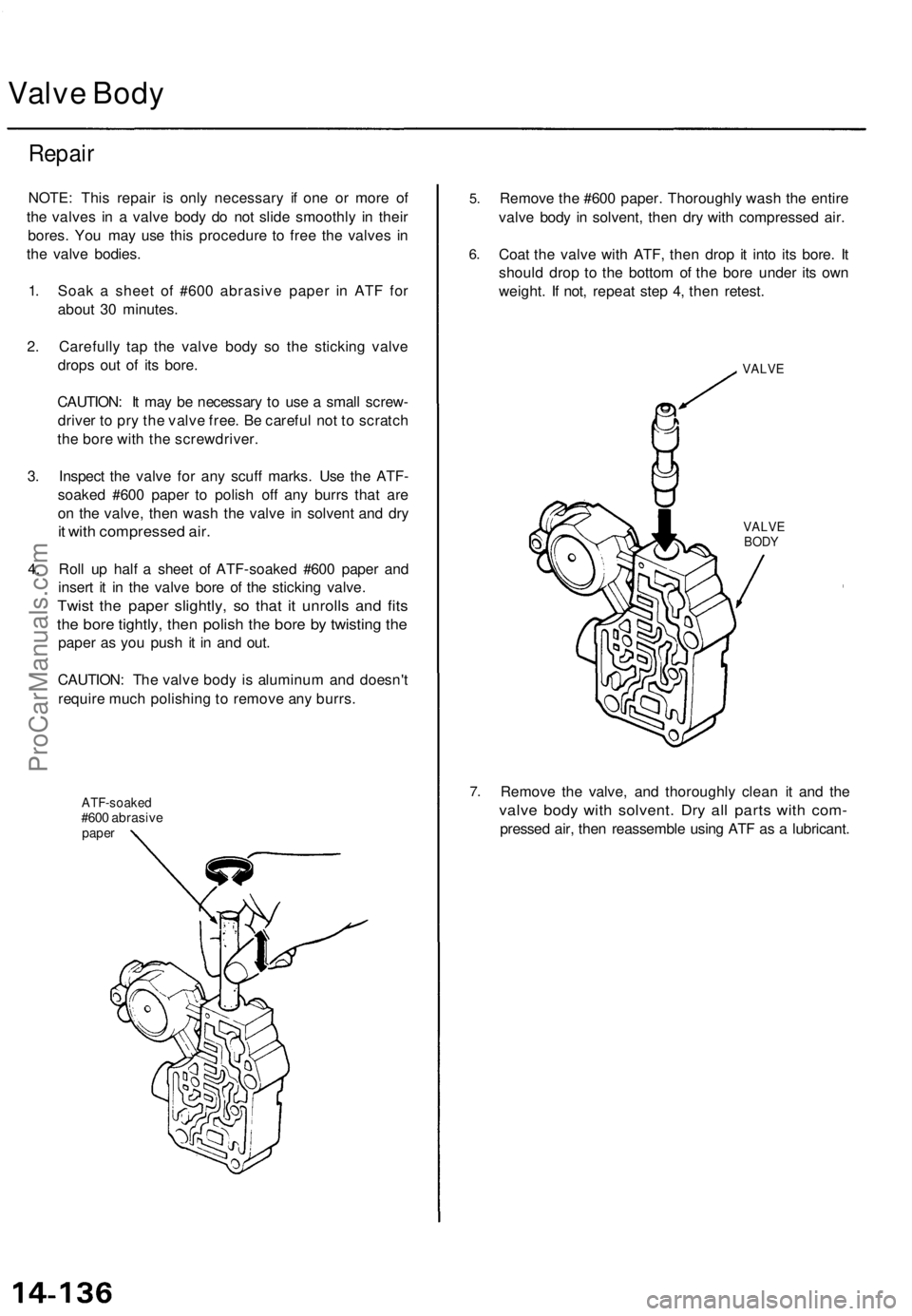
4. Roll up half a sheet of ATF-soaked #600 paper and
insert it in the valve bore of the sticking valve.
Twist the paper slightly, so that it unrolls and fits
the bore tightly, then polish the bore by twisting the
paper as you push it in and out.
CAUTION: The valve body is aluminum and doesn't
require much polishing to remove any burrs.
ATF-soaked
#600 abrasive
paper
5.
6.
Remove the #600 paper. Thoroughly wash the entire
valve body in solvent, then dry with compressed air.
Coat the valve with ATF, then drop it into its bore. It
should drop to the bottom of the bore under its own
weight. If not, repeat step 4, then retest.
VALVE
VALVE
BODY
7.
Remove the valve, and thoroughly clean it and the
valve body with solvent. Dry all parts with com-
pressed air, then reassemble using ATF as a lubricant.ProCarManuals.com
Page 1066 of 1771
Reverse Idler Gear
Parking Brake Pawl
Installation
1. Coat the reverse idler gear shaft, needle bearing
and new O-rings with lithium grease lightly.
2. Assemble new O-rings and needle bearing on the
reverse idler gear shaft.
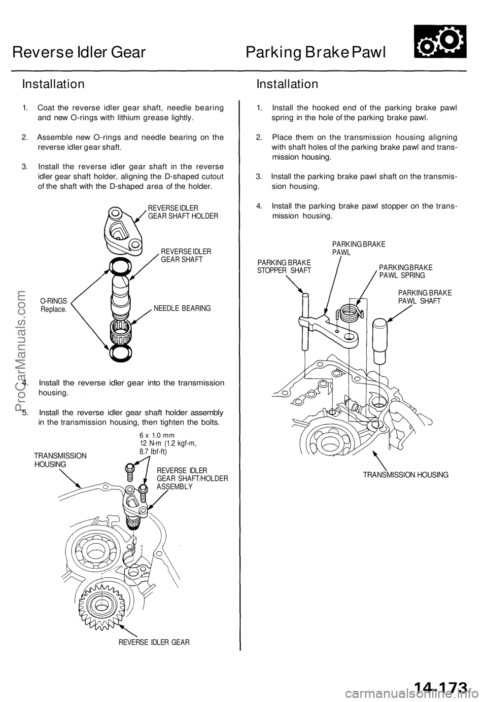
3. Install the reverse idler gear shaft in the reverse
idler gear shaft holder, aligning the D-shaped cutout
of the shaft with the D-shaped area of the holder.
REVERSE IDLER
GEAR SHAFT HOLDER
REVERSE IDLER
GEAR SHAFT
O-RINGS
Replace.
NEEDLE BEARING
4. Install the reverse idler gear into the transmission
housing.
5. Install the reverse idler gear shaft holder assembly
in the transmission housing, then tighten the bolts.
TRANSMISSION
HOUSING
6 x 1.0 mm
12 N-m (1.2 kgf-m,
8.7 Ibf-ft)
REVERSE IDLER
GEAR SHAFT/HOLDER
ASSEMBLY
REVERSE IDLER GEAR
Installation
1. Install the hooked end of the parking brake pawl
spring in the hole of the parking brake pawl.
2. Place them on the transmission housing aligning
with shaft holes of the parking brake pawl and trans-
mission housing.
3. Install the parking brake pawl shaft on the transmis-
sion housing.
4. Install the parking brake pawl stopper on the trans-
mission housing.
PARKING BRAKE
PAWL
PARKING BRAKE
STOPPER SHAFT
PARKING BRAKE
PAWL SPRING
PARKING BRAKE
PAWL SHAFT
TRANSMISSION HOUSINGProCarManuals.com
Page 1076 of 1771
Transmission
Reassembly (cont'd )
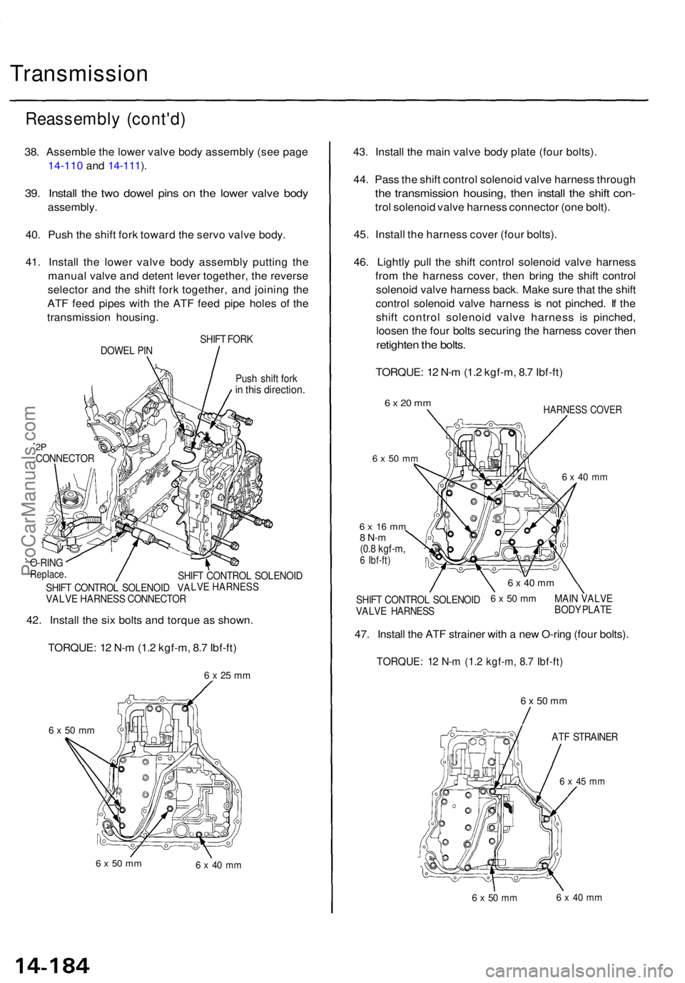
38. Assembl e th e lowe r valv e bod y assembl y (se e pag e
14-110 and 14-111 ).
39 . Instal l th e tw o dowe l pin s o n th e lowe r valv e bod y
assembly .
40. Pus h th e shif t for k towar d th e serv o valv e body .
41 . Instal l th e lowe r valv e bod y assembl y puttin g th e
manua l valv e an d deten t leve r together , th e revers e
selecto r an d th e shif t for k together , an d joinin g th e
AT F fee d pipe s wit h th e AT F fee d pip e hole s o f th e
transmissio n housing .
SHIFT FOR K
DOWE L PI N
Push shif t for k
in thi s direction .
2PCONNECTO R
6 x 50 m m
6 x 50 m m6 x 4 0 m m
43. Instal l th e mai n valv e bod y plat e (fou r bolts) .
44 . Pas s th e shif t contro l solenoi d valv e harnes s throug h
the transmissio n housing , the n instal l th e shif t con -
trol solenoi d valv e harnes s connecto r (on e bolt) .
45 . Instal l th e harnes s cove r (fou r bolts).
46 . Lightl y pul l th e shif t contro l solenoi d valv e harnes s
fro m th e harnes s cover , the n brin g th e shif t contro l
solenoi d valv e harnes s back . Mak e sur e tha t th e shif t
contro l solenoi d valv e harnes s i s no t pinched . I f th e
shif t contro l solenoi d valv e harnes s i s pinched ,
loose n th e fou r bolt s securin g th e harnes s cove r the n
retighte n th e bolts .
TORQUE : 1 2 N- m (1. 2 kgf-m , 8. 7 Ibf-ft )
6 x 20 m m
6 x 5 0 m m
HARNES S COVE R
6 x 4 0 m m
6 x 5 0 m m
6 x 4 5 m m
6 x 50 m m6 x 4 0 m m
42. Instal l th e si x bolt s an d torqu e a s shown .
TORQUE : 1 2 N- m (1. 2 kgf-m , 8. 7 Ibf-ft )
6 x 25 m m
SHIF T CONTRO L SOLENOI D
LVE HARNESS
SHIF T CONTRO L SOLENOI D VA
VALV E HARNES S CONNECTO R
O-RIN
GReplac e
6 x 1 6 m m8 N- m(0.8 kgf-m ,6 Ibf-ft )
6 x 4 0 m m
6 x 50 m mMAI N VALV E
BOD Y PLAT E
SHIF
T CONTRO L SOLENOI D
VALV E HARNES S
47. Instal l th e AT F straine r wit h a ne w O-rin g (fou r bolts) .
TORQUE : 1 2 N- m (1. 2 kgf-m , 8. 7 Ibf-ft )
ATF STRAINE R
ProCarManuals.com
Page 1090 of 1771
Shift Leve r
Link Adjustmen t
Make sur e lifts , jack s an d safet y stand s ar e place d
properl y (se e sectio n 1 ).
Appl y parkin g brake , an d bloc k rea r wheel s s o vehi -
cl e wil l no t rol l of f stand s an d fal l o n yo u whil e work -
in g unde r it .
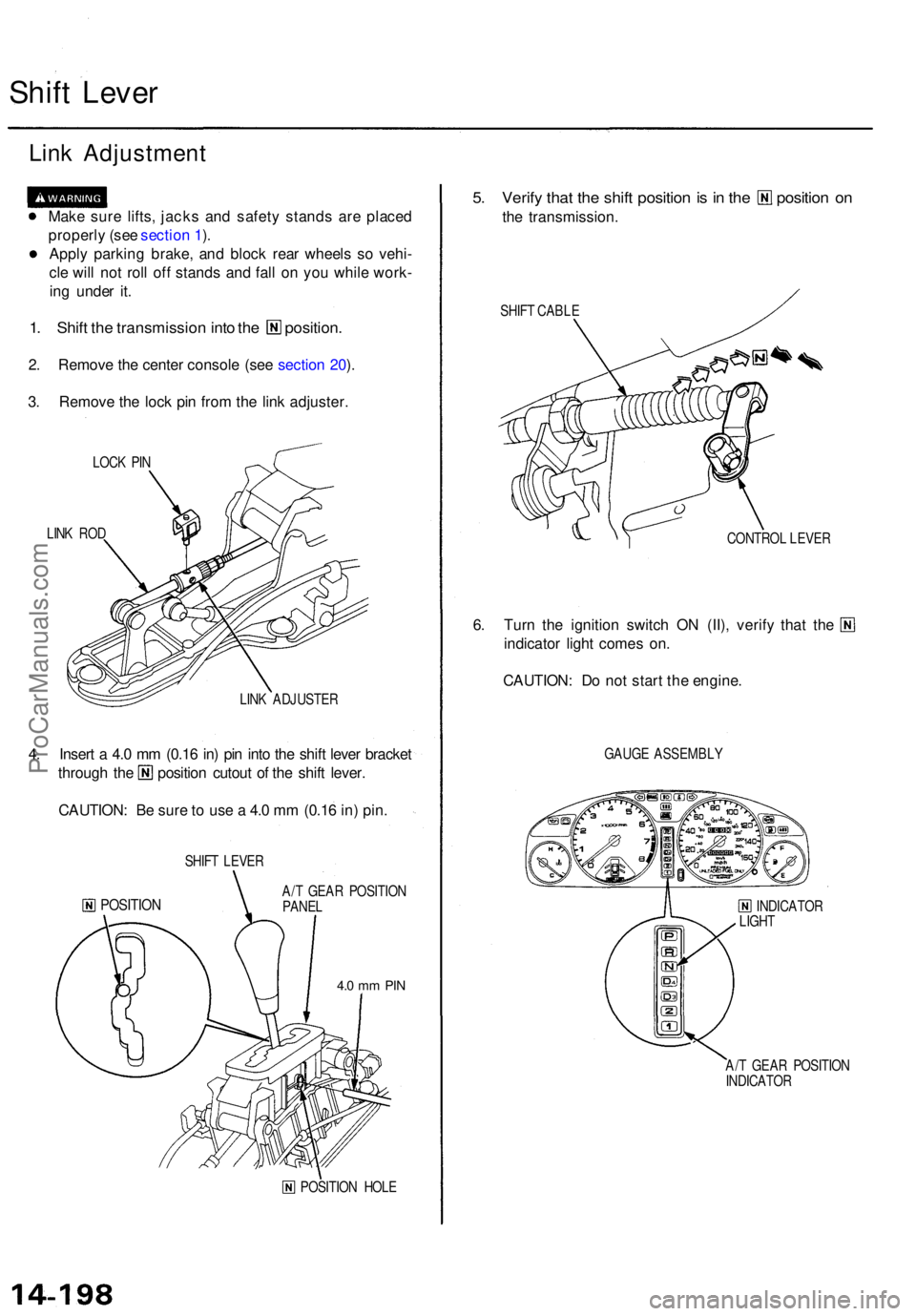
1. Shif t th e transmissio n int o th e position .
2. Remov e th e cente r consol e (se e sectio n 20 ).
3 . Remov e th e loc k pi n fro m th e lin k adjuster .
LOCK PI N
LIN K RO D
LINK ADJUSTE R
4. Inser t a 4. 0 m m (0.1 6 in ) pi n int o th e shif t leve r bracke t
through th e positio n cutou t o f th e shif t lever .
CAUTION : B e sur e to us e a 4. 0 m m (0.1 6 in ) pin .
SHIF T LEVE R
POSITIO NA/T GEA R POSITIO N
PANE L
4.0 m m PI N
POSITIO N HOL E
5. Verif y tha t th e shif t positio n is i n th e positio n o n
the transmission .
SHIFT CABL E
CONTROL LEVE R
6. Tur n th e ignitio n switc h O N (II) , verif y tha t th e
indicator light come s on .
CAUTION : D o no t star t th e engine .
GAUGE ASSEMBL Y
INDICATO R
LIGH T
A/ T GEA R POSITIO N
INDICATO R
ProCarManuals.com
Page 1096 of 1771
Differential Assembl y
Removal
Make sur e jack s an d safet y stand s ar e place d properly ,
and hois t bracket s ar e attache d to correc t position s
o n th e engine .
• Apply parkin g brak e an d bloc k rea r wheel s s o vehicl e
wil l no t rol l of f stand s an d fal l o n yo u whil e workin g
unde r it .
CAUTION : Us e fende r cover s to avoi d damagin g painte d
surfaces .
1. Befor e disconnectin g power , mak e sur e yo u hav e th e
anti-thef t cod e fo r th e radio , the n writ e dow n th e
frequencie s fo r th e radio' s prese t buttons .
2 . Disconnec t th e batter y negativ e (- ) an d positiv e (+ )
cable s fro m th e battery .
3. Remov e th e ai r cleane r housin g assembly .
4 . Remov e th e drai n plug , an d drai n th e differentia l oi l
(se e pag e 1 5-4 ).
5 . Remov e th e driveshaft s an d intermediat e shaf t (se e
sectio n 16 ).
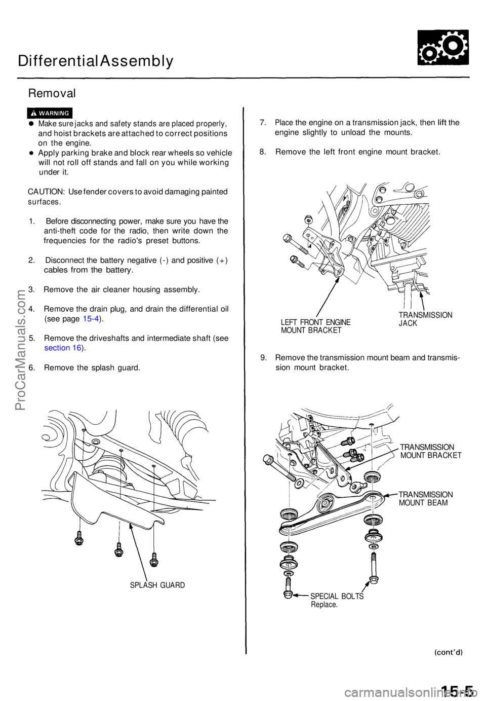
6 . Remov e th e splas h guard .
SPLAS H GUAR D
7. Plac e the engin e on a transmissio n jack , the n lift th e
engin e slightl y t o unloa d th e mounts .
8 . Remov e th e lef t fron t engin e moun t bracket .
LEFT FRON T ENGIN EMOUNT BRACKE T
TRANSMISSIO NJACK
9. Remov e th e transmissio n moun t bea m an d transmis -
sio n moun t bracket .
TRANSMISSIO NMOUNT BRACKE T
TRANSMISSIO NMOUNT BEA M
SPECIA L BOLT SReplace .
ProCarManuals.com
Page 1101 of 1771
Differential Assembl y
Inspection (cont'd )
Bearing preloa d
6 . Remov e th e differentia l cas e cove r an d th e differen -
tia l carrier .
7 . Us e a dial-typ e torqu e wrenc h o n th e driv e pinio n t o
measur e th e driv e pinio n bearin g preload .
Standard: 0.64-1.03 N-m
(6.5-10.5 kgf-cm, 5.6-9.1 Ibf-in)
8. Reinstal l th e differentia l carrie r an d th e differentia l
cas e cover , the n measur e th e tota l bearin g preload .
Standard: Tp* + 0.89-1.13 N-m
(9.1-11.5 kgf-cm, 7.90-9.98 Ibf-in)
*: Driv e pinio n bearin g preloa d i n ste p 7 .
Gea r toot h contac t
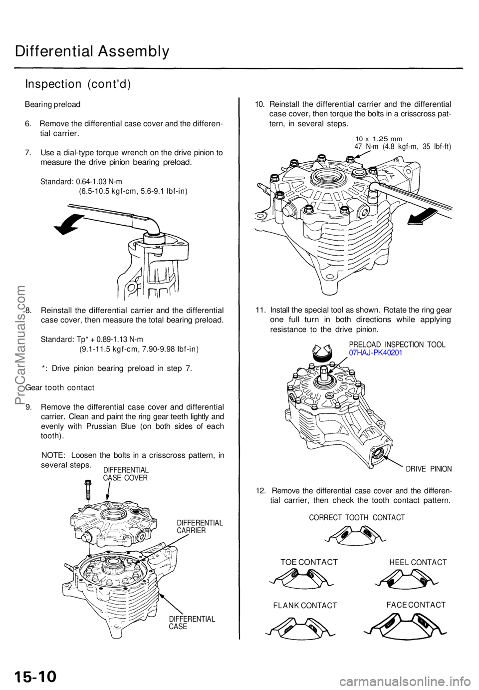
9 . Remov e th e differentia l cas e cove r an d differentia l
carrier . Clea n an d pain t th e rin g gea r teet h lightl y an d
evenl y with Prussia n Blu e (o n bot h side s o f eac h
tooth) .
NOTE : Loose n th e bolt s i n a crisscros s pattern , i n
severa l steps .
DIFFERENTIA LCARRIER
DIFFERENTIA L
CAS E
10. Reinstal l th e differentia l carrie r an d th e differentia l
cas e cover , the n torqu e th e bolt s in a crisscros s pat -
tern , i n severa l steps .
10 x 1.2 5 mm47 N- m (4. 8 kgf-m , 3 5 Ibf-ft )
11. Instal l th e specia l too l a s shown . Rotat e th e rin g gea r
one ful l tur n i n bot h direction s whil e applyin g
resistanc e t o th e driv e pinion .
PRELOA D INSPECTIO N TOO L07HAJ-PK40201
DRIVE PINIO N
12. Remov e th e differentia l cas e cove r an d th e differen -
tia l carrier , the n chec k th e toot h contac t pattern .
CORREC T TOOT H CONTAC T
TOE CONTAC T HEE L CONTAC T
FLANK CONTAC T FAC E CONTAC T
DIFFERENTIA L
CAS E COVE R
ProCarManuals.com