1995 ACURA TL steering wheel adjustment
[x] Cancel search: steering wheel adjustmentPage 468 of 1771
Rack Guide Adjustment
NOTE: Perform rack guide adjustment with the wheels
in the straight ahead position.
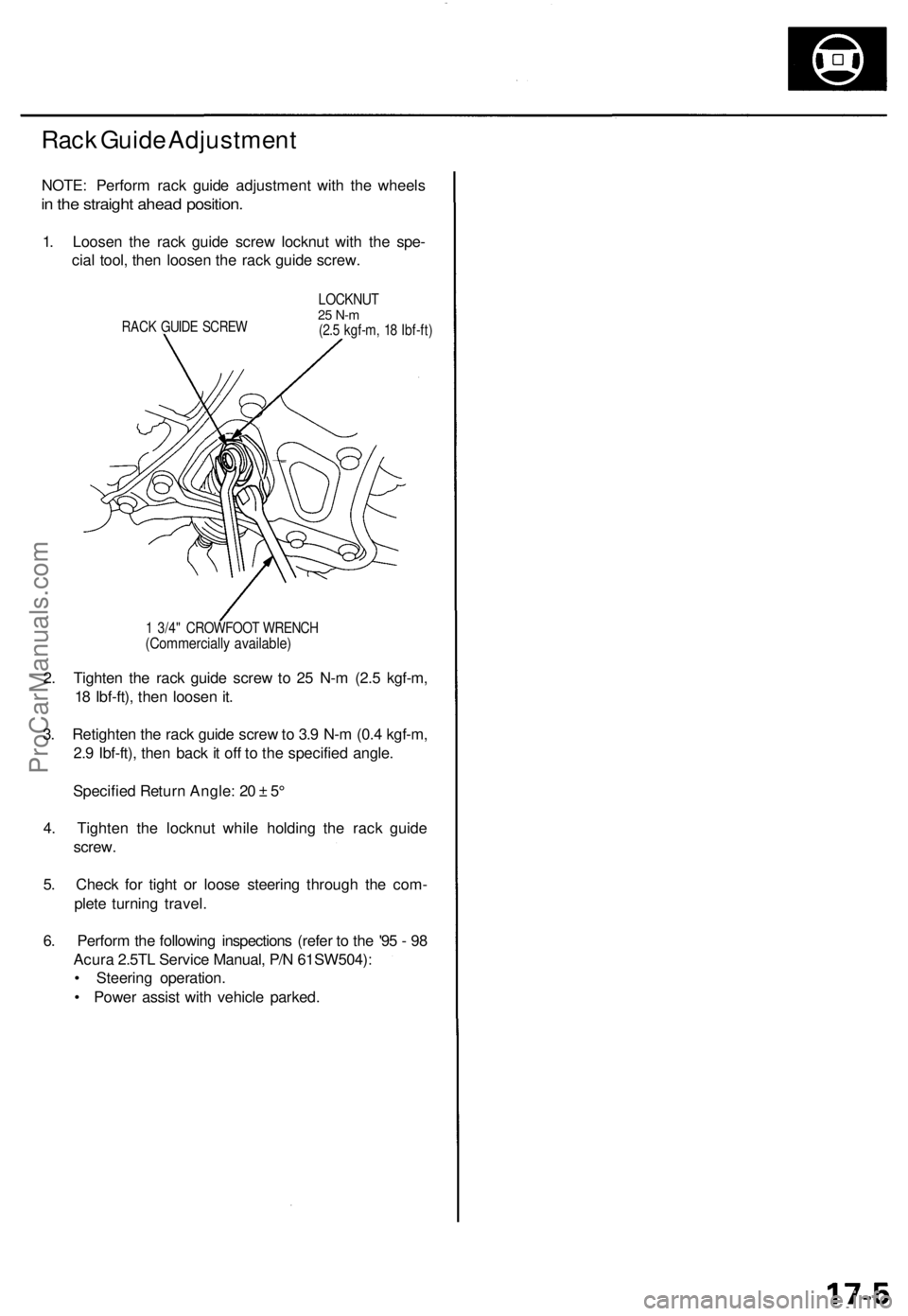
1. Loosen the rack guide screw locknut with the spe-
cial tool, then loosen the rack guide screw.
RACK GUIDE SCREW
LOCKNUT
25 N-m
(2.5 kgf-m, 18 Ibf-ft)
1 3/4" CROWFOOT WRENCH
(Commercially available)
2. Tighten the rack guide screw to 25 N-m (2.5 kgf-m,
18 Ibf-ft), then loosen it.
3. Retighten the rack guide screw to 3.9 N-m (0.4 kgf-m,
2.9 Ibf-ft), then back it off to the specified angle.
Specified Return Angle: 20 ± 5°
4. Tighten the locknut while holding the rack guide
screw.
5. Check for tight or loose steering through the com-
plete turning travel.
6. Perform the following inspections (refer to the '95 - 98
Acura 2.5TL Service Manual, P/N 61SW504):
• Steering operation.
• Power assist with vehicle parked.ProCarManuals.com
Page 666 of 1771
Cable Reel
Replacement (cont'd)
12.
NOTE:
Before installing the steering wheel, the front
wheels should be aligned straight ahead.
Be sure to install the harness wires so that they
are not pinched or interfering with other parts.
After reassembly, confirm that the wheels are
still turned straight ahead and that the steering
wheel spoke angle is correct (road test). If minor
spoke angle adjustment is necessary, do so only
by adjusting the tie-rods, not by removing and
repositioning the steering wheel.
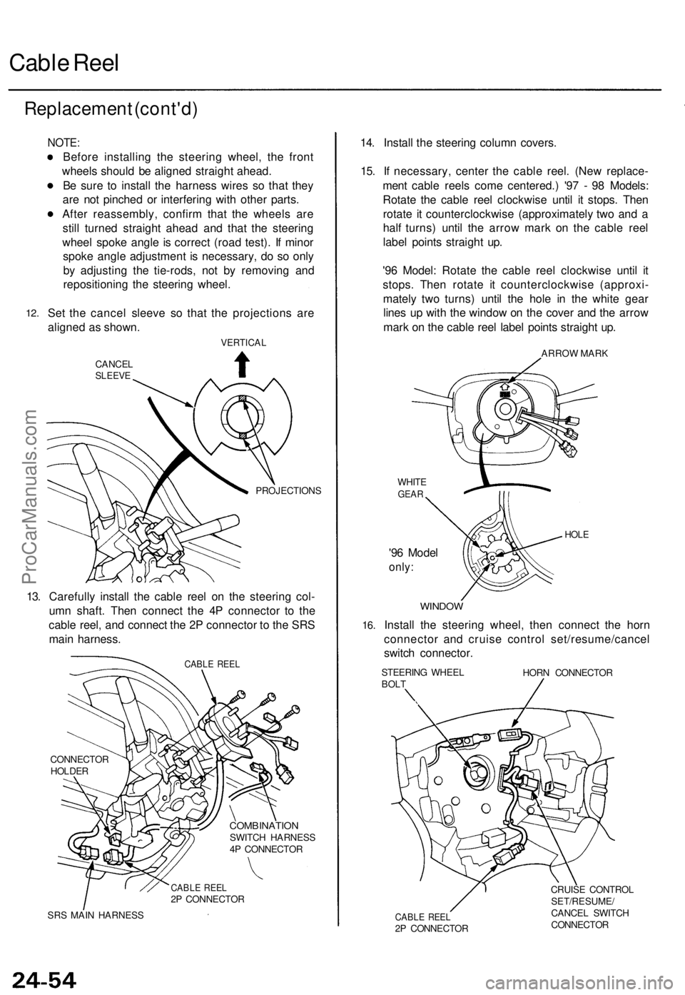
Set the cancel sleeve so that the projections are
aligned as shown.
VERTICAL
CANCEL
SLEEVE
PROJECTIONS
13. Carefully install the cable reel on the steering col-
umn shaft. Then connect the 4P connector to the
cable reel, and connect the 2P connector to the SRS
main harness.
CABLE REEL
CONNECTOR
HOLDER
COMBINATION
SWITCH HARNESS
4P CONNECTOR
CABLE REEL
2P CONNECTOR
SRS MAIN HARNESS
14. Install the steering column covers.
15. If necessary, center the cable reel. (New replace-
ment cable reels come centered.) '97 - 98 Models:
Rotate the cable reel clockwise until it stops. Then
rotate it counterclockwise (approximately two and a
half turns) until the arrow mark on the cable reel
label points straight up.
'96 Model: Rotate the cable reel clockwise until it
stops. Then rotate it counterclockwise (approxi-
mately two turns) until the hole in the white gear
lines up with the window on the cover and the arrow
mark on the cable reel label points straight up.
ARROW MARK
WHITE
GEAR
'96 Model
only:
HOLE
16.
WINDOW
Install the steering wheel, then connect the horn
connector and cruise control set/resume/cancel
switch connector.
STEERING WHEEL
BOLT
HORN CONNECTOR
CABLE REEL
2P CONNECTOR
CRUISE CONTROL
SET/RESUME/
CANCEL SWITCH
CONNECTORProCarManuals.com
Page 1144 of 1771
Component Location s
Index
NOTE :
• I f a n intac t airba g assembl y ha s bee n remove d fro m a scrappe d vehicl e o r ha s bee n foun d defectiv e o r damage d dur -
in g transit , storag e o r service , i t shoul d b e deploye d (se e sectio n 24 ).
• Befor e removin g th e steerin g gearbox , remov e th e driver' s airba g assembl y an d steerin g wheel .
• Afte r installin g th e steerin g gearbox , chec k th e whee l alignmen t an d adjus t i f necessary .
SR S component s ar e locate d in thi s area . Revie w th e SR S componen t locations , precautions , an d procedure s in th e SR S
( sectio n 24 ) befor e performin g repair s o r service .
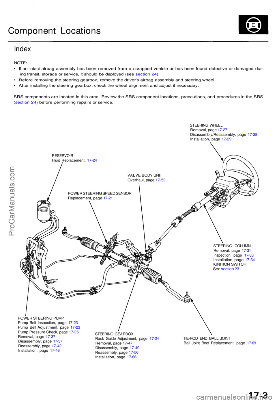
STEERIN G WHEE LRemoval , pag e 17-2 7
Disassembly/Reassembly , pag e 17-2 8
Installation , pag e 17-2 9
RESERVOI RFluid Replacement , 17-2 4
VALVE BOD Y UNI T
Overhaul , pag e 17-5 2
POWE R STEERIN G SPEE D SENSO R
Replacement , pag e 17-2 1
STEERING COLUM N
Removal , pag e 17-3 1
Inspection , pag e 17-3 3
Installation , pag e 17-3 4IGNITIO N SWITC HSee sectio n 2 3
POWE R STEERIN G PUM P
Pum p Bel t Inspection , pag e 17-2 3
Pum p Bel t Adjustment , pag e 17-2 3
Pum p Pressur e Check , pag e 17-2 5
Removal , pag e 17-3 7
Disassembly , pag e 17-3 7
Reassembly , pag e 17-4 2
Installation , pag e 17-4 6
STEERIN G GEARBO XRack Guid e Adjustment , pag e 17-2 4
Removal , pag e 17-4 7
Disassembly , pag e 17-4 9
Reassembly , pag e 17-5 6
Installation , pag e 17-6 6 TIE-RO
D EN D BAL L JOIN T
Bal l Join t Boo t Replacement , pag e 17-6 9
ProCarManuals.com
Page 1162 of 1771
Inspection an d Adjustmen t
Steering Operatio n
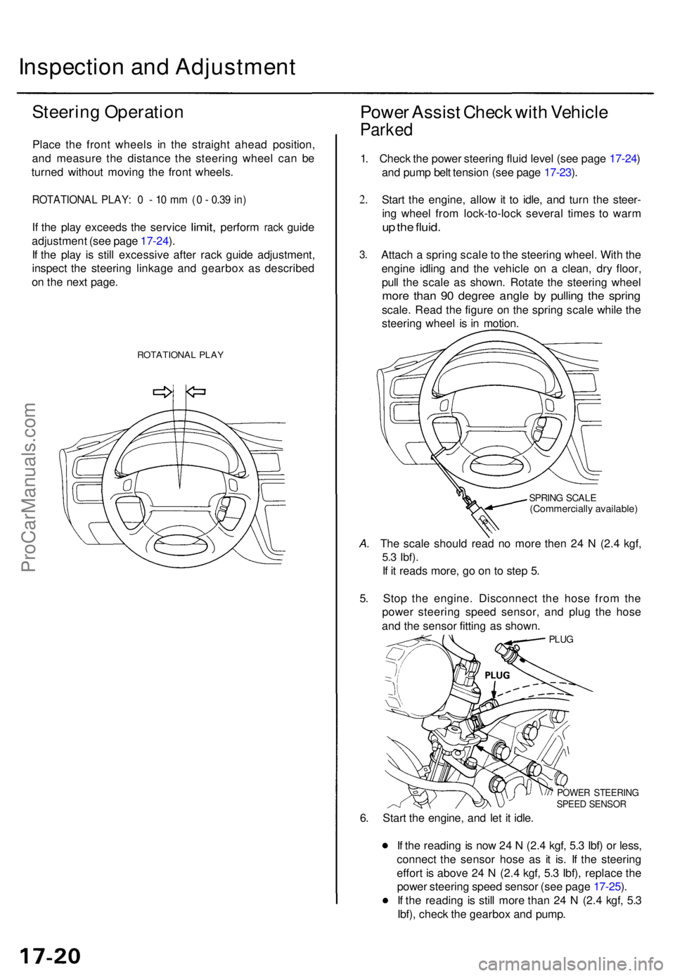
Place th e fron t wheel s i n th e straigh t ahea d position ,
an d measur e th e distanc e th e steerin g whee l ca n b e
turne d withou t movin g th e fron t wheels .
ROTATIONA L PLAY : 0 - 10 m m (0 - 0.3 9 in )
If th e pla y exceed s the servic e limit, perfor m rack guid e
adjustmen t (se e pag e 17-24 ).
I f th e pla y i s stil l excessiv e afte r rac k guid e adjustment ,
inspec t th e steerin g linkag e an d gearbo x a s describe d
o n th e nex t page .
ROTATIONA L PLA Y
Powe r Assis t Chec k wit h Vehicl e
Parked
1. Chec k th e powe r steerin g flui d leve l (se e pag e 17-24 )
an d pum p bel t tensio n (se e pag e 17-23 ).
2 .
3 .
Star t th e engine , allo w it t o idle , an d tur n th e steer -
in g whee l fro m lock-to-loc k severa l time s t o war m
up th e fluid .
Attac h a sprin g scal e to th e steerin g wheel . Wit h th e
engin e idlin g an d th e vehicl e o n a clean , dr y floor ,
pul l th e scal e a s shown . Rotat e th e steerin g whee l
more tha n 9 0 degre e angl e b y pullin g th e sprin g
scale. Rea d th e figur e o n th e sprin g scal e whil e th e
steerin g whee l i s i n motion .
SPRING SCAL E(Commerciall y available )
A. Th e scal e shoul d rea d n o mor e the n 2 4 N (2. 4 kgf ,
5.3 Ibf) .
If i t read s more , g o o n t o ste p 5 .
5 . Sto p th e engine . Disconnec t th e hos e fro m th e
powe r steerin g spee d sensor , an d plu g th e hos e
an d th e senso r fittin g a s shown .
PLUG
POWE R STEERIN GSPEED SENSO R
6. Star t th e engine , an d le t i t idle .
I f th e readin g is no w 2 4 N (2. 4 kgf , 5. 3 Ibf ) o r less ,
connec t th e senso r hos e a s i t is . I f th e steerin g
effor t i s abov e 2 4 N (2. 4 kgf , 5. 3 Ibf) , replac e th e
powe r steerin g spee d senso r (se e pag e 17-25 ).
I f th e readin g i s stil l mor e tha n 2 4 N (2. 4 kgf , 5. 3
Ibf) , chec k th e gearbo x an d pump .
ProCarManuals.com
Page 1172 of 1771
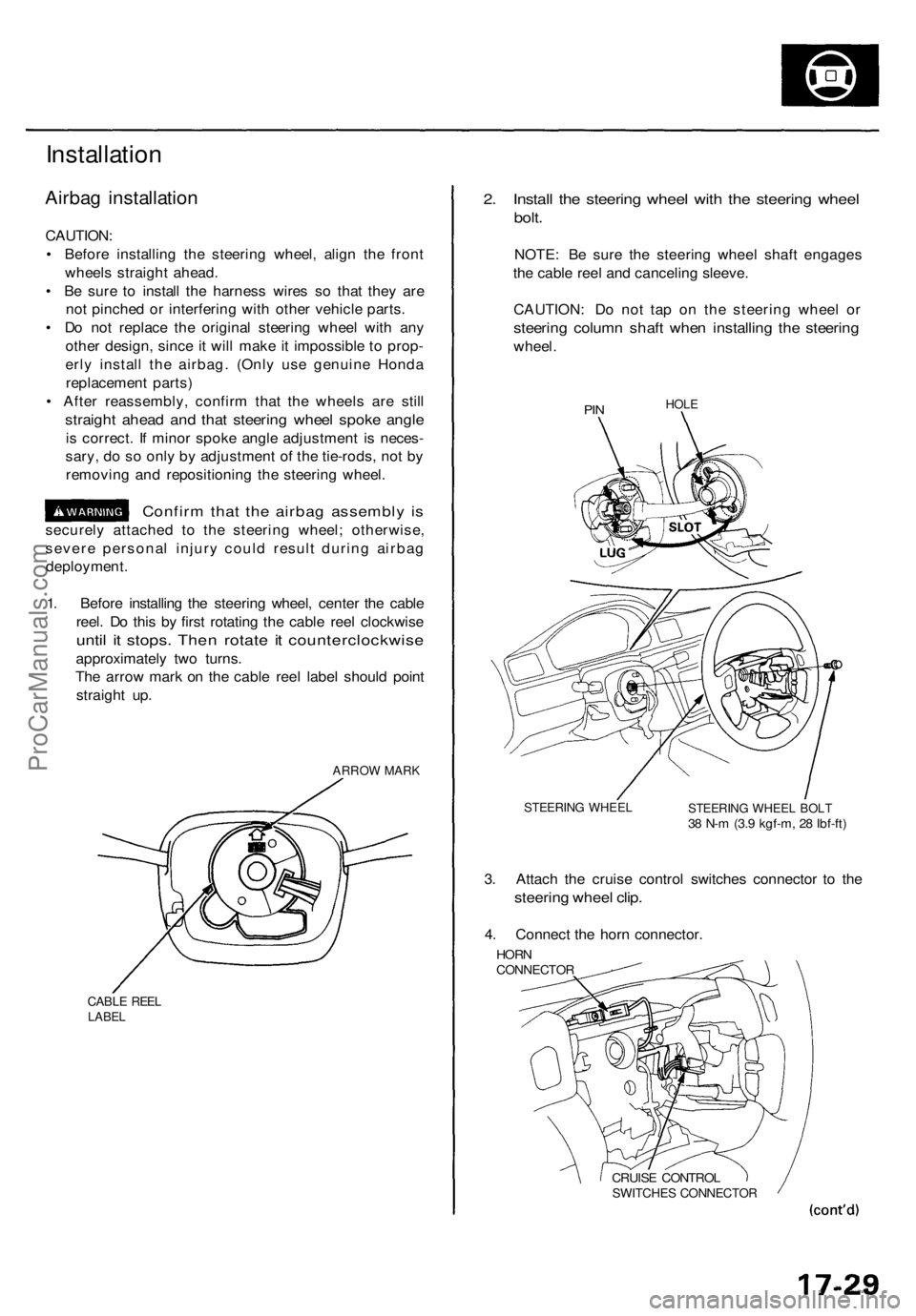
Installation
Airbag installation
CAUTION:
• Before installing the steering wheel, align the front
wheels straight ahead.
• Be sure to install the harness wires so that they are
not pinched or interfering with other vehicle parts.
• Do not replace the original steering wheel with any
other design, since it will make it impossible to prop-
erly install the airbag. (Only use genuine Honda
replacement parts)
• After reassembly, confirm that the wheels are still
straight ahead and that steering wheel spoke angle
is correct. If minor spoke angle adjustment is neces-
sary, do so only by adjustment of the tie-rods, not by
removing and repositioning the steering wheel.
Confirm that the airbag assembly is
securely attached to the steering wheel; otherwise,
severe personal injury could result during airbag
deployment.
1. Before installing the steering wheel, center the cable
reel. Do this by first rotating the cable reel clockwise
until it stops. Then rotate it counterclockwise
approximately two turns.
The arrow mark on the cable reel label should point
straight up.
ARROW MARK
CABLE REEL
LABEL
2. Install the steering wheel with the steering wheel
bolt.
NOTE: Be sure the steering wheel shaft engages
the cable reel and canceling sleeve.
CAUTION: Do not tap on the steering wheel or
steering column shaft when installing the steering
wheel.
PIN
HOLE
STEERING WHEEL
STEERING WHEEL BOLT
38 N-m (3.9 kgf-m, 28 Ibf-ft)
3. Attach the cruise control switches connector to the
steering wheel clip.
4. Connect the horn connector.
HORN
CONNECTOR
CRUISE CONTROL
SWITCHES CONNECTORProCarManuals.com
Page 1746 of 1771
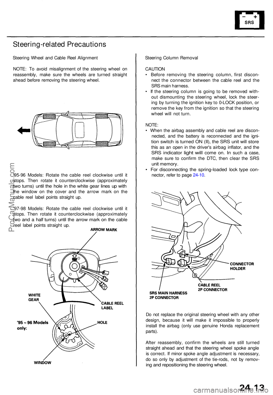
Steering-related Precautions
Steering Whee l an d Cabl e Ree l Alignmen t
NOTE : T o avoi d misalignmen t o f th e steerin g whee l o n
reassembly , mak e sur e th e wheel s ar e turne d straigh t
ahea d befor e removin g th e steerin g wheel .
'95-9 6 Models : Rotat e th e cabl e ree l clockwis e unti l i t
stops . The n rotat e i t counterclockwis e (approximatel y
two turns ) unti l th e hol e in th e whit e gea r line s u p wit h
the windo w o n th e cove r an d th e arro w mar k o n th e
cabl e ree l labe l point s straigh t up .
'97-9 8 Models : Rotat e th e cabl e ree l clockwis e unti l i t
stops . The n rotat e i t counterclockwis e (approximatel y
two an d a hal f turns ) unti l th e arro w mar k o n th e cabl e
reel labe l point s straigh t up . Steerin
g Colum n Remova l
CAUTIO N
• Befor e removin g th e steerin g column , firs t discon -
nec t th e connecto r betwee n th e cabl e ree l an d th e
SR S mai n harness .
• I f th e steerin g colum n i s goin g t o b e remove d with -
ou t dismountin g th e steerin g wheel , loc k th e steer -
in g b y turnin g th e ignitio n ke y to 0-LOC K position , o r
remov e th e ke y fro m th e ignitio n s o tha t th e steerin g
whee l wil l no t turn .
NOTE :
• Whe n th e airba g assembl y an d cabl e ree l ar e discon -
nected , an d th e batter y i s reconnecte d an d th e igni -
tion switc h is turne d O N (II) , th e SR S uni t wil l stor e
this a s a n ope n i n th e driver' s airba g inflator , an d th e
SR S indicato r light will com e on. I n suc h a case ,
mak e sur e t o confir m th e DTC , the n clea r th e SR S
unit memory .
• Fo r disconnectin g th e spring-loade d loc k typ e con -
nector , refe r t o pag e 24-10 .
D o no t replac e th e origina l steerin g whee l wit h an y othe r
design , becaus e i t wil l mak e i t impossibl e t o properly
instal l th e airba g (onl y us e genuin e Hond a replacemen t
parts) .
Afte r reassembly , confir m th e wheel s ar e stil l turne d
straight ahea d an d tha t th e steerin g whee l spok e angl e
is correct . I f mino r spok e angl e adjustment is necessary ,
d o s o onl y b y adjustmen t o f th e tie-rods , no t b y remov -
ing an d repositionin g th e steerin g wheel .
ProCarManuals.com